Zip HydroTap G4 Installation Instructions Manual
Hide thumbs
Also See for HydroTap G4:
- User manual ,
- Installation instructions manual (40 pages) ,
- Installation and operating instructions manual (28 pages)
Table of Contents
Advertisement
Quick Links
Advertisement
Table of Contents

Related Manuals for Zip HydroTap G4


Summary of Contents for Zip HydroTap G4
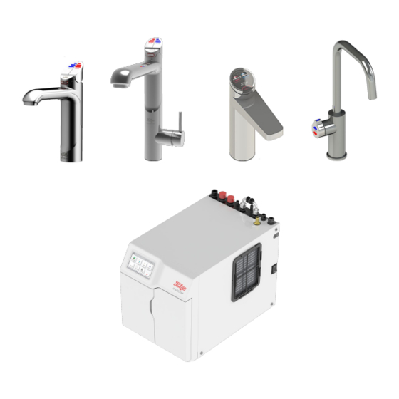
- Page 1 Installation instructions Zip HydroTap G4 ® Filtered boiling and chilled drinking water for commercial kitchens and tea rooms. Affix model number label here 802411UK 802411UK - HT G4 BC(H), AN, AV Commercial compact installation instructions - January 2015 - V1.03...
- Page 2 Notes Page 2 of 32 802411UK - HT G4 BC(H), AN, AV Commercial compact installation instructions - January 2015 - V1.03...
-
Page 3: Table Of Contents
Index HydroTap ® G4 specifications Installation check list ........................4 General product features ......................5 Important safety instructions ......................6 Warnings and regulatory information ................... 7 Major components and accessories ..................... 8 Technical specifications ....................... 9 Before installation and site requirements ..................10 Installation instructions - Measure and cut all the tap holes before fitting the taps. -
Page 4: Installation Checklist
Installation checklist Before installation • Read the instructions and check if there is adequate space to install all of the components. Note not all fittings are supplied with the appliance kit. Isolation valves are not supplied. • • Check the mains water pressure is within min. / max. requirements (see page 9). •... -
Page 5: General Product Features
General product features Thank you for purchasing a Zip HydroTap G4. Please read and follow these instructions carefully to ensure ® safe and trouble free operation. If help and advice is required, please call 0845 6 005 005 or 0345 6 005 005. -
Page 6: Important Safety Instructions
Important safety instructions This manual contains important safety and installation instructions for the Zip HydroTap ® Please read all warnings, installation requirements and installation instructions before installing any Zip HydroTap G4. This system must be installed in accordance with water supply byelaws, ®... -
Page 7: Warnings And Regulatory Information
• All installation and service work must be completed by trained and suitably qualified tradespeople. Faulty operation due to unqualified persons working on this product, or any other Zip product may void warranty coverage. • As the installer, it is your responsibility to supply (if necessary) and install all valves as required by local regulations and relevant standards. -
Page 8: Major Components And Accessories
HE45004 valve and T-piece (supplied with vented mixer taps) *ZT200G4 kit to fit filters 1 x User guide and FL2300 (Light commercial use) ZIP HydroTap ® 1 x Quick start User Guide Tap Operation....(Pages 2-5) • • LCD Screen & Menu ..(Pages 6-18) •... -
Page 9: Technical Specifications
Technical specifications Commercial models BC100(140)/75G4 Boiling, chilled and filtered. BCH100(140)/75G4 4-in-1 Boiling, chilled and filtered and mixed hot & cold. AN100/(140)/75G4 All-in-One - 'Mains'. Boiling, chilled and filtered and mixed hot & cold. AV100/(140)/75G4 All-in-One - 'Vented'. Boiling, chilled and filtered and mixed hot & cold. Disabled lever controls, (order as an option). -
Page 10: Before Installation And Site Requirements
G4 BC,AN, AV and BCH 140/75 models, 2 x 220-240V AC, ® 13A fused spurs will be required. (One spur is for the Zip HydroTap G4 and the other for the booster). ® • Fused spurs should provide all pole disconnection with a contact separation of at least 3mm, installed in accordance with IEE regulations. -
Page 11: Section 1 - Tap Installation
Position the tap such that it dispenses into the sink bowl with ample clearance for a cup or tea pot. Alternatively, the tap could be mounted away from the sink using a Zip Font ZT008 (tap extension included), available as an accessory. BC HydroTap ®... -
Page 12: Hydrotap ® G4 Tap Installation
® HydroTap G4 - tap installation Models BC100/75G4, BC140/75G4, BCH100/75G4 & BCH140/75G4 All thread rod Clearance Envelope Black plastic 470mm spacer Spider clamp Stainless steel spacer Sink / worktop Ø35mm 35mm hole is required in the sink / worktop. Ø Note make sure the tap location will allow the tap spout to drain into the sink. - Page 13 Installation instructions (see page 25,28 for Command-Centre connections) ® HydroTap G4 Installation Black plastic spacer Stainless steel Fit the washer stainless steel washer, Spider clamp spider clamp, and nut. 35mm hole Note feed each of the three tubes and USB cable evenly in between the legs of the spider Pass all the hoses, tubes and USB clamp during installation.
-
Page 14: Mixer Tap Installation
Mixer tap installation Models BCH100/75G4 and BCH140/75G4 Clearance Braided Envelope Upper rubber hose x 3 washer Lower rubber washer Washer 470mm Sink / worktop Upper rubber washer Ø35mm Lower rubber 35mm hole is required in the sink / worktop. washer Ø... -
Page 15: All-In-One Tap 'Mains' Installation
All-in-One tap 'Mains' installation Models AN100/75G4 and AN140/75G4 Clearance O-ring Envelope Base block USB cable spider All thread Base block nut 470mm 161.50 O-ring Sink / work top Ø50mm Ø50mm hole is required in the sink / worktop. Fit the o-ring to the underside of the AIO tap Note make sure the tap location will allow the tap then pass tubes, hoses and cable through spout to drain into the sink. - Page 16 Installation instructions 1.10 Fit the base block spider to the Note Feed each of the tubes and underside of the All- in-One tap. electrical cable evenly in between the legs of the base block spider. Note All silicon tubes must be cut to size. They must have All silicon tubes must be cut to size.
-
Page 17: All-In-One Tap 'Vented' Installation
All-in-One tap 'Vented' installation Models AV100/75G4 and AV140/75G4 1.12 Clearance O-ring Envelope Base block USB cable spider All thread Base block nut 470mm 1.13 161.50 O-ring Sink top Ø50mm Ø50mm hole is required in the sink / worktop. Fit the o-ring to the underside of the AIO tap Note make sure the tap location will allow the tap then pass tubes, hoses and cable through spout to drain into the sink. - Page 18 Installation instructions 1.14 Mount the base Note Feed each block spider to the of the tubes and underside of the electrical cable evenly All-in-One tap. in between the legs of the base block spider. Note All silicon tubes must be cut to size. They must have All silicon tubes must be cut to size.
-
Page 19: Section 2- Ventilation
Section 2 Ventilation Ventilation for all models • The clearance envelope dimensions stated in the specification sheets and installation instructions must be observed. • Adequate ventilation must be provided to ensure that the cupboard space temperature does not exceed Preferred arrangement •... -
Page 20: Booster Specifications And Descriptions
Booster system 3.1 Product description The booster system is a compact electronically controlled auxiliary water heater. It is intended to provide pre-heating of water before it enters the Zip HydroTap G4 boiling tank. The booster is supplied ® as standard with BC140/75G4, BCH140/75G4 AN140/75G4 and AV140/75G4 models. -
Page 21: Section 3 - Booster Installation
Booster installation 3.2 Installation procedure Site requirements • Booster must only be installed in a frost-free area. Never expose the booster to frost. • The booster is designed for wall mounted installation and must be installed with water connectors facing upwards. •... -
Page 22: Braided Hose Connections
Note 1 This appliance is intended for use with the Zip HydroTap G4 Command-Centre ® Note 2 Water connections must be pointing vertically upwards. Note 3 The booster unit should be installed as close as possible to the Zip HydroTap G4 as the 500mm ® connection hoses cannot be lengthened. -
Page 23: 3.6 Filter / Softener Installation
Filter / softener installation An external filter / softener may be fitted to reduce the incidence of scale build up in the hot tank or may be supplied at the customer’s request. (Scale filter head fitting kit order code ZT200G4 or ZT300G4). 3.5 Mounting the filter head •... -
Page 24: Section 4 - Command-Centre
Section 4 Command-Centre installation 4.1 External bypass valve The diverter bypass valve allows the user to choose to have the boiling feed water bypass the internal filter and only be filtered by the external filtration. This diverter valve is located at the rear panel of the Command-Centre , see the diagram below. -
Page 25: Model Bc100/75G4
Installation instructions (for BC140/75G4 also connect a booster, see section 3 page 20) 4.3 Model BC100/75G4 Note All silicon All silicon Note tubes / plastic pipes tubes / plastic pipes must be cut to size. must be cut to size. They must have a They must have a constant fall back to... -
Page 26: Model An100/75G4 Aio 'Mains
Installation instructions (for AN140/75G4 also connect a booster, see section 4.4 Model AN100/75G4 All-in-One 'Mains' 3 page 20) Note All silicon All silicon Note tubes / plastic pipes tubes / plastic pipes must be cut to size. must be cut to size. They must have a They must have a constant fall back to... -
Page 27: Model Av140/75G4 Aio 'Vented
Installation instructions (for AV100/75G4 option, do not connect the 4.5 Model AV140/75G4 All-in-One 'Vented' booster) Booster HT Mixer Note All silicon All silicon connections Note tubes / plastic pipes tubes / plastic pipes must be cut to size. must be cut to size. They must have a They must have a constant fall back to... -
Page 28: Model Bch140/75G4 4-In-1 'Vented
Installation instructions (for BCH100/75G4 option,do not connect the booster) 4.6 Model BCH140/75G4 4-in-1 'Vented' Booster HT Mixer connections Note All silicon All silicon Note tubes / plastic pipes tubes / plastic pipes must be cut to size. must be cut to size. They must have a They must have a constant fall back to... -
Page 29: Section 5 - Commissioning
Section 5 Commissioning The HydroTap G4 is now ready to be commissioned. ® • Turn the power and water on and check for any leaks. • If fitted, ensure the booster is turned off. (The booster is commissioned later, see page 30). •... -
Page 30: Boiling Calibration
Commissioning 5.3 Boiling calibration (boiling models) • Press the [Calibrate] button and the system will start the boiling calibration procedure. This will take approx. 5 to 6 minutes. 5.4 To enable a booster, when installed. Press the [MENU] button for main menu. •... -
Page 31: Trouble Shooting
Overload Reset Internal fault Call Zip Service Call an electrician, a plumber, or Zip on 0845 6 005 005 or 0345 6 005 005 for assistance, service, spare parts or enquiries. End of life disposal The use of this crossed out wheeled bin logo indicates that this product needs to be disposed of separately to any other household waste. -
Page 32: Warranty
Furthermore this warranty does not displace any statutory warranty, but, to the extent to which Zip is entitled to do so, the liability of Zip under any statutory warranty will be limited at Zip’s option to the replacement of the...
Need help?
Do you have a question about the HydroTap G4 and is the answer not in the manual?
Questions and answers