Zip HydroTap G4 Installation And Operating Instructions Manual
Hide thumbs
Also See for HydroTap G4:
- User manual ,
- Installation instructions manual (40 pages) ,
- Installation and operating instructions manual (28 pages)

Related Manuals for Zip HydroTap G4


Summary of Contents for Zip HydroTap G4
- Page 1 Zip HydroTap G4 ® Installation and Operating Instructions CS Commercial Affix Model Number Label Here 804050 804050 v3.05 09.20 HT CS Com Install Instructions Page 1 of 20...
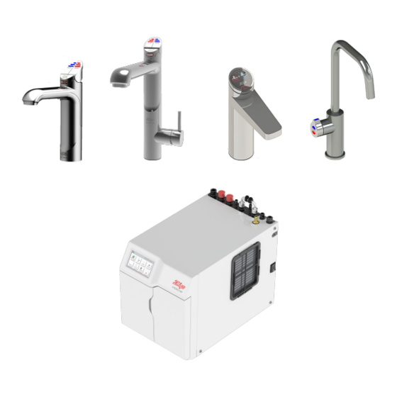
- Page 2 Tap Options The HydroTap appliance series offers a range of interchangeable taps to suit the customer’s needs. For ease of installation, it is recommended to fit the tap before installing the Command Centre. The Tap installation procedure is detailed in a separate Tap installation instructions, supplied with the Tap. For all operational features of the HydroTap, please refer to the CS User Guide 802269.
-
Page 3: Table Of Contents
Index HydroTap Specifications Installation Checklist ........................4 Important Safety Instructions ....................... 5 Warnings and Regulatory Information ..................6 Major Components and Accessories ................... 7 Technical Specification ........................ 8 Before Installation and Site Requirements ................... 9 STEP 1 - Measure and cut all the tap holes before fitting the taps Section 1 - (Refer to Tap installation instructions, supplied with the Tap) STEP 2 - Check for adequate ventilation... -
Page 4: Installation Checklist
Installation Checklist Thank you for purchasing a Zip HydroTap. Please read and follow these instructions carefully to ensure safe and trouble free service. Before Installation: Read the instructions and check if there is adequate space to mount all of the components. -
Page 5: Important Safety Instructions
Ensure the tap body is located so the tap outlet safely dispenses into the sink bowl area. Lifting Take care when lifting the Zip HydroTap unit. Some units may exceed safe lifting limits. If you feel this is beyond your personal capabilities, please seek assistance with the lift. The weights of the units are marked on the packaging. -
Page 6: Warnings And Regulatory Information
HydroTap until ready for first use. 10. For water taste and quality reasons, following any non-use period of more than 72 hours, Zip recommends to perform a system flush. Failure to flush the system may affect water quality. -
Page 7: Major Components And Accessories
Major Components and Accessories Parts supplied Description Accessories Description Font Kit for 1 x HydroTap Celsius; Arc & Cube Tap with hoses Models (Classic tap shown) Font Kit for Classic & 1 x HydroTap Elite Models Command Centre with air and water filters Replacement Filter 1 x Mains water... -
Page 8: Technical Specification
Technical Specifications Commercial Models: Glasses = Chilled Sparkling, Filtered of Chilled CSHA = Celsius Chilled Sparkling, Hot & Ambient Model Water per = Disabled lever controls, (Order as an option) Hour NOTE: The Glass measurement = 200ml Chilled water will continue to be dispensed after the rated capacity has been used, although this may be at slightly higher temperature. -
Page 9: Before Installation And Site Requirements
• Sufficient space in the cupboard to install all of the Command Centres in accordance with these Installation Instructions. Refer to technical specifications and section 4, for Installation instructions. • For Zip HydroTap CS & CSHA models, a 220-240V, 10A AC power outlet will be required. Note Note: Check all cable and hose lengths against inlet /outlet positions before proceeding (see section 4 for general layout). -
Page 10: Section 2 - Ventilation
Section 2 Ventilation When installing air flow ducts, the following tools will be required: • Jigsaw and 12mm drill • Keyhole or Wall Board saw. Ventilation for All Models Proper air circulation must be provided for all Chilled Sparkling models. The system will operate correctly only if the recommended air gaps are achieved during installation. -
Page 11: Alternative Ventilation
Ventilation A - Kickboard cut-out 1. Drill 4 pilot holes 12mm dia in corners 2. Finish cut-out using a Jigsaw and Keyhole or Wall board saw B - Cabinet floor cut-out 1. Drill two pilot holes 12mm dia. 2. Finish cut-out using a Jigsaw C - Cabinet floor cut-out 1. -
Page 12: Step 3 - Fit The Co Gas Cylinder Section 3 - Co Cylinder And Regulator 3.1 - Connect, Secure And Test The Co2 Gas Cylinder
Section 3 Cylinder STORAGE WARNING: A CO cylinder of mass 2.64kg must be installed in an open plan area or in an enclosed room, with a volume no less than 50m . If more than 1 gas cylinder containing CO is present within the same location, the recommended ventilated area should be in proportion to the number of gas cylinders stored in that location. -
Page 13: Co Regulator And Leak Test
Regulator This gauge shows the pressure in the bottle This gauge shows the adjustable limit (2.7- 3.0 bar) and indicates when the bottle is empty. Initial required for the HydroTap to function correctly bottle pressure will be 35-40 bar. Green zone Relief valve ON - OFF knob... -
Page 14: Section 4 - Command Centre Installation
Section 4 Command Centre Installation Hose and tube fitting • Remove all caps from the top of the Command 90° Bend end Centre (except the mixer caps) of Braided Hose Braided hose for • Only remove the mixer caps if a mixer tap is to be Mains Water Supply fitted. -
Page 15: Chilled Sparkling Models Cs175
Installation Instructions Chilled Sparkling Model - CS 175 Note: the hoses the hoses Note: need to have a need to have a constant downward constant downward gradient to the gradient to the Hydrotap to allow Hydrotap to allow all water to drain all water to drain back into the tanks. -
Page 16: Celsius Chilled Sparkling Model Csha175
Installation Instructions Celsius Chilled Sparkling Model - CSHA 175 Note: the hoses the hoses Note: need to have a need to have a constant downward constant downward gradient to the gradient to the Hydrotap to allow Hydrotap to allow all water to drain all water to drain back into the tanks. -
Page 17: Section 5 - Commissioning
Section 5 Commissioning Do not commission your HydroTap until it is ready to be used! The HydroTap is designed to be installed, commissioned and used within 48 hours. If your HydroTap is left idle before use, a filter change and sanitisation may be required. •... -
Page 18: Command-Centre Flush
Commissioning Command Centre Flush All G4 HydroTap products are currently sanitised after functional test at the factory. Due to the sanitisation process, residue from the sanitisation liquid might remain in the product, which requires the products to be flushed with fresh water at installation. 1. -
Page 19: Troubleshooting
Internal fault Call Zip Service Call an electrician, a plumber, or a Zip Service Provider for assistance, service, spare parts or enquiries. End of Life Disposal In order to help preserve our environment we ask that you dispose of this product correctly. Please contact your local city council for collection centre details. -
Page 20: Contact Details
Zip Water (Aust) Pty Ltd ABN 46 000 578 727 67-77 Allingham St, Condell Park NSW 2200 Postal: Locked Bag 80, Bankstown 1885 Australia zipwater.com | (+612) 9796 3100 | 1800 ZIP TAP (1800 947 827) WMKA21821 WMTS-105 The terms “Zip” and “HydroTap” are registered trade marks of Zip Water (Aust) Pty Ltd.
Need help?
Do you have a question about the HydroTap G4 and is the answer not in the manual?
Questions and answers
Fault saying water leak. We changed the zip filter and got that fault so removed the charcoal external filter as we thought it must be reducing the pressure. We replaced it with a 0.5 micron filter and got the same fault. Service pass code is 09037.