Zip HydroTap G4 Installation Instructions Manual
Filtered boiling, chilled and sparkling drinking water for residential kitchens and tea rooms, cs residential
Hide thumbs
Also See for HydroTap G4:
- User manual ,
- Installation instructions manual (40 pages) ,
- Installation and operating instructions manual (28 pages)
Table of Contents
Advertisement
Quick Links
Advertisement
Table of Contents

Subscribe to Our Youtube Channel
Related Manuals for Zip HydroTap G4


Summary of Contents for Zip HydroTap G4
- Page 1 Installation Instructions Zip HydroTap G4 ® Filtered Boiling, Chilled and Sparkling drinking water for Residential kitchens and tea rooms. CS Residential Affix Model Number Label Here 804052 804052 - CS Residential- Installation Instructions - Sept 2016 - v3.01 Page 1 of 20...
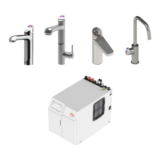
- Page 2 Tap options The HydroTap appliance series offers a range of interchangeable taps to suit the customer’s needs (See options below). For ease of installation, it is recommended to fit the tap before installing the undersink unit. The installation procedure for each of the taps is detailed in a separate tap installation instruction book No. 803341, supplied with the tap.
-
Page 3: Table Of Contents
Index HydroTap Specifications Installation check list ........................4 General product features ......................5 Important Safety Instructions ....................... 6 Warnings and Regulatory Information ..................7 Major components and Accessories .................... 8 Technical Specification ........................ 8 Before Installation and site requirements ..................9 Measure and cut all the tap holes before fitting the taps STEP 1 - Section 1 - See Tap Installation instructions, (supplied with the tap ) No. -
Page 4: Installation Checklist
Installation checklist Thank you for purchasing a Zip HydroTap. Please read and follow these instructions carefully to ensure safe and trouble free service. If service is required, please call 1800 638 633 Before Installation: Read the instructions and check if there is adequate space to mount all of the components. -
Page 5: General Product Features
Disabled use. The disabled levers are supplied with Braille caps for the visually impaired. Usage: The Zip HydroTap is intended for use in residential household and similar applications such as, Rural and urban residential Kitchens, Hotels, Motels, Bed and Breakfast and other residential type environments... -
Page 6: Important Safety Instructions
Ensure the tap body is located so the tap outlet safely dispenses into the sink bowl area. Lifting Take care when lifting the Zip HydroTap unit. Some units may exceed safe lifting limits. If you feel this is beyond your personal capabilities, please seek assistance with the lift. The weights of the units are marked on the packaging. -
Page 7: Warnings And Regulatory Information
Important Safety Instructions WARNINGS The Zip HydroTap unit must be earthed. The resistance of the earth connection from each exposed metal part must be less than 1 ohm. All Installation and service work must be completed by trained and suitably qualified Tradespeople. Faulty operation due to unqualified persons working on this product, or any other Zip product may void warranty coverage. -
Page 8: Major Components And Accessories
Major components and accessories Parts supplied Description Accessories Description 1 off 4 Font Kit for HydroTaps Arc & Cube Models with hoses (Classic tap shown) Font Kit for Classic & 1 off Elite Models HydroTap Undersink Unit with air and water filters 1 off Replacement Filter Mains water... -
Page 9: Before Installation And Site Requirements
Installation Instructions. Refer to technical specification for dimensions. Make allowance for a booster heater and / or water softener if required. Refer to section 3 & 4, for Installation instructions. • For Zip HydroTap CS and CSHA models, a 220-240Vac, 10A GPO will be required. Note Note: Check all cable and hose lengths against inlet /outlet positions before pro- ceeding (See section 5 for general layout). -
Page 10: Section 2 - Ventilation
Section 2 Ventilation When installing air flow ducts, the following tools will be required: • Jigsaw and 12mm Drill • Keyhole or Wall Board saw. Ventilation for All Models Proper air circulation must be provided for all Boiling and Chilled models. The system will operate correctly only if the recommended air gaps are achieved during Installation. - Page 11 Ventilation The following instructions are critical if there is insufficient cupboard air circulation. If the air flow, using the silicon door buffers, is insufficient, it will be necessary to fit a standard HydroTap vent kit, which ensures heat dissipation through natural convection via installed vents. For high use applications, where the cupboard space temperature is near 35°C, or higher, the inlet vent (See Item B below) and silicon buffers, need to be fitted.
- Page 12 Ventilation Typical Cut out procedure for Mark out and cut the air inlet and door outlet holes as shown Ensure the air inlet vent and air outlet vent are positioned at opposite ends of the same cupboard space. Fit the inlet vent, as shown and secure with 5 screws If required, fit the outlet vent, as shown in the hottest part (top) of the cupboard and secure with 4 screws Air inlet vent...
-
Page 13: Section 3 - Co Cylinder And Regulator 3.1 - Connect, Secure And Test The Co2 Gas Cylinder
Section 3 Cylinder WARNING: This cylinder mus be installed in an open plan area or in an enclosed room, with a volume no less than 20m If more than 1 gas cylinder containing CO is present within the same location, the recommended ventilated area should be in proportion to the number of gas cylinders stored in that location. -
Page 14: Step
Section 4 Undersink Unit Installation (Insertion and removal) John Guest fittings Be careful when cutting the poly tube so that there are no rough edges and that the tube is not distorted. Use a sharp knife to ensure the tube has a clean, straight edge. Do not cut at an angle. Remove any swarf or unwanted material. -
Page 15: Test For Gas Leaks
Connections & Leak Testing pressure set zone: 2.7-3.0 bar IMPORTANT: After replacing a bottle or after mak- ing a gas connection, check for gas leaks: Stage1: Turn the gas OFF Using soapy water applied with a sponge, or with a brush, cover all of the gas joints with a liberal amount of suds. -
Page 16: Chilled Sparkling Models Cs175
Installation Instructions CS Models Note: - Mains hose length is 750mm - Plug and Cord length is 1800mm Position the under sink unit close to the outlet tap, within reach of the hose and cord lengths supplied Note: All All Note: silicon tubes silicon tubes... -
Page 17: Section 5 - Commissioning
Section 5 Commissioning The HydroTap is now ready to be commissioned. • Turn ON the water and gas and check for any leaks. • Turn the power ON at the GPO and at the side of the undersink unit • Familiarise yourself with the operation of the Tap, in preparation for use (See User Manual) •... -
Page 18: Filter Flush
Commissioning Filter Flush Have a 10L bucket or similar container (not supplied) at the ready to hold a quantity of water that will be ejected while the Filter Flush Mode is in operation. Open the filter access door on the front of the HydroTap and the filter cartridge will be exposed. -
Page 19: Trouble Shooting
Flow Sensor Fault Internal fault Call Zip Service Call an electrician, a plumber, or Zip for a free call in Australia on 1800-638-633 for assistance, service, spare parts or enquiries. End of Life Disposal In order to help preserve our environment we ask that you dispose of this product correctly. Please contact your local city council for collection centre details. -
Page 20: Contact Details
The standard cup referred to in this publication is 167 ml (6 fl oz). The standard glass is 200 ml (7 fl oz). The terms “Zip” and “HydroTap” are registered trade marks of Zip Heaters (Aust) Pty Ltd. Zip products described in this publication are manufactured under one or more of the following patents: AU675601, AU637412, AU635979, GB0422305, GB2065848, US4354049, US5103859, US5099825 and SA2006/08043.
Need help?
Do you have a question about the HydroTap G4 and is the answer not in the manual?
Questions and answers