Table of Contents
Advertisement
Quick Links
Download this manual
See also:
Programming Manual
Advertisement
Table of Contents

Related Manuals for ITech IT8300 Series


Summary of Contents for ITech IT8300 Series
- Page 1 Regenerative DC Electronic Load Series IT8300 User’s Manual Model: IT8311/IT8312/IT8321/IT8322/IT8331/IT8332/ IT8341/IT8342/IT8351/IT8352/IT8361/IT8362/IT8371 /IT8372/IT8381/IT8382/IT8391/IT8392 Revision: V1.0...
- Page 2 Notices Safety Notices Warranty © Itech Electronic, Co., Ltd. 2017 The materials contained in this No part of this manual may be document are provided “as is” , and reproduced in any form or by any means is subject to change, without prior (including electronic storage and notice, in future editions.
-
Page 3: Warranty Service
ITECH, and ITECH will be responsible for return freight. If the product is sent to ITECH for warranty service from other countries, the customer will be responsible for all the freight, duties and other taxes. Limitation of Warranty... -
Page 4: Safety Precautions
In case of failure to follow these precautions or specific warnings in other parts of the manual, violation against the safety standards related to the design, manufacture and purpose of the instrument will occur. If the user does not follow these precautions, ITECH will bear no responsibility arising there from. ... -
Page 5: Regulation Tag
According to the equipment classification in Annex I of the WEEE directive, this instrument belongs to the “Monitoring” product. If you want to return the unnecessary instrument, please contact the nearest sales office of ITECH. Copyright © ITECH Electronics Co., Ltd. -
Page 6: Compliance Information
Connection of the instrument to a test object may produce radiations beyond the specified limit. Use high-performance shielded interface cable to ensure conformity with the EMC standards listed above. Safety Standard IEC 61010-1:2010/ EN 61010-1:2010 Copyright © ITECH Electronics Co., Ltd. -
Page 7: Table Of Contents
NTERFACE 4.3 LAN I ..............................39 NTERFACE 4.4 CAN I ..............................39 NTERFACE 4.5 RS485 I ..............................40 NTERFACE CHAPTER5 TECHNICAL SPECIFICATIONS ......................41 CHAPTER6 ROUTINE MAINTENANCE ......................68 6.1 S ................................68 TEST Copyright © ITECH Electronics Co., Ltd. - Page 8 IT8300 User Manual 6.2 R ............................68 OUTINE AINTENANCE 6.3 C ITECH E ............................68 ONTACT NGINEER 6.4 R ..............................69 ETURN FOR EPAIR APPENDIX................................71 ........................ 71 PECIFICATIONS OF ED AND LACK ABLES Copyright © ITECH Electronics Co., Ltd.
-
Page 9: Chapter1 Inspection And Installation
Note After confirming that package contents are consistent and correct, please appropriately keep package box and related contents. The package requirements should be met when the instrument is returned to factory for repair. Copyright © ITECH Electronics Co., Ltd. -
Page 10: Instrument Size Introduction
The instrument should be installed at well-ventilated and rational-sized space. Please select appropriate space for installation based on the electronic load size. IT8300(3U)series Overall dimensions: Width: 483 mm Height: 151.3 mm Depth: 778.11 mm Detailed dimensional drawings Copyright © ITECH Electronics Co., Ltd. - Page 11 Inspection and Installation IT8300(6U)series Overall dimensions: Width: 483 mm Height: 348.84 mm Depth: 776.61 mm Detailed dimensional drawings Copyright © ITECH Electronics Co., Ltd.
- Page 12 Inspection and Installation IT8300 (15U) series, Overall dimensions: 550 mmW x 800mmD x 908mmH, Refer to the following dimension drawing: Copyright © ITECH Electronics Co., Ltd.
- Page 13 Inspection and Installation IT8300 (24U) series, Overall dimensions: 550 mmW x 900.1mmD x 1291.24mmH, Refer to the following dimension drawing: Copyright © ITECH Electronics Co., Ltd.
-
Page 14: Connecting The Power Cord
Connecting the Power Cord The IT8300 series electronic load AC input needs to connect to the three-phase power supply with protective grounding. Please ensure the power switch of the instrument is turned OFF. -
Page 15: Connecting Test Cables (Optional)
Always use test cables provided by ITECH to connect the equipment. If test cables from other factories are used, please check that the test cable can withstand maximum current. -
Page 16: Chapter2 Quick Start
Quick Start Chapter2 Quick Start This Chapter will introduce power-on check steps of IT8300 Series to ensure normal start-up and usage under initialization status of the load. Besides, to facilitate usage, this part also displays the functions of front board, rear board... -
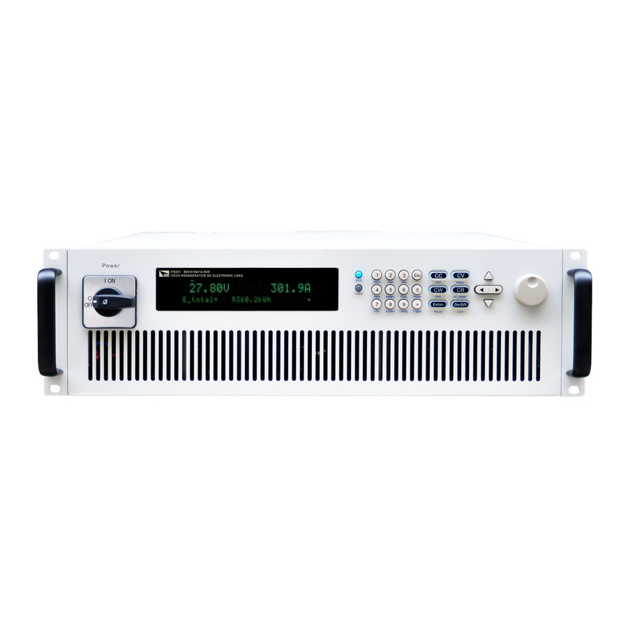
Page 17: Front Panel Introduction
80V/3570A/73.5KW 800V/420A/73.5KW 2.2 Front Panel Introduction The 3U models of IT8300 Series electronic load have same front panels. Other models, have same panels as 3U Model. The front panel diagram and function key diagram of 3U Model are as follows. -
Page 18: Fast Function Key
Trigger key, to start up triggering functions. Shift + CC (OCP) To operate OCP test function. Shift + CV (Setup) To set specific parameters of constant voltage, constant current, constant resistance and constant power. Copyright © ITECH Electronics Co., Ltd. -
Page 19: Function Description Of Vfd Status Indicators
Serial request query. Shift Shift key is pressed. 2.6 Rear Panel Introduction Schematic Diagram of Rear Panel of IT8300 series (3U) electronic load. RS485 communication interface and CAN communication interface LAN communication interface RS232 communication interface USB communication interface... -
Page 20: Power-On Selftest
Power Switch Introduction User can rotate the power switch of IT8300 series electronic load directly to turn on or turn off the instrument. The sketch of Powe switch is as follows. Copyright © ITECH Electronics Co., Ltd. - Page 21 Yes => 3 No => Please check the Power key to start power and check whether the exception is removed. Check whether set power voltage of electronic load is matched with the power supply voltage. Copyright © ITECH Electronics Co., Ltd.
-
Page 22: Chapter3 Function And Features
Rotate adjusting knob to set constant current value. Use numeric keys to input current value and press [Enter] key to confirm set constant current value. moving cursor and press to adjust values at corresponding positions. Copyright © ITECH Electronics Co., Ltd. - Page 23 Under CV mode, the electronic load will consume sufficient current to maintain the input voltage at setting voltage. As shown in Fig. 3-2. Load voltage Set voltage Load current CV mode Fig. 3-2 Voltage-Current Relation Schema under CV Mode Copyright © ITECH Electronics Co., Ltd.
- Page 24 Set resistance value = voltage / current Load voltage Load current CR Mode Fig. 3-3 Voltage-Current Relation Schema under CR Mode Under CR mode, the electronic load provides three ways to modify constant resistance. Copyright © ITECH Electronics Co., Ltd.
- Page 25 Load current CW mode Fig. 3-4 Voltage-Current Relation Schema under CW Mode Under CW mode, the electronic load provides three ways to modify constant power. Rotate adjusting knob to set constant power value. Copyright © ITECH Electronics Co., Ltd.
-
Page 26: Input Control Function
[Shift] + 1(Short) key to switch short circuit status. The short circuit status does not influence existing setting value. When the short circuit operation is switched back to OFF status, the load returns back to original setting status. Copyright © ITECH Electronics Co., Ltd. -
Page 27: System Menu Function (System)
Socket Port setting RS485 Select the RS485 communication interface. 4800, 8, N non parity check, 1 9600 O even parity check, 2 19200 E odd parity check 38400 57600 115200 Select the CAN communication interface. Copyright © ITECH Electronics Co., Ltd. -
Page 28: Configuration Menu Function (Config)
Von point latch state, ON /OFF Point= 2V Set the Von value Set hardware protective power P-Limit value. Point=150W Set the maximum power. Protect I-Protect Set software current protection. Start function. Set software current protective Point=30A value. Copyright © ITECH Electronics Co., Ltd. -
Page 29: Observe Power Grid Information
There are three triggering methods to trigger the tested instrument. Optional triggering sources of triggering function of electronic load comprise: Manual trigger: when key trigger is valid, press [Shift] + .(Trigger) key and Copyright © ITECH Electronics Co., Ltd. -
Page 30: Dynamic Test Function
Press [Shift] + 2 (Tran) keys. TRANSITION Operate key and move to Off. Press [Enter] key and select Continuous. Press [Enter] key. TRANSITION Continuous Pulse Toggle Copyright © ITECH Electronics Co., Ltd. - Page 31 Under pulse mode, after enabling dynamic test operation, the load will switch to B value after receipt of a trigger signal and switch back to A value after maintaining B for pulse width time. Copyright © ITECH Electronics Co., Ltd.
- Page 32 10. Enter the dynamic test mode. 10.00V 0.0A 0 TRAN 11. Press [On/Off] key to open input and press [Shift] + . (Trigger) key. The load will switch after receipt of every trigger signal. The load will Copyright © ITECH Electronics Co., Ltd.
- Page 33 High-Rate and press [Enter] key. TRANSITION High-Rate Low-Rate Set ascending slope and press [Enter] key. TRANSITION Rise up=2.0A/mS Set descending slope and press [Enter] key. TRANSITION Fall down=2.0A/mS Set A value and press [Enter] key. TRANSITION Level A=1.0A Copyright © ITECH Electronics Co., Ltd.
-
Page 34: Ocp Test Function
3.11 OCP test function The IT8300 series electronic load is provided with overcurrent protection test function (OCP). Under OCP test mode, when input voltage reached Von value, delay for a while for the electronic load to latch. Ascend value by step value at regular interval. -
Page 35: Opp Test Function
STOP 3.12 OPP test function The IT8300 series electronic load is provided with overpower protection test function (OPP). Under OPP test mode, when input voltage reached Von value, delay for a while for the electronic load to latch. Ascend value by step value at regular interval. -
Page 36: Battery Discharge Test Function
STOP 3.13 Battery discharge test function In the IT8300 series electronic load, constant current mode is applied for discharge test with programmatic setting of stop voltage/capacity/discharging time If stop voltage is set as the stop condition, the system determines whether the battery is about to reach the set threshold value or unsafe status when the battery voltage is low, and if yes, an automatic stop will be activated. -
Page 37: Configuration Save Function
Group 0 means you can recall data saved in 1-10 groups. Group 1 means you can recall data saved in 11-20 groups. Group2-Group 9 can be concluded in the same manner. Copyright © ITECH Electronics Co., Ltd. -
Page 38: Von Function
Von Point and Hysteresis, the load is still loaded; only when the power voltage is lower than the difference between Von Point and Hysteresis, the load will unload. Load working range when VON LIVING is started Copyright © ITECH Electronics Co., Ltd. -
Page 39: Protective Function
PS bits of the status register will be set and keep till reset. The setting method as follows: Press [Shift] + 9(Config) to enter configuration menu setting screen. Press to move to the Protect and press [Enter]. Copyright © ITECH Electronics Co., Ltd. - Page 40 When load temperature is decreased to protection point (75 ° C), the load automatically restored from the protection state, and OTP need to be manually cleared, the load into the standby state. Clear overtemperature protection: Copyright © ITECH Electronics Co., Ltd.
-
Page 41: List Operation
RAM. Refer to examples below to know how to execute List operation through board. It is assumed that output voltage and current of the tested instrument are 10V and 3A respectively and the load is under CC mode. Copyright © ITECH Electronics Co., Ltd. - Page 42 EDIT LIST Step 01 Width=5.00S Edit current value in step 2 and press [Enter] key. EDIT LIST Step 02 Level=2.0A Edit slope in step 2 and press [Enter] key. EDIT LIST Step 02 Rate=0.1A/mS Copyright © ITECH Electronics Co., Ltd.
-
Page 43: Terminal Function Of Rear Panel
Press [On/Off] key to open input and press [Shift] + .(Trigger) key (Triggering key) List operation. 3.18 Terminal function of rear panel Terminals on IT8300 rear panel comprise remote sensor terminal, external analog control terminal and current monitoring terminal. Terminal schematic (as shown below): Copyright © ITECH Electronics Co., Ltd. - Page 44 Press [Shift] + 9(Config) keys to enter menu. Operate key and select Remote-Sense. Press [Enter] key. Select ON and start Sense function. Set load in remote sense measurement mode. Remote sense measurement is connected. Refer to figure below for detailed wiring. Copyright © ITECH Electronics Co., Ltd.
-
Page 45: Auto Test Function
Connecting the terminal as follow. 3.19 Auto Test Function The IT8300 series electronic load delivers strong auto test functions, which can analog several tests. A total of 10 groups of test files can be edited, and each group test file has 10 steps. Therefore, a maximum of 100 steps can be edited and saved in EEPROM. - Page 46 10. Set unloading time of step 2. If 2S is required, directly press 2 key. Press [Enter] key. EDIT PROGRAM SEQ02 Off Time=2.0S 11. Set test delay time of step 2. If 1S is required, directly press 1 key. Press [Enter] key. Tpf is delay time before measurement. Copyright © ITECH Electronics Co., Ltd.
- Page 47 It is assumed that step 1 edits CC mode as follows: current: 2A, maximum voltage value: 10V, and minimum voltage value: 2V. Press the [CC] key to set the current value as 2A. Press the [Shift]+[CV](Setup) keys to enter the parameter setting page. Copyright © ITECH Electronics Co., Ltd.
- Page 48 Set the maximum current value, and enter the [Enter] key. Constant Voltage High=5.0A Set the minimum current value, and enter the [Enter] key. Constant Voltage Low=0.0A After the parameter settings are complete, the page is shown as follows. 10.00V 0.0A CV=3.00V Copyright © ITECH Electronics Co., Ltd.
-
Page 49: Parallel Function
Press [Shift] + . (Trigger) key. Operate auto test file 1. Press [Shift] + 0 (Pause) key to pause auto test. Press key for next step. 3.20 Parallel Function Maximum power of the IT8300 series load is 73.5KW. In IT8300 series load, Copyright © ITECH Electronics Co., Ltd. - Page 50 10. Select the Slave and press [Enter], the panel displays as follows: SWITCH TO SLAVE ? 11. Select the Yes and the panel displays as follows: ON SLAVE MODE Please Power Off ! Copyright © ITECH Electronics Co., Ltd.
- Page 51 Remove System BUS connecting 3 instruments. Power on 3 instruments respectively. Press the composite key (Shift+Local+Esc) on the front panel of 3 single instruments, and the single instrument will automatically switch to Single Mode. Copyright © ITECH Electronics Co., Ltd.
-
Page 52: Chapter4 References Of Load Communication Interfaces
References of Load Communication Interfaces Chapter4 References of Load Communication Interfaces IT8300 series electronic load is provided with five communication interfaces to communicate with a computer for selection, including RS232, USB, LAN, CAN and RS485. 4.1 RS232 Interface Cable connection load with both ends of COM interface (DB9) and computer. -
Page 53: Usb Interface
The interface receives the command MsgID=TRIGGER USBTMC and conveys the TRIGGER command to the functional layer. The functions of load USB488 device are as follows: Capable to read all common SCPI commands. SR1 enabled. RL1 enabled. Copyright © ITECH Electronics Co., Ltd. -
Page 54: Lan Interface
The PC and load have same Baud rate. Appropriate interface pin or adapter is used, as described in CAN connector. The interface cable is correctly connected (CAN_H to CAN_H, CAN_L to CAN_L). Check whether 120 Ω terminal resistance is connected. Copyright © ITECH Electronics Co., Ltd. -
Page 55: Rs485 Interface
Through front board [Shift] + 8(System), the user can set the Baud rate, Data bit, Stop bit and check. And the operation method is same as RS232. RS485 interface pin is as follows. description A cable of RS485 interface B cable of RS485 interface RS485 interface pin Copyright © ITECH Electronics Co., Ltd. -
Page 56: Chapter5 Technical Specifications
Technical Specifications Chapter5 Technical Specifications This chapter will introduce the rated voltage, current, power and many other main parameters of IT8300 series. Parameter IT8311 V1.3 Input parameter Input voltage 0~80V Input current 0~170A Rated value Input power 0~3.5kW ( 0~40 ℃) Min. - Page 57 Range 0~20A Resolution 10mA CC mode Accuracy <0.4% I Range 0~800V CV mode Resolution 100mV Accuracy <0.3% U 0.9~3000Ω Range 0.001Ω(R<10Ω);0.01Ω(10Ω≤R<100Ω);0.1Ω(100Ω≥R<1000Ω);1Ω(R≥100 CR mode Resolution 0Ω) Accuracy *2%:(0.9~1000Ω); R *5%:(1000~3000Ω); Range 0~3.5kW CP mode Resolution Copyright © ITECH Electronics Co., Ltd.
- Page 58 766.6mm*483mm*132.8mm Weight( net) 26kg Remarks: Current and voltage is not less than 10% of full scale in resistance test. The scope of read-back resistance is described as follows: 0.9~1000Ω Lower limit value: 1/(1/R+(1/R)*0.02+0.002) Copyright © ITECH Electronics Co., Ltd.
- Page 59 External programming voltage 0-10V corresponds to current 0-340A Current Monitoring Current 0-340A corresponds to external monitoring voltage 0-10V Output parameter Output voltage range 190VAC~260VAC OVP Protection 260VAC UVP Protection 190VAC Output frequency 45Hz~65Hz range Copyright © ITECH Electronics Co., Ltd.
- Page 60 <0.4% I Range 0~800V CV mode Resolution 100mV Accuracy <0.3% U 0.6~2000Ω Range 0.001Ω(R<10Ω);0.01Ω(10Ω≤R<100Ω);0.1Ω(100Ω≥R<1000Ω);1Ω(R≥100 CR mode Resolution 0Ω) Accuracy *2%:(0.6~600Ω); R *5%:(600~2000Ω); Range 0~7kW CP mode Resolution Accuracy <1.3% P Dynamic Rising slope 50A/ms Copyright © ITECH Electronics Co., Ltd.
- Page 61 Current and voltage is not less than 10% of full scale in resistance test. The scope of read-back resistance is described as follows: 0.6~600Ω Lower limit value: 1/(1/R+(1/R)*0.02+0.002) Upper limit value: 1/(1/R-(1/R)*0.02-0.002) 600~2000Ω Copyright © ITECH Electronics Co., Ltd.
- Page 62 External programming voltage 0-10V corresponds to current 0-510A Current Monitoring Current 0-510A corresponds to external monitoring voltage 0-10V Output parameter Output voltage range 190VAC~260VAC OVP Protection 260VAC UVP Protection 190VAC Output frequency 45Hz~65Hz range Maximum output 17Aac current (rms) Copyright © ITECH Electronics Co., Ltd.
- Page 63 CV mode Resolution 100mV Accuracy <0.3% U 0.3~1000Ω Range 0.001Ω(R<10Ω);0.01Ω(10Ω≤R<100Ω);0.1Ω(100Ω≥R<1000Ω);1Ω(R≥100 CR mode Resolution 0Ω) Accuracy *2%:(0.3~300Ω); R *5%:(300~1000Ω); Range 0~10.5kW CP mode Resolution Accuracy <1.3% P Rising slope 50A/ms Dynamic Falling slope 50A/ms Dynamic 500Hz Copyright © ITECH Electronics Co., Ltd.
- Page 64 Current and voltage is not less than 10% of full scale in resistance test. The scope of read-back resistance is described as follows: 0.3~300Ω Lower limit value: 1/(1/R+(1/R)*0.02+0.002) Upper limit value: 1/(1/R-(1/R)*0.02-0.002) 300~1000Ω Lower limit value: 1/(1/R+(1/R)*0.05+0.002) Copyright © ITECH Electronics Co., Ltd.
- Page 65 Current 0-1020A corresponds to external monitoring voltage 0-10V Output parameter Output voltage range 190VAC~260VAC OVP Protection 260VAC UVP Protection 190VAC Output frequency 45Hz~65Hz range Maximum output 34Aac current (rms) Power factor >0.99 (lead or lag) Copyright © ITECH Electronics Co., Ltd.
- Page 66 Resolution 100mV Accuracy <0.3% U 0.15~500Ω Range 0.001Ω(R<10Ω);0.01Ω(10Ω≤R<100Ω);0.1Ω(100Ω≥R<1000Ω);1Ω(R≥100 CR mode Resolution 0Ω) Accuracy *2%:(0.15~100Ω); R *5%:(100~500Ω); Range 0~21kW CP mode Resolution Accuracy <1.3% P Rising slope 100A/ms Falling slope 100A/ms Dynamic Dynamic 500Hz Frequency Copyright © ITECH Electronics Co., Ltd.
- Page 67 Current and voltage is not less than 10% of full scale in resistance test. The scope of read-back resistance is described as follows: 0.15~100Ω Lower limit value: 1/(1/R+(1/R)*0.02+0.002) Upper limit value: 1/(1/R-(1/R)*0.02-0.002) 100~500Ω Lower limit value: 1/(1/R+(1/R)*0.05+0.002) Upper limit value: 1/(1/R-(1/R)*0.05-0.002) Copyright © ITECH Electronics Co., Ltd.
- Page 68 Output frequency 45Hz~65Hz range Maximum output 51Aac current (rms) Power factor >0.99 (lead or lag) DC component -0.5A~+0.5A Harmonic THDI <3% Islanding protection Active islanding protection Environment parameter Working temperature 0~40℃ Storage temperature -20~70℃ Copyright © ITECH Electronics Co., Ltd.
- Page 69 Resolution Accuracy <1.3% P Rising slope 100A/ms Falling slope 100A/ms Dynamic Dynamic Frequency Input read-back value Range 0~180A Readback Resolution 10mA current Accuracy <0.4% I Range 0~800V Readback Resolution 100mV voltage Accuracy <0.3% U Copyright © ITECH Electronics Co., Ltd.
- Page 70 Lower limit value: 1/(1/R+(1/R)*0.02+0.002) Upper limit value: 1/(1/R-(1/R)*0.02-0.002) 80~333Ω Lower limit value: 1/(1/R+(1/R)*0.05+0.002) Upper limit value: 1/(1/R-(1/R)*0.05-0.002) Parameter IT8361 V1.3 Input parameter Input voltage 0~80V Rated value Input current 0~2040A ( 0~40 ℃) Input power 0~42kW Copyright © ITECH Electronics Co., Ltd.
- Page 71 >0.99 (lead or lag) DC component -0.5A~+0.5A Harmonic THDI <3% Islanding protection Active islanding protection Environment parameter Working temperature 0~40℃ Storage temperature -20~70℃ Noise 60dB Efficiency Maximum efficiency (Fully loaded power of 92.5% maximum input voltage) Communication Copyright © ITECH Electronics Co., Ltd.
- Page 72 Range 0~240A Readback Resolution 10mA current Accuracy <0.4% I Range 0~800V Readback Resolution 100mV voltage Accuracy <0.3% U Range 0~42kW Readback Resolution power Accuracy <1.3% P Protection range OCP Protection 252A OVP Protection 810V Copyright © ITECH Electronics Co., Ltd.
- Page 73 IT8371 V1.2 Parameter Input parameter Input voltage 0~80V Input current 0~2550A Rated value Input power 0~52.5kW ( 0~40 ℃) Min. operating 1V at 2550A voltage Range 0~2550A Resolution 100mA CC mode Accuracy <0.4% Imax Copyright © ITECH Electronics Co., Ltd.
- Page 74 >0.99 (lead or lag) DC component -0.5A~+0.5A Harmonic THDI <3% Islanding protection Active islanding protection Environment parameter Working temperature 0~40℃ Storage temperature -20~70℃ Noise 60dB Efficiency Maximum efficiency (Fully loaded power of 92.5% maximum input voltage) Copyright © ITECH Electronics Co., Ltd.
- Page 75 Input read-back value Range 0~300A Readback Resolution 10mA current Accuracy <0.4% I Range 0~800V Readback Resolution 100mV voltage Accuracy <0.3% U Range 0~52.5kW Readback Resolution power Accuracy <1.3% P Protection range OCP Protection 315A Copyright © ITECH Electronics Co., Ltd.
- Page 76 Upper limit value: 1/(1/R-(1/R)*0.05-0.002) IT8381 V1.2 Parameter Input parameter Input voltage 0~80V Input current 0~3060A Rated value Input power 0~63kW ( 0~40 ℃) Min. operating 1V at 3060A voltage Range 0~3060A CC mode Resolution 100mA Copyright © ITECH Electronics Co., Ltd.
- Page 77 102Aac current (rms) Power factor >0.99 (lead or lag) DC component -0.5A~+0.5A Harmonic THDI <3% Islanding protection Active islanding protection Environment parameter Working temperature 0~40℃ Storage temperature -20~70℃ Noise 60dB Efficiency Maximum efficiency 92.5% Copyright © ITECH Electronics Co., Ltd.
- Page 78 Falling slope 100A/ms Dynamic Dynamic Frequency Input read-back value Range 0~360A Readback Resolution 10mA current Accuracy <0.4% I Range 0~800V Readback Resolution 100mV voltage Accuracy <0.3% U Range 0~63kW Readback Resolution power Accuracy <1.3% P Copyright © ITECH Electronics Co., Ltd.
- Page 79 Lower limit value: 1/(1/R+(1/R)*0.05+0.002) Upper limit value: 1/(1/R-(1/R)*0.05-0.002) IT8391 V1.2 Parameter Input parameter Input voltage 0~80V Input current 0~3570A Rated value Input power 0~73.5kW ( 0~40 ℃) Min. operating 1V at 3570A voltage Copyright © ITECH Electronics Co., Ltd.
- Page 80 45Hz~65Hz range Maximum output 119Aac current (rms) Power factor >0.99 (lead or lag) DC component -0.5A~+0.5A Harmonic THDI <3% Islanding protection Active islanding protection Environment parameter Working temperature 0~40℃ Storage temperature -20~70℃ Noise 60dB Copyright © ITECH Electronics Co., Ltd.
- Page 81 <1.3% P Rising slope 100A/ms Falling slope 100A/ms Dynamic Dynamic Frequency Input read-back value Range 0~420A Readback Resolution 10mA current Accuracy <0.4% I Range 0~800V Readback Resolution 100mV voltage Accuracy <0.3% U Readback Range 0~73.5kW Copyright © ITECH Electronics Co., Ltd.
- Page 82 The scope of read-back resistance is described as follows: 0.045~10Ω Lower limit value: 1/(1/R+(1/R)*0.02+0.002) Upper limit value: 1/(1/R-(1/R)*0.02-0.002) 10~140Ω Lower limit value: 1/(1/R+(1/R)*0.05+0.002) Upper limit value: 1/(1/R-(1/R)*0.05-0.002) *The above specifications may be subject to change without prior notice. Copyright © ITECH Electronics Co., Ltd.
-
Page 83: Chapter6 Routine Maintenance
In case of instrument failure, please perform the following self-checks. If the instrument can be recovered by simple check, the cost and time can be saved. Before contacting the engineer of ITECH, please check the following items. Check whether the instrument is powered on. -
Page 84: Return For Repair
SN collection ITECH will improve the product performance, availability and reliability from time to time. The service personnel of ITECH will record the changes of each instrument, and all the relevant information will be identified according to the SN. The SN will be used as the tracking ID of the instrument returned for repair. - Page 85 Routine Maintenance generated by styrene particles or penetration of styrene particles into holes of the rear panel. Read the requirements of transportation costs of warranty services in the foreword before delivery. Copyright © ITECH Electronics Co., Ltd.
-
Page 86: Appendix
Specifications of Red and Black Test Cables ITECH provides you with optional red and black test cables, which individual sales and you can select for test. For specifications of ITECH test cables and maximum current values, refer to the table below. - Page 87 Contact US Thank you for purchasing ITECH products. If you have any doubt about this product, please contact us as follows. 1. Please refer to the CD-ROM of related user’s manual in package. 2. Visit ITECH website www.itechate.com . 3. Select the most convenient contact for further consultation.
Need help?
Do you have a question about the IT8300 Series and is the answer not in the manual?
Questions and answers