
Related Manuals for ITech IT8518B


Summary of Contents for ITech IT8518B
- Page 1 USER’S GUIDE Programmable DC Electronic Load Models IT8518 This user manual is applicable to: Model: IT8518B/IT8518C/IT8518E/IT8518F Copyright 2010 All Rights Reserved Ver2,0/Jan, 2010/ IT8500-401 http://www.Datasheet4U.com...
-
Page 2: Table Of Contents
Introduction ···················································· QUICK REFERENCE THE FRONT PANEL ..........THE REAR PANEL ........FRONT PANEL ANNUNCIATORS ......... KEY PAD ..........IMMEDIATE ACTION KEYS ........... MENU OPERATION ..........··················································· GENERAL INFORMATION DOCUMENT ORIENTATION ..........GETTING STARTED MAP ..........OPTIONS AND ACCESSORIES ......... Options .......... - Page 3 Introduction Items Supplied ..........Cleaning ..........LOCATION ........... Installation ..........BENCH OPERATION ..........INPUT CONNECTIONS ..........Power Cord ......··················································· TURN-ON CHECKOUT INTRODUCTION ........... CHECKOUT PROCEDURE .......... In Case of Trouble ..........················································· FRONT PANEL OPERATION EXAMPLE ........... I-set (set up a constant current from 0 to Max current ) ..
- Page 4 Warranty Information Certification We certify that this product met its published specifications at time of shipment from the factory. Warranty This hardware product is warranted against defects in material and workmanship for a period of ONE year from date of delivery. IT8500 series electronic load for use with a hardware product and when properly installed on that hardware product, are warranted not to fail to execute their programming instructions due to defects in material and workmanship for a period of 90 days from date of delivery.
- Page 5 Safety Summary The following general safety precautions must be observed during all phases of operation of this instrument. Failure to comply with these precautions or with specific warnings elsewhere in this manual violates safety standards of design, manufacture, and intended use of the instrument .We assumes no liability for the customer’s failure to comply with these requirements.
- Page 6 DO NOT SERVICE OR ADJUST ALONE Do not try to do some internal service or adjustment unless another person capable of rendering first aid resuscitation is present. Safety Symbols Direct current Alternating current Both direct and alternating current Protective earth (ground) terminal Caution (refer to accompanying documents) Warning: The WARNING sign denotes a hazard.
-
Page 7: Quick Reference
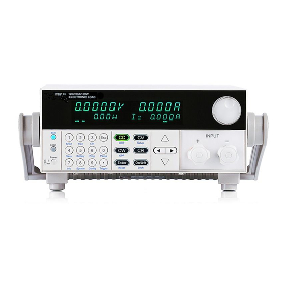
Quick Reference Q u i ck Re f ere n ce T h e F r o n t Pa n el 16-character display shows voltage and current measurements Rotary knob Power switch ON/OFF Entry keys:(numeric keys) Enter values Increasing or decreasing the setup values Menu commands Keypad: Enable/disable input. -
Page 8: The Rear Panel
Quick Reference T he Rear Pan e l Input terminals 3 Pin IEC320 ac input connector Fuse Power switch (110V / 220V) 9-Pin COM port interface connector 4 Pin Trigger and Remote sensing connectors F r o n t P ane l An nu n ci a to rs Front Panel Annunciators Trigger Indicates that the electronic load is waiting... -
Page 9: Key Pad
Quick Reference Key P ad I-set V-set POWER Tran P-set R-set ENTER Store Recall S-Tran Menu On/Off Shift Local Battery Short Trigger 0 through 9 are used for entering numeric values. Decimal point. The escape key. It may used to exit any working state. Choosing CC mode and setup the input current of regulation current mode. -
Page 10: Menu Operation
Quick Reference Me nu O p era ti o n Press Menu to indicate operation mode .View the menu in VFD and using ▽ and △ to scroll through the completely menu list as following. If press key, you could get the selected menu function. Enter Press back to the previous menu selection page. - Page 11 GENERAL INFORMATION BAUDRATE SET Setting baud rate. 4800<DEFAULT> 9600 19200 38400 COMM. PARITY SET Command parity setting. NONE<DEFAULT> EVEN ADDRESS SET Setting communication Flow mode KEY LOCK SET Setting keypad password. EXIT SYSTEM SET MAX CURRENT SET Setup the maximum current. Setup the maximum power.
-
Page 12: General Information
GENERAL INFORMATION G en era l I nf or ma t io n Doc u me n t Orie n ta t io n This manual describes the operation of the IT8500 series electronic loads. Unless otherwise noted,all units will be referred to by the description "electronic load" throughout this User's manual. The following documents and software are shipped with your electronic load. -
Page 13: Options And Accessories
GENERAL INFORMATION O p ti on s an d Ac c es so ri es Options IT-E131 isolated communication cable: This cable converts the electronic load’s series port (TTL 5V level) to PC RS232 interface. IT-E132 isolated communication cable: This cable converts the electronic load’s series port (TTL 5V level) to PC USB interface. -
Page 14: Front Panel Controls
GENERAL INFORMATION F r o n t P ane l Co n tr ol s The front panel has keyboard controls for setting the input voltage, current and resistance. The panel display provides digital readouts of a number of functions including the inputs. Annunciators displaythe operating status of the electronic load. -
Page 15: Constant Voltage (Cv) Mode
GENERAL INFORMATION SLOPE LOAD RESISTANCE CURRENT SETTING LOAD INPUT VOLTAGE CONSTANT RESISTANCE MODE Con stan t Vo lt a ge ( C V) M o de In this mode, the electronic load will attempt to sink enough current to control the source voltage to the programmed value. -
Page 16: Transient Operation
GENERAL INFORMATION Con stan t Po wer ( CW ) M o d e In this mode, the electronic loads will consumption power accordance with the programmed value regardless of the input voltage. The CW mode can be set with front panel keys. The CW mode parameters are discussed in the following paragraphs. -
Page 17: Trigger Mode
GENERAL INFORMATION Tr i gg er M od e Switching the state between value A and value B once receiving a triggering signal Toggled Transient Operation L i st O p erat io n List mode lets you generate complex sequences of input changes with rapid, precise timing, which may be synchronized with internal or external signals. -
Page 18: Triggered Operation
GENERAL INFORMATION Tri g g er ed Ope ra ti o n The electronic load has various triggering modes to allow synchronization withother test equipment or events. Such as: Keypad triggering mode: Press to trigger the electronic load. Trigger Shift TTL triggering mode: Send a high pulse with a constant time more than 5m Sec to the trigger terminals in rear panel to trigger the electronic load. -
Page 19: Input On/Off
GENERAL INFORMATION In p u t O n/ Of f Electronic load's input can be toggled on/off at the front panel. Turning the input off (zero current) does not affect the programmed settings. The input will return to the previously programmed values when the input is turned on again. -
Page 20: Protection Features
GENERAL INFORMATION Pr otec ti o n F ea tu re s Electronic load includes the following protection features: Ov er Vo l t ag e If input voltage exceeds the voltage limit set by the user, OVER VOLTAGE the DC load will turn the input OFF and the buzzer will turn on. -
Page 21: Remote Sense Function
GENERAL INFORMATION Rem ote S en se Fu n ct io n When work in CC, CV, CR and CP mode, if load consumes biggish current, it will cause one depressed voltage in the connection line between tested machine and terminals of Load. In order to assure testing precision, Load provides one remote testing terminals in the rear panel Users could test the output terminals voltage of tested machine through it. -
Page 22: Saving And Recalling Settings
GENERAL INFORMATION Wiring diagram for remote sense Saving and Recalling Settings The electronic load has internal registers in which settings (mode, current, voltage, resistance, transient level, etc.).Users could use to save and recall Shift Store Shift Recall the relative data as following: CC value /CW value /CR value /CV value Transition current A value /Transition current B value /Transition voltage A value /Transition voltage B value / Transition power A value /Transition power B value /Transition Resistance... -
Page 23: Battery Testing
GENERAL INFORMATION Battery Testing Experiment proves the test with load is the best method to ensure the battery whether work well or not. Only with the correct load testing, the battery can be confirmed if it was being the expectant life curve location. The electronic loads can be used to test any type of the battery nowadays. -
Page 24: Von/Voff Operation
GENERAL INFORMATION Von/Voff Operation You can set voltage value Von/Voff to control the input state on/off for electronic load. When the input voltage reaches the Von value, the load’s input state is on. When the input voltage reaches the Voff value, the load’s input state is off. Action for set Von/Voff value: 1. -
Page 25: Installation
INSTALLATION Inspection Damage When you receive your electronic load, inspect it for any obvious damage that may have occurred during shipment. If there is damage, notify the shipping carrier and nearest Agent office and Support Office immediately. Items Supplied The following user replaceable items are included with your electronic load. Item Part Number Description... -
Page 26: Location
INSTALLATION Location The outline diagram in following figure gives the dimensions of your electronic load. The electronic load must be installed in a location that allows sufficient space at the sides and back of the unit for adequate air circulation. Outline Diagram Unit (mm) 26 USER’S GUIDE... -
Page 27: Installation
INSTALLATION Bench Operation A fan cools the electronic load by drawing air through the button and sides and exhausting it out the back. Minimum clearances for bench operation are 25 mm along the sides. Caution: Do not block the fan exhaust at the rear of the Load. Input Connections Power Cord Connect the power cord to the IEC 320 connector on the rear of the unit. -
Page 28: Turn-On Checkout
TURN-ON CHECKOU Introduction Successful tests in this chapter provide a high degree of confidence that the electronic load is operating properly. Checkout Procedure The test in this section checks for proper operation of the electronic load. If you have not already done so, connect the power cord to the unit and plug it in. -
Page 29: In Case Of Trouble
You could change the voltage setting through dial the switch in the rear panel. Check the fuse of load. If fuse is blowout, please change it as following specification. Model Fuse specification(110VAC) Fuse specification(220VAC) IT8518B 5AT 250V 2.5AT 250V IT8518C 5AT 250V 2.5AT 250V... -
Page 30: Front Panel Operation
FRONT PANEL OPERATION Example I-set (set up a constant current from 0 to Max current ) Set up a constant DC current input is the first main function of programmable DC electronic load, IT8500 series electronic load provides two methods to set up the constant DC current input by using the number keyboard and the rotary button. -
Page 31: P-Set (Set Up A Constant Power From 0 To Max Power)
FRONT PANEL OPERATION P-set (set up a constant power from 0 to Max power) IT8500 series electronic load can be set up for a constant power. Constant power setup procedure is as following: Procedure Operation details VFD display Step 1 Press POWER =0.0W P-set... -
Page 32: Shift + Store
FRONT PANEL OPERATION Shift + Store Procedure Operation details VFD display Step 1 Press STORE 1 Shift Store Step 2 Press to confirm. Store the relative data Enter Shift + Recall Procedure Operation details VFD display Step 1 Press RECALL 1 Shift Recall Step 2... -
Page 33: Continuous Transient Operation
FRONT PANEL OPERATION Continuous Transient Operation In this mode, electronic load will generates a repetitive pulse stream that toggles between two load levels. ; Load could switch the state between two setting value (value A and value B). In this following example, assume that the CC mode is active; the applicable transient operation parameters have been set as follows. -
Page 34: Toggled Transient Operation
FRONT PANEL OPERATION 10ms 10ms TRIG TRIG Pulsed Transient Operation Action Select the operation mode (CC,CV,CR or CP), and set a proper value, press On/Off turn off the load input. Press , set LEVER A=5A, LEVER B=10A, WIDTH B=10mS. Transition Shift S-Tran mode now is CONTINOUS. -
Page 35: List Operation
FRONT PANEL OPERATION Action Press , Setting LEVER A=5A, LEVER B=10A, transition mode is TOGGLED. S-Tran Shift Press to activate the transient mode. Tran Shift Press switch to the current value of 10A. Trigger Shift Press switch between 5A and 10A. Trigger Shift Press... -
Page 36: Fast Recall Function
FRONT PANEL OPERATION Action Press to confirm, setup step 1 width=6mS. Enter Repeat 7) and 8) operation , set current and width of one step 0A, 5mS;2A, 4mS;6A,2mS;0A,5mS. Press to confirm, Menu STORE LIST FILE 1, save file in group1. Enter Move cursor to Mode Set , press to enter into the next step menu to set mode... -
Page 37: Edit The Testing File
FRONT PANEL OPERATION The test proceeding of R35 charger process Method Mode Voltage(V) Current(mA) Power(W) Ripple counter 1st step 5.8~6.15 ≤4(input175VAC) 2nd step None 5.9~6.4 ≤1.2(input175VAC) 3rd step 205~245 ≤ 50mVpp 4th step 205~245 5th step 205~245 6th step Short circuit ≤245 Edit the Testing File Press... -
Page 38: Fast Recall The Test File
FRONT PANEL OPERATION VFD displays MAX 1=120.00V, which requests setting the upper limit. Here, the first step is 6.15V, press ,then press to confirm. Enter VFD shows DELAY 1= 1.0〈S〉, which means setting the prolong time, that is how long we can read the testing value after inputting the value we settled. To wait for testing after the input stable, the range of prolong time is 0~25.5 seconds, when the setting is 25.5 seconds, automatic testing will be pause, only the user press ,the testing... -
Page 39: Select The Resolution Between Low Range And High Range
FRONT PANEL OPERATION 4) When the automatic testing is finished, the buzzer will hint by tweet (buzzer), VFD reads the result of testing. If the testing passed, VFD reads PASS, or reads FAULT. Press▲、▼ also to observe the numerical value and result of every step. 5) Press to back the automatic testing. -
Page 40: Specificatioin
FRONT PANEL OPERATION Specifications Parameter IT8518B IT8518C IT8518E IT8518F 0~500V 0 ~ 60V 0 ~ 60V 0~60V Voltage Input rating 1mA~120A 1mA ~ 240A 1mA ~ 240A 1mA ~480A Current ( 0 ~ 40 ℃) 5000 W 5000W 6000W 5000W... -
Page 41: Remote Operation Mode
REMOTE OPERATION MODE Remote Operation Mode DB9 in the rear panel of electronic load could connect with RS-232 through on TTL connector. The following information may help you to know how to control the output of electronic load through PC. 1 Communication cable IT-E131 RS232 Communication cable The DB9 interface connector on the rear panel of electronic load is TTL voltage level;... - Page 42 E OPN MODE REMOTE OPERATION MODE IT-E132 communication cable Load IT-E131 ISOLATED IT-E131 ISOLATED COMMUNICATION CABLE COMMUNICATION CABLE RS232 RS232 ISOLATION ISOLATION TTL(5V) TTL(5V) 859666668889942311 859666668889942311 IT-E134 GPIB Communication Cable The DB9 interface connector on the rear panel of electronic load is TTL voltage level; you can use the communication cable (IT-E134) to connect the DB9 interface connector of the electronic load, and then connect GPIB interface connector of IT-E134 cable and computer with GPIB/IEEE 4888 line for the communication.
-
Page 43: Communication Between Electronic Load And Pc
REMOTE OPERATION MODE 2 Communication between electronic load and PC Before using the remote operation mode, please make sure that the baud rate and communication address in electronic load are the same as in the computer software, otherwise, the communication will fail, you can change the baud rate and communication address from the front panel or from computer. - Page 44 ITECH Electronic Co.,Ltd China Tel : 025-52415098 Tel : 714-9219095 Fax: 025-52415268 Fax: 714-9216422 3 1 0 # N i n g N a n D a D a o , 22820 Savi Ranch Parkway NanJing City, 210012, Jiangsu Yorba Linda, CA 92887 U.S.A.
Need help?
Do you have a question about the IT8518B and is the answer not in the manual?
Questions and answers