Table of Contents
Advertisement
4188-949 issue 3_05/10_Nano Comms inst.
Commissioning Instructions
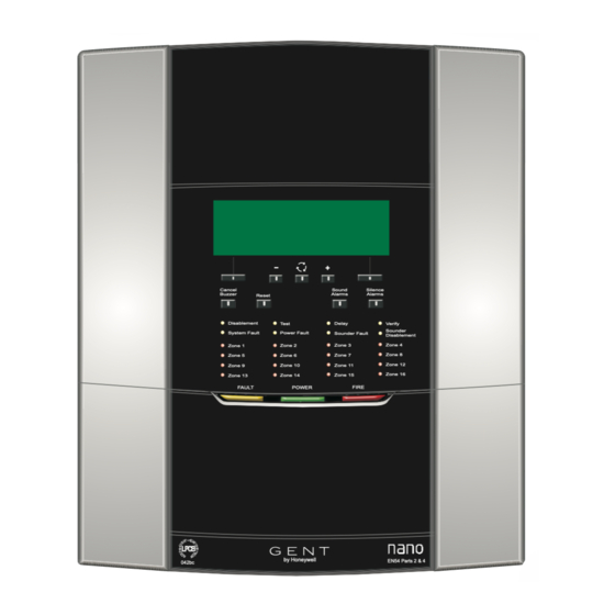
Nano panel - based
Fire detection and alarm system
Cancel
Buzzer
Reset
Disablement
Test
System Fault
Power Fault
Zone 1
Zone 2
Zone 5
Zone 6
Zone 10
Zone 9
Zone 13
Zone 14
FAULT
POWER
by Honeywell
042bc
by Honeywell
Sound
Silence
Alarms
Alarms
Delay
Verify
Sounder
Sounder Fault
Disablement
Zone 3
Zone 4
Zone 7
Zone 8
Zone 11
Zone 12
Zone 16
Zone 15
FIRE
EN54 Parts 2 & 4
Advertisement
Table of Contents

Related Manuals for Honeywell GENT Nano panel-based


Summary of Contents for Honeywell GENT Nano panel-based
- Page 1 Honeywell Commissioning Instructions Nano panel - based Fire detection and alarm system Cancel Sound Silence Buzzer Alarms Alarms Reset Disablement Test Delay Verify Sounder System Fault Power Fault Sounder Fault Disablement Zone 3 Zone 4 Zone 1 Zone 2...
-
Page 2: Table Of Contents
Commissioning instructions How to conduct a 'Display Test' - - - - - - - - - - - - - - - - - - 22 Contents How to view the panel 'Firmware' - - - - - - - - - - - - - - - - - 22 How to view the 'Historic' events log - - - - - - - - - - - - - - - - 22 Preliminary information - - - - - - - - - - - - - - - - - - - - - - 5 Address allocation - - - - - - - - - - - - - - - - - - - - - - - - 23... - Page 3 Nano panel based system Difference between Nano panel at V1.3X and V2.4X - - - - - - - - 36 How to change the 'Alarm Controls' settings - - - - - - - - - - - - 58 New features - - - - - - - - - - - - - - - - - - - - - - - - - - - - - - - - 36 How to change the 'Signal' Settings - - - - - - - - - - - - - - - - 59 New functions - - - - - - - - - - - - - - - - - - - - - - - - - - - - - - - 36...
- Page 4 Commissioning instructions Preface This is the third issue of the Commissioning instructions for the fire alarm system based on the Nano panel with Main Controller at version 2.xx. " Associated documents 2531-221 Document Pack - Quick reference / Drilling template - Installation instructions - Operating instructions Once the Nano system 'Loop' is...
-
Page 5: Preliminary Information
Nano panel based system Abbreviations Preliminary information C - Common Safety information CH -channel & Dv - Device (Loop device, also called outstation) EOL - End of line 1. Do not remove or replace printed circuit boards, fuses or attempt to wire the IO or I/O - Input Output (Interface unit) control panel with the panel powered up. -
Page 6: Pre-Visit Checks
Commissioning instructions Pre-visit checks Points to remember ¨ Unattended equipment Ensure there are accurate as fitted wiring drawings available, 2 copies are required. ¨ ¨ Where equipment is to be left unattended ensure the panel cover is fitted for safety. Ensure access will be provided to the system equipment installed in the premises. -
Page 7: System Commissioning Process
Nano panel based system System commissioning process Always power-down the panel when working on the system, such as when wiring or replacing parts Initial tests and set ups – Access levels and PIN codes – Carry out a display test and ensure DISPLAY and LEDs are working. Pre visit checks –... - Page 8 Commissioning instructions From previous page PIN Codes Backup Change the user PIN codes to site specific needs and inform the Back-up the system loop address allocation data to the panel memory. new codes to the respective users. Regularly back-up the configuration data during commissioning, do this every 15 minutes to ensure changes Installed system test made to the configuration are not lost.
-
Page 9: Controls And Indications
When illuminated it indicates that a FIRE has been detected in the protected premises. Nano Fire Alarm System [red LED] Gent by Honeywell ZONE n When illuminated it indicates that a FIRE has been detected in the respective zone(s). Menu... -
Page 10: Factory Default Settings
Commissioning instructions Zones Factory default settings ¨ All Zones - in Normal mode (not in 2-detector mode nor in 2 -zone mode) ¨ The list below provides information on how the panel is configured on leaving the factory: All Zone labels are ‘Zone n’ where n signify the zone number ¨... -
Page 11: External Wiring
Nano panel based system External Wiring The following procedures assume the Nano panel is installed. ¨ Remove the Screw cover from the Outer cover to reveal the fixing screws ¨ Using the allen key open the two fixing screws ¨ Open out the bottom edge of the Outer cover and lift it up and out ¨... - Page 12 Commissioning instructions Removable EXT.EVAC. CLASS CHANGE L1 0V L2 0V Soft skin (FireTuf) Cable LOOP END 1 LOOP END 2 FIRE OUTPUT Cable gland 24V 0V Enclosure Strip outer sheath of cable at this point, COMMON FAULT RS485 30mm down from the gland.
-
Page 13: Preparation For First Power Up
Nano panel based system Preparation for first power up The mains supply cable must remain connected to the Power supply assembly, but the mains power must remain switched OFF. Sequentially connect each external circuit one at a time and test it to ensure it is working correctly. It is a good idea to first pull out those terminal blocks of the external circuits to be tested later. Start with the loop circuit and leave only Loop End-1 connected in preparation for the power up. -
Page 14: Links
Commissioning instructions Links Backbox & LCD assembly There are LETHAL VOLTAGES present on the Power assembly. Therefore it is important when working on the MCB or PSU board to completely power down the panel. The mains supply must be switched Off and the battery supply disconnected. -
Page 15: Lithium Battery
Nano panel based system A VIEW OF THE ELECTRONIC MODULE Lithium battery WARNING Removal of LCD assembly cover exposes live parts & DANGER There are LETHAL VOLTAGES present on the Power supply assembly. Therefore it is important when working on the MCB or PSU board to completely power down the panel. -
Page 16: 12V 7Ahr Batteries
Commissioning instructions 12V 7Ahr batteries WARNING Removal of cover exposes & live parts DANGER There are LETHAL VOLTAGES present on the Power supply assembly. Therefore it is important when working on the MCB or PSU board to completely power down the panel. The mains supply must be switched off and the battery supply disconnected. -
Page 17: Location Of Fuses
Nano panel based system Location of Fuses & There are LETHAL VOLTAGES present on the Power supply assembly. Therefore it is important when working on the MCB or PSU board to completely power down the panel. The mains supply must be switched off and the battery supply disconnected. Mains fuse T3.15AH250V Display Assembly... -
Page 18: Loop Circuit Connect End 1 Only
Commissioning instructions Loop circuit connect END 1 only & Check with the installer and refer to the 'as Fitted Wiring Diagram' to ensure the cable run between Previous and Next Devices, at any point on the loop circuit HAS NOT EXCEED 250m. If cable distance is exceeded then rectification action must be taken. The following diagram shows how to connect loop devices. -
Page 19: Power Up
Nano panel based system Power up Dedicated mains supply & from consumer unit ‘Disconnect Device’ Ensure the mains cable is securely connected to the mains terminal block on the Power supply assembly and then switch On the mains power. 5A Unswitched fused spur unit "... -
Page 20: How To Adjust The Lcd Contrast
Commissioning instructions How to adjust the LCD Contrast You may need to adjust the LCD display contrast to suit the lighting level where the panel is installed. HMI assembly To decrease the contrast turn the tool anticlockwise Panel is shown without the front trimmer tool cover fitted... -
Page 21: How To Change The User Pin Code (Password Or Usercode)
Nano panel based system How to change the user PIN code (Password or Usercode) You will need to be at the appropriate Access level 3 or 4 to be able to change the Access level PIN codes. Access level 1 has no PIN code assigned. Factory default PINs are: ¨... -
Page 22: How To Conduct A 'Display Test
Commissioning instructions How to conduct a 'Display Test' It is possible to check if all the LEDS and the display of the panel have not failed by conducting a display test. You will need to be at Access Level 2 or above to conduct a Display test. Test duration is approximately 8 seconds. -
Page 23: Address Allocation
Zone 13 Zone 14 Zone 15 FAULT POWER FIRE Allocation faults by Honeywell 042bc EN54 Parts 2 & 4 PANEL ¨ The device with a hardware fault may have its LED lit. ¨ An allocation fault that has been rectified will not be recognised until after How addresses are allocated to devices re-allocation of the loop. -
Page 24: How To Manually 'Power-Down' Or 'Power-Up' The Loop
Commissioning instructions How to manually 'Power-down' or 'Power-up' the loop When working on the loop circuit or after changes have been made to the devices on the loop it is important to reallocate addresses given to devices on the loop. To re-allocate addresses to devices on the loop circuit you will need to 'Power-down' the loop and then Power-up the loop. -
Page 25: How To View The 'Loop Status
Nano panel based system How to view the 'Loop Status' The loop status provides information on the current status of the loop, total number of devices found on the loop, wiring status and the address of the last device on the loop. You will need to be at Access level 2 or above to view loop status. -
Page 26: How To 'Find Devices' On The Loop Circuit
Commissioning instructions How to 'Find Devices' on the Loop circuit To check the physical location of devices on the loop circuit you will need two people in communication with each other. While one person walks around the site and marks off the devices found on a copy of the as fitted wiring drawings, the other person operates the panel controls. -
Page 27: How To 'Print' The Loop Map
Nano panel based system Visual and audible indication of 'Find Device' Sensors and MCP ¨ A S-Quad fire sensor or manual call point will operate its LED for 0.5 second On and 0.5 second Off repeated. Sounders and S Cubed ¨... -
Page 28: How To 'Back-Up' Site Data To Flash Memory
Commissioning instructions How to 'Back-up' site data to Flash memory Once the panel has allocated addresses to all the loop devices and the loop has started you will need to back-up the site data to the Flash memory at the panel. Any subsequent changes to the configuration and labels during commissioning will also need to be backed-up. -
Page 29: How To View 'Diagnostics' Data
Nano panel based system How to view 'Diagnostics' data The diagnostic data of mains, battery, loop, 24V supply, master alarm circuits, class change, external evacuate, earth and repeat indicator can be displayed for engineering use. This information is for engineering use only and the illustration below show typical values. You will need to be at Access level 4 to view diagnostics data. Battery supply Battery load test Charger Nominal... -
Page 30: Measuring The Loop Cable Resistance And Capacitance
Commissioning instructions Measuring the loop cable resistance and capacitance Power-down and disconnect both ends of the loop wiring by pulling out the associated terminal blocks at the control panel. Resistance measurement ¨ Using a multimeter measure the resistance between the loop L1 0V (End 1) and loop L2 0V (End 2). In practice this should not be greater than 13 ohms. Capacitance measurement ¨... -
Page 31: Loop 'Short Circuit' Test
Nano panel based system Loop 'Short Circuit' test Loop 'Ground Break' test A loop short circuit isolation test should be carried out at this stage. It is recommended that the A ground break test should be carried out at this stage. A single 0V line break should not cause the sounders are switched On before conducting this test. -
Page 32: Loop 'Positive Line' Break Test
Commissioning instructions Loop 'Positive line' break test Loop 'Earth fault' tests A positive line break test should be carried out at this stage. A single +ve line break should not Earth fault tests should be carried at this stage: cause the loss of any part of the system. If the test is unsuccessful then after the rectification work is complete, re-allocate the loop circuit by using the 'Power-Down' and 'Power-Up' functions followed by 'Start Detection'. -
Page 33: To 'Save Loop Map' And Make 'Safe' Device Addresses
Nano panel based system To 'Save loop map' and make 'SAFE' device addresses The Soft addresses given to devices on the loop can be locked and saved in the non volatile memory (made SAFE) within each device and carried with the device. You will need to be at access level 4 to SAFE address devices on the loop. -
Page 34: Insertion Of New Devices On A 'Saved' Loop Map
Commissioning instructions Insertion of new devices on a 'Saved' loop map It is important to note the addresses given to new devices that are inserted on an existing ‘Saved’ loop map with loop map may not be sequential, see 1 device removed and ‘Saved’... -
Page 35: Difference Between Nano Panel At V1.00 And V1.3X
Nano panel based system Difference between Nano panel at V1.00 and V1.3x The differences between Nano panel with Main Controller at V1.00 and V1.3x are such that V1.3x covers the requirements of EN54 Part 2. Zoning devices A Nano panel having Main Controller at V1.3x will have all the detection devices in zones, with all other devices not zoned. For example: The following devices can be placed in a Zone: The following devices cannot be zoned. -
Page 36: Difference Between Nano Panel At V1.3X And V2.4X
Commissioning instructions Difference between Nano panel at V1.3x and V2.xx New features ¨ Calendar Mode supports 7 day Day/Night switching feature, see page 47. ¨ Proprietary Logo support, you can customise the logo to a site specific one using this feature, see page 69. ¨... -
Page 37: How To View Or Change 'Device Configuration
Nano panel based system How to view or change 'Device configuration' & The Nano panel recognises the 34420 Interface Unit as having 1-Output channel only. The ‘confirmation Input’ channel of this interface unit is not recognised nor used when this unit is connected to the Nano loop circuit. Two methods are shown for making changes to device configuration. -
Page 38: Typical Device Forms
Commissioning instructions Typical device forms Tee-Breaker Optical Heat Sensor and Strobe Optical Heat Sensor Strobe Optical Heat Sensor 16:15 Tue 16/02/10 16:17 Tue 09/03/10 10:18 Tue 16/02/10 16:19 Tue 09/03/10 Device:[ 2] Settings Find:[OFF] Device:[ 37] Settings Find:[OFF] Device :[ 4] Settings Find:[OFF] Device: [... -
Page 39: Typical Device Forms Continued
Nano panel based system Typical device forms continued Dual Optical Heat Sensor + CO Dual Optical Heat Sensor + CO Strobe / Speech Beam Receiver Beam Transmitter 16:32 Tue 09/03/10 16:33 Tue 09/03/10 16:34 Tue 16/02/10 16:35 Tue 16/02/10 Device:[ 21] Settings Find [OFF] Device:[... -
Page 40: Sensor States
Commissioning instructions Sensor States The state in which the Fire sensors operate can be changed from the default factory set state to another state during commissioning. The environment in which the S-Quad device is installed will determine what state is applicable. # - Default state ~ EN54 : Part 7 :2000 * EN54 : Part 5 :2002 LPCB approved sensor STATE * Meets EN54 : Part 7 :2000 Device... -
Page 41: S-Quad Heat Sensor States
Nano panel based system S-Quad Heat sensor states # - factory default state Sensitivity State Definition / Class Application in / Suitable for: a-high- to-e-none State 0# Class A1 heat Area having high levels of smoke, dust or steam State 13 Class A2 heat Area where there is moderate temperature changes plus dust, smoke or steam present State 5 High temperature Class B heat... -
Page 42: S-Quad Dual Optical Heat Co Sensor States
Commissioning instructions S-Quad Dual Optical Heat CO sensor states Sensitivity State Definition / Class Application in / Suitable for: a-high- to-h-none State 1 High sensitivity optical, Class A1 heat, Clean area or environment where early detection is required with false alarm reduction high sensitivity gas State 4 Medium sensitivity optical with no spike... -
Page 43: Beam Sensor States
Nano panel based system Beam sensor states Beam sensor States Ideal range minimum to maximum 4 or 5 2m - 30m 2 or 3 5m to 100m 0 or 1 12m tp 100m LPCB approval The Beam sensor STATES 0, 1, 2 and 3 are undergoing approval test at LPCB. -
Page 44: How To Set 'Zone' Label, Mode And Link To Another Zone
Commissioning instructions How to set 'Zone' label, mode and link to another zone You will need to be at access level 3 or above to set zone label, mode and link. Menu Select a ‘Zone’ from a range 1 to 16 Save 10:15 Tue 16/02/10 Zone:[ 1] Basic Settings... -
Page 45: How 'Cause And Effect' Interact With 'Day And Night Modes
Nano panel based system How 'Cause and Effect' interact with 'Day and Night Modes' This page illustrates the immediate and delayed Cause and Effect interaction with Day and Night modes. ¨ The immediate actions of a zone will always occur immediately in the event of a fire from the zone regardless of Day/Night mode status. ¨... -
Page 46: How To Setup Zone For 'Immediate Cause And Effect
Commissioning instructions How to setup zone for 'Immediate Cause and Effect' Using this form you can assign immediate zone action on sectors, master alarms and fire relay. You will need to be at access level 3 or above to setup immediate cause and effect. After making changes to this form you will need to back-up the data to memory. -
Page 47: How To Set Up 'Day Mode' Delays And Timeout
Nano panel based system How to set up 'Day mode' delays and timeout Using this form you can set up the Day mode delays to include initial delay, day mode delay and day mode timeout duration. You will need to be at access level 3 or above to set-up Day mode settings. The Initial delay can be up to 9 minutes and 59 seconds (Factory default setting is 30 seconds) Menu... -
Page 48: How To Manually Control Day Mode Operation
Commissioning instructions How to manually control 'Day' mode operation You can manually control Day mode to operation. You will need to be at access level 2 or above to manually switch to Day, Night or preset mode. Controls for Day mode configured for MANUAL operation 10:15 Tue 16/02/10 WARNING ! This will set the panel for DAY mode operation. -
Page 49: How To Set-Up 4-Channel Interface Devices On The Loop
Nano panel based system How to set-up 4-channel interface devices on the loop You can configure any 4-channel interface devices on the loop. You will need to be at Access level 3 or above to setup a 4-channel interface device on the loop. This form allows you to set-up the channel label, mode and assignment to zone and sector. -
Page 50: How To View Or Print Device 'Time Averages
Commissioning instructions How to view or print device 'Time averages' " Ensure all the dust covers have been removed from every sensor heads and the system is allowed to operate for at least 24 hours to obtain accurate time average and condition code readings. -
Page 51: Time Averages Explained
Nano panel based system Time averages explained The time averages provide sensor performance data with the display showing the latest time average value, foreground (fast) time average values T1 to T5 and background (slow) time average values T6 to T11. These values are used by the panel to make fire detection decision. Foreground (fast) time average Background (slow) time average readings readings... -
Page 52: How To View Sensor 'Condition Codes
Commissioning instructions How to view Sensor 'Condition Codes' The condition codes provide information about a sensor device. A code indicates small changes in the environmental condition, sensor mechanism and how the sensor performs in the system. You will need to be at access level 4 to view sensor condition codes. An * after the device number signify the device has a Condition Code 10:15 Tue 16/02/10... - Page 53 Nano panel based system " A sensor having a code 3 is automatically disabled by the system to prevent false alarms. Condition codes Meaning Action positions 0 1 2 3 4 5 6 7 8 9 1 0 0 0 0 0 0 0 0 0 or This is the sub-fire band and if set should be No action need be taken.
-
Page 54: Condition Codes For S-Quad Sensors
Commissioning instructions Condition Codes for S-Quad Sensors Condition codes Normal Sub fault band Fault band Pos. band type Description Optical subfire None Small signal sensed Subfire [Check location, state & type] [Check location, state & type] Heat subfire None Small signal sensed Subfire [Check location, state &... -
Page 55: How To Set Up An 'External Evacuate Input
EXT.EVAC. Manually silencing the system while the external evacuate input is active will cause a fault to be raised until the input is cleared. 12:30 Tue 16/02/10 Nano Fire Alarm System Gent by Honeywell [MENU] Cancel Sound Silence Buzzer Reset... -
Page 56: How To Set-Up The 'Class Change Input
To stop the class change alarms 2 - 10K Ohms - resistors must be simply release the switch. fitted as shown. CLASS CHANGE ALARM CLASS CHANGE 12:30 Tue 16/02/10 Nano Fire Alarm System Gent by Honeywell [MENU] Cancel Sound Silence Buzzer Reset Alarms Alarms... -
Page 57: How To Set Up Rs-232 And Rs-485 Serial And Usb Ports
Nano panel based system How to set up RS-232 and RS-485 serial and USB ports The RS232 port is used to connect an external printer to the control panel for printing active events and loop map. The RS485 port allows up to 4 repeat indicator panels to be connected to the control panel for repeat indication and messages of system events. -
Page 58: How To Change Access Levels Of 'Buzzer' & 'Device Disablement
Commissioning instructions How to change access levels of 'Buzzer' & 'Device Disablement' By default the buzzer can be cancelled at access level 2 and devices plus interface channels can be disabled at access level 3. It is possible to change the access levels of these controls, however you will need to be at access levels 3 or above to make these changes. -
Page 59: How To Change The 'Signal' Settings
Nano panel based system How to change the 'Signal' Settings The tone style and Interface output pulse settings of Evacuate, Alert and Class Change signals can be changed from factory default settings. You will need to be at access level 3 or above to make changes to signal settings. -
Page 60: How To Start Or Stop A 'Weekly Test
Commissioning instructions How to start or stop a 'Weekly test' On starting a weekly fire test function the system enters the zone test mode and identifies the next device to be tested. You will need to be at access level 2 or above to stop or start weekly test. 10:15 Tue 16/02/10 Stop Weekly Fire Test Warning! -
Page 61: How To 'Enable' Or 'Disable' A Zone
Nano panel based system How to 'Enable' or 'Disable' a Zone You can manually disable a zone to prevent system going into a fire condition in the event of a fire being detected in the zone. ~You can reenable the disabled zone at anytime. You will need to be at Access level 2 or above Menu Select a ‘Zone’... -
Page 62: How To Place The System In 'Commissioning Mode
Commissioning instructions How to place the system in 'Commissioning mode' You can place all the zones of the system in test state by entering the Commissioning mode, which causes all the zones of the system to enter test state. Notice the common fire light will remain lit until you exit the Commissioning mode. -
Page 63: How To Enable/Disable Master Alarms, Fire Relay And Evac. Input
Nano panel based system How to enable/disable Master alarms, Fire relay and Evac. input You can manually enable or disable the master alarms, fire relay and evacuate input. You can also view the current state of master alarms, fire relay and evacuate input. You will need to be at access level 2 or above to enable or disable these functions. -
Page 64: How To Set Up 'Maintenance Visit Reminder
Commissioning instructions How to set up 'Maintenance visit reminder' The maintenance visit reminder will appear on the display to remind responsible person(s) to arrange for the system to be maintained by the servicing organisation. The message is displayed at the beginning of the reminder day and is automatically removed after 7 days. -
Page 65: How To Return All 'Labels' To Factory Default Settings
Nano panel based system How to return all 'Labels' to factory default settings It is possible to reset all the labels entered back to factory default settings. You will need to be at access level 4 to reset labels. Menu 16:15 Tue 16/02/10 WARNING! - This will reset all labels to their factory default settings! -
Page 66: How To Return All 'Access Level Pin Codes' To Factory Settings
Commissioning instructions How to return all 'Access level PIN codes' to factory settings The Access levels 2, 3 and 4 PIN codes are reset to factory default settings. You will need to be at access level 4 to reset all PIN codes. Factory default settings: Access level 2 code: 0 0 0 0 (Customer Mode) Access level 3 code: 3 3 3 3 (Engineering Mode) -
Page 67: How To Access The Sd Card Slot On Main Control Board
Nano panel based system How to access the SD card slot on Main Control Board The SD card slot is located on the Main Control card inside the panel enclosure. A VIEW OF THE ELECTRONIC MODULE You will need to remove the battery located on the right hand side in the enclosure to gain access to the SD card slot. -
Page 68: How To Back Up All System Configuration And Labels To A Sd Card
Commissioning instructions How to back up all system configuration and labels to a SD card The system configuration data and labels can be backed up to a SD card. You will need to be at access level 4 to perform this back up. Menu 16:15 Tue 16/02/10 This will overwrite the configuration... -
Page 69: How To Restore 'Config', 'Labels' Or 'Logo' From A Sd Card
Nano panel based system How to restore 'Config', 'Labels' or 'Logo' from a SD card A previously saved system configuration data, labels and proprietary Logo file on a SD card can be restored to the panel. You will need to be at access level 4 to load configuration stored on a SD card. 16:15 Tue 16/02/10 This will load the logo data from the SD card!! -
Page 70: Tests On Installed Equipment
Commissioning instructions S-Quad Sensors Tests on installed equipment ¨ Each S-Quad should be tested for correct operation in the event of fire. Preparation ¨ The Sound and Speech part of the S-Quad should be checked to ensure each device outputs the correct signal at the appropriate volume level and ensure the strobe ¨... - Page 71 Nano panel based system Interface Units Keyswitches Interface & ¨ The keyswitch interface should be configured for correct operation and tested as per project specification. ¨ Check on operating the keyswitch the adjacent LED is lit. 1. In some instances it may not be possible to functionally test input / output circuits off an interface unit, such as when it is connected to plant equipment.
-
Page 72: Appendix A - Message Action List
Commissioning instructions Appendix A - Message Action List There are some fault events that are not self clearing and will require manual intervention. Latching fault events The following faults are identified as latching events. ¨ Slave devices lost (associated with Tee breaker) ¨... - Page 73 Nano panel based system Message meaning..possible action The panel 12V 7Ahr batteries are discharged. Check the wiring Batteries Disconnected Charger Fault Charger circuit has failed. Replace the PSU. There is an open circuit fault on the class change circuit. Check the class change circuit wiring and remove the Class Change input O/C open circuit fault.
- Page 74 Commissioning instructions Message meaning..possible action There is a fault with the sounder hardware on the S-Cube or Replace the device Device sounder failed S-Quad device. There is a hardware fault possibly associated with the voice Replace the device Device speech failed chip on the speech S-Cube or S-Quad There is a fault with the strobe hardware on the S-Cube or Replace the device...
- Page 75 Nano panel based system Message meaning..possible action There is an open circuit fault on the master alarm circuit 1. Check the wiring and ensure the end of line unit is fitted Master alarm 1 open circuit to the circuit. There is a short circuit fault on the master alarm circuit 1.
- Page 76 Commissioning instructions Message meaning..possible action There is a hardware fault possibly associated with the voice Replace the device Speech circuit has failed chip on the speech S-Cube or S-Quad The strobe circuit on the S-Quad or S-Cube device has Replace the device Strobe circuit has failed failed.
-
Page 77: Appendix B - General Guidelines
Nano panel based system Day Mode delays Appendix B - General Guidelines ¨ a Day Mode delay can be: Labels • switched ON / OFF manually at the panel ¨ • or preconfigured to operate ON, OFF or with CALENDAR Labels are given to identify location of areas on a site. -
Page 78: Appendix C - Old Beam Sensor
Nano panel based system Appendix C - old Beam sensor FOR INSTRUCTIONS ON THE S4 BEAM SENSOR PAIR AND BRACKETS SEE INSTRUCTIONS SUPPLIED WITH THE PRODUCTS. Parallel bracket assembly Steps to †. Fixed Plate Fixing nuts Bracket fixing screws Gasket cover plate Pivot for... - Page 79 Commissioning instructions Using the adjuster on the bracket, roughly align one head to face the other head. To do this: • slacken the locknuts to unscrew the Y- adjusters • to make a large adjustment remove the centre pin of the Y pivot •...
- Page 80 Nano panel based system At any time you can cancel Beam Alignment Menu Select Select Engineering Loop > Select Select Select Cancel Align Beams > Note the LEDS on the heads will flash once every 2 seconds: • a 1.9 seconds LED flash will be seen for a large signal •...
- Page 81 Commissioning instructions Appendix D - old Mains powered interface unit FOR INSTRUCTIONS ON THE NEW MAINS INTERFACE REFER TO THE LEAFLET SUPPLIED WITH THE PRODUCT. SECTOR ZONE Ratings OUTPUT INPUT OUTPUT / INPUT / Zone 24V nominal 2mA Link Position Meaning SECTOR ZONE...
-
Page 82: Appendix D - Old Mains Powered Interface Unit
Nano panel based system Dual-in-line switches IO Line tests ¨ ¨ Decide on the switch settings required for DIL switches S1 to S4. The switches Test the IO line as per project specification. The tests should be based on the type of can be set for input, output or not used (off) position. -
Page 83: Index
Commissioning instructions Index Fuses ......17 3V lithium battery ..... . . 15 SAFE . - Page 84 Nano panel based system Notes 4188-949 issue 3_05/10_Nano Comms inst.
-
Page 85: Quick Reference Menu Map
Do not burn. Gent by Honeywell reserves the right to revise this publication from time to time and make changes to the content hereof without obligation to notify any person of such revisions of changes. Hamilton Industrial Park, Waterside Road, Leicester LE5 1TN, UK...
Need help?
Do you have a question about the GENT Nano panel-based and is the answer not in the manual?
Questions and answers