
Subscribe to Our Youtube Channel
Related Manuals for H3C SecPath V100-E


Summary of Contents for H3C SecPath V100-E
- Page 1 H3C SecPath V100-E Security Gateway Installation Manual Hangzhou H3C Technologies Co., Ltd. http://www.h3c.com Manual Version: APW100-20090518...
- Page 2 SecPro, SecPoint, SecEngine, SecPath, Comware, Secware, Storware, NQA, VVG, V G, V G, PSPT, XGbus, N-Bus, TiGem, InnoVision and HUASAN are trademarks of Hangzhou H3C Technologies Co., Ltd. All other trademarks that may be mentioned in this manual are the property of their respective owners.
-
Page 3: Ethernet Cable
About This Manual Organization H3C SecPath V100-E Security Gateway Installation Manual is organized as follows: Chapter Contents Introduces the features and applications of the 1 Product Overview V100-E and provides the appearance and system specifications of the V100-E. Introduces the environment requirements for... - Page 4 Means reader be careful. Improper operation may cause data loss or damage to equipment. Means a complementary description. Related Documentation In addition to this manual, each H3C SecPath Series Security Products documentation set includes the following: Manual Description It introduces the functional features, principles...
- Page 5 H3C SecPath SSL VPN system. Obtaining Documentation You can access the most up-to-date H3C product documentation on the World Wide Web at this URL: http://www.h3c.com. The following are the columns from which you can obtain different categories of product documentation: [Products &...
-
Page 6: Table Of Contents
Table of Contents 1 Product Overview ······································································································································1-1 Overview ·················································································································································1-1 Hardware Features ·································································································································1-2 Appearance ·····································································································································1-2 System Specifications ·····················································································································1-2 LEDs ················································································································································1-3 Fixed Interface Attributes ················································································································1-3 MIMs ················································································································································1-4 2 Installation Preparations···························································································································2-1 Environment Requirements ····················································································································2-1 Temperature and Humidity··············································································································2-1 Cleanness Requirements ················································································································2-1 Electrostatic Discharge Prevention ·································································································2-2 Electromagnetic Interference Prevention ························································································2-2 Lightning Protection·························································································································2-2 Rack-Mounting Requirements·········································································································2-3... - Page 7 5 Maintaining Software·································································································································5-1 Boot Menu···············································································································································5-1 Upgrading Application and Boot ROM Using XMODEM ········································································5-2 Backing Up and Restoring the Extended Segment of the Boot ROM ····················································5-5 Upgrading the Application Program Using TFTP····················································································5-5 Uploading/Downloading Applications/Files Using FTP···········································································5-7 Modifying Boot ROM Password ············································································································5-10 Resetting a Lost Password ···················································································································5-12 6 Maintaining Hardware ·······························································································································6-1 Preparing Tools·······································································································································6-1...
-
Page 8: Leds ················································································································································1
Panel and Interface LEDs ·············································································································8-13 Troubleshooting the HNDE Module·······························································································8-14... -
Page 9: Product Overview
Product Overview Overview The H3C SecPath V100-E Security Gateway (referred to as the V100-E hereinafter) is a new-generation network security device intended for enterprise users. The V100-E serves as the access gateway for small- and medium-sized enterprises by providing various VPN access solutions, including the SSL VPN. -
Page 10: Hardware Features
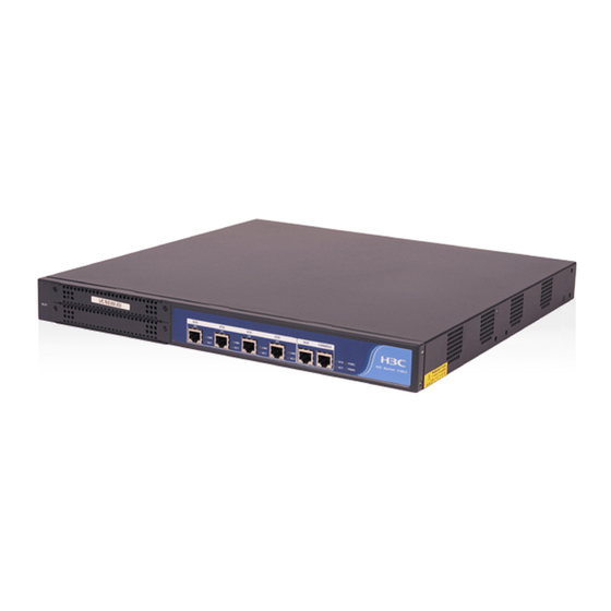
Hardware Features Appearance Figure 1-1 Front panel of the V100-E Figure 1-2 Rear panel of the V100-E System Specifications Table 1-1 Technical specifications of the V100-E Item Description MIM slot 4 × 10/100 Mbps Ethernet interfaces Fixed interface 1 AUX port (AUX) 1 console port (CONSOLE) Boot ROM 512 KB... -
Page 11: Leds
Double data rate synchronous dynamic random access memory (DDR SDRAM) stores the data exchanged between the system and the CPU. Flash memory functions as the major file storage medium to store application files, anomaly information, and configuration files. Boot ROM stores the boot file for device startup. LEDs Table 1-2 LEDs on the V100-E Description... -
Page 12: Mims
AUX port (AUX) Table 1-4 Attributes of the AUX port Item Description Connector RJ-45 Interface standard RS-232 Baud rate 1,200 bps to 115,200 bps Modem dialup Services Backup Ethernet interfaces The V100-E provides four fixed 10/100 Mbps autosensing Ethernet interfaces. Their attributes are described in Table 1-5. -
Page 13: Installation Preparations
Installation Preparations Environment Requirements The H3C SecPath series security gateways are designed for indoor application. To guarantee the normal operation and prolong the service life of the device, the installation site must meet the requirements mentioned hereunder. Temperature and Humidity The temperature and humidity in the equipment room shall be maintained at an appropriate level. -
Page 14: Electrostatic Discharge Prevention
Besides, the amounts of salt, acid, and sulfide in the equipment room should be strictly restricted. Harmful gases could accelerate the corrosion of metal parts and the aging of some parts. Table 2-3 lists the concentration limit of SO S, NH , and CI in the equipment room. -
Page 15: Rack-Mounting Requirements
Ensure the PGND cable of the chassis is well grounded. Ensure the grounding terminal of the AC power socket is well grounded. Install a lightning arrester at the input end of the power supply to enhance the lightning protection capability of the power supply. Rack-Mounting Requirements When installing the V100-E, Reserve adequate clearance around the air inlet and exhaust of the chassis for heat ventilation. - Page 16 Cables Grounding wire and power cord Console cable Optional cables Meters and other equipment Hub or LAN switch Console terminal (or a PC) Accessories for the ordered interface modules Multimeter The device is not shipped with any installation tools, meters, or equipment. You need to prepare them yourself.
-
Page 17: Installing The V100
Installing the V100-E Preparations Before installing the V100-E, make sure that you have read through Chapter 2 Installation Preparations. Make sure all the requirements mentioned in Chapter 2 are satisfied. Installation Flowchart Figure 3-1 Installation flowchart for the V100-E Start Install the cabinet (optional ) Install the device to the specified position... -
Page 18: Installing The V100
Model Physical dimensions (H × W × D) 44 × 436 × 430 mm (1.73 × 17.17 × 16.93 in.) H3C SecPath V100-E security gateway (excluding rubber feet) Follow these steps to rack-mount the V100-E: Step1 Check the grounding and stability of the rack. Use the screws to fix the mounting brackets at both sides near the front panel of the device. -
Page 19: Connecting The Pgnd Cable
Connecting the PGND Cable A correct connection of the protection ground (PGND) cable on the device chassis is an essential safeguard against lightning strokes and electromagnetic interference (EMI). When installing or using the device, make sure the PGND cable is correctly connected. The V100-E provides a grounding screw, which must be well grounded, so as to safely conduct the inductive and leaky current to the earth ground, and thereby improve the capability of the whole device to guard against the electromagnetic interference. -
Page 20: Connecting To The Console Terminal
Connecting to the Console Terminal Console port The H3C SecPath series security gateways provide an RS-232 asynchronous serial console port (CON), through which you can configure the device. For the attributes of the console port, refer to Console port (CONSOLE). -
Page 21: Connecting The Power Cable
Figure 3-5 Ethernet cable assembly When preparing network cables, it is recommended to use shielded cables for the sake of electromagnetic compatibility. Connecting the Ethernet cable Take the fixed 10/100M interface Ethernet 0/0 on the front panel of the V100-E for example. Follow these steps to connect its Ethernet cable: Read the symbol above the interface carefully to avoid misconnection. -
Page 22: Verifying Installation
Figure 3-6 Physical view of the power sockets and switches (1) PWR1 power switch (2) PWR0 power switch (3) PWR1 power socket (4) PWR0 power socket Recommended AC power socket You are recommended to use a single-phase three-terminal socket with an earth contact, which must be properly grounded. - Page 23 It is very important to verify the installation because instability and poor grounding of the V100-E and an unmatched power supply will affect the operation of the V100-E.
-
Page 24: Starting And Configuring The V100
Starting and Configuring the V100-E Booting For the initial use of the V100-E, you can only make CLI configuration through the console port. Setting Up a Configuration Environment Connecting a console terminal to the V100-E Connect the RJ-45 connector of the console cable to the console port on the V100-E and the DB-9 connector to the serial interface on the PC (see Figure 4-1). - Page 25 Step2 Define terminal parameters (using the HyperTerminal on Windows XP as an example). Select connection port Select the serial interface to be used from the Connect using drop-down list in the Connect To dialog box as shown below. Be sure to select the serial port to which the console cable is actually connected. Figure 4-3 Select a port for local configuration connection Set the connection port Set the properties of the serial port in the COM1 Properties dialog box as follows:...
-
Page 26: Powering Up The V100
Figure 4-4 Define port parameters Powering Up the V100-E Checking before power-up Check the following issues before powering up the V100-E: Both the power cord and the PGND cable are correctly connected. The voltage of the power supply matches the requirements. The console cable is correctly connected. -
Page 27: Booting Process
The console terminal display is correct. After powering up the V100-E, you can see the startup window on the console terminal (see Booting Process). After the startup (or power-on self-test), you are prompted to press Enter. When the prompt <H3C> appears, the system is ready for your configuration. -
Page 28: Configuration Fundamentals
Step4 Configure routes, and if a dynamic routing protocol is enabled, set parameters for the protocol. Step5 Configure security features as required. Step6 Configure reliability features as required. For more information on the configuration of protocols and functions for the V100-E, see the H3C SecPath Series Security Products Operation Manual. Command Line Interface Characteristics of CLI The CLI of the V100-E enables you to configure, manage, and maintain the V100-E. -
Page 29: Maintaining Software
Maintaining Software The V100-E manages three types of files: Boot ROM program files Application program files Configuration files Software maintenance mainly involves upgrading/downloading Boot ROM/application program files and uploading/downloading configuration files. Boot Menu This section introduces the Boot menu that you use in maintaining the software of the V100-E. Set up a configuration environment (see Figure 4-1) and then boot the V100-E. -
Page 30: Upgrading Application And Boot Rom Using Xmodem
If you fail to upgrade the software and the system prompts “invalid version” although you use the correct software version, you can select this option to ignore the version check during software upgrade. Note that this option works only once when you select it. The system resumes version check after you reboot the V100-E. - Page 31 Download speed is 115200 bps. Change the terminal's speed to 115200 bps, and select XModem protocol. Press ENTER key when ready. Step3 Change your terminals baud rate (see Figure 4-4) to the same baud rate for software downloading (115200 bps in this example). After that, disconnect the terminal ([Dial-in/Disconnect]), reconnect it ([Dial-in/Dialing]), and press Enter to start downloading.
- Page 32 Step6 After completing the downloading, the system begins writing data to the Flash memory and then displays the following information in the terminal window, indicating the completion of the downloading: XModem download completed, Packet length 8790321 bytes. System file length 7868992 bytes, http.zip file length 921329 bytes. Writing file flash:/system to FLASH...
-
Page 33: Backing Up And Restoring The Extended Segment Of The Boot Rom
Backing Up and Restoring the Extended Segment of the Boot ROM Backing up the extended segment to Flash memory Follow these steps to back up the Boot ROM program. Step1 Enter the Boot menu, and select 7 to enter the Boot ROM operation menu. Step2 Select 4 in the Boot ROM operation menu to copy the current extended segment of the Boot ROM program to the Flash memory. - Page 34 Start the TFTP server on the PC connected to the Ethernet interface on the V100-E and set the path to the file to be downloaded. Configure the V100-E Step1 Boot the V100-E and enter the Boot menu (refer to Boot Menu for details). Select 2 to enter the Net Port Download Menu shown as follows: Net Port Download Menu: Change Net Parameter...
-
Page 35: Uploading/Downloading Applications/Files Using Ftp
Writing into Flash Succeeds. Uploading/Downloading Applications/Files Using FTP The H3C SecPath series security gateway offers FTP server function, which provides you another way of updating configuration files, and upgrading application and Boot ROM program. You only need to connect a FTP client, local or remote, to the V100-E. When you pass the authentication, you can upload and download configuration files or applications. - Page 36 Step1 Configure the authentication mode. You can perform AAA authentication configuration as needed. See the AAA and RADIUS configuration part in the H3C SecPath Series Security Products Operation Manual for details. Step2 Add the username and password. [VPNGateway] local-user VPNGateway VPNGateway is the username.
- Page 37 Step5 Add an authority level. [VPNGateway-luser-vpngateway] level 3 Step6 Enable the FTP server. [VPNGateway] ftp-server enable After the above operation, the FTP server is enabled on the V100-E, and a user is set. Then, any FTP client program can access FTP server using this user name and password. Uploading/downloading application, configuration files and uploading Boot ROM program Step1 Enter the path of the files or applications in DOS window, perform FTP command, and create the FTP connection to the V100-E, for example:...
-
Page 38: Modifying Boot Rom Password
When using FTP to upgrade the application program, make sure that the V100-E has enough flash memory. If the memory is not enough, you need to use the delete /unreserved command to permanently delete old version files or other files to save the memory space; otherwise, new files cannot be uploaded. - Page 39 To enter the Boot menu, you must press Ctrl + D within three seconds after the “System starts booting” prompt appears on the configuration terminal; otherwise, the system starts decompressing the program. You need to restart the V100-E if you want to enter the Loader menu after entering the Boot ROM extended segment.
-
Page 40: Resetting A Lost Password
Resetting a Lost Password Please contact support technicians if your Boot ROM password or user password of the V100-E is lost. Then you can get assistance to log in to the V100-E again and set a new password. 5-12... -
Page 41: Maintaining Hardware
Maintaining Hardware Preparing Tools Phillips screwdrivers Flat-blade screwdrivers ESD-preventive wrist straps Antistatic bags None of the above installation tools are shipped with the device. Opening the Chassis Cover Follow these steps to open the chassis cover of the V100-E: Step1 Power off the device and unplug the power cord. Step2 Unplug all interface cables from the front panel while keeping the ground cable connected. -
Page 42: Installing And Removing A Ddr Sdram
Replace the hardware of the V100-E only when necessary and under the guidance of technical engineers. Do not remove the H3C tamper-proof seal on the chassis cover of the device without permission. If you want to open the chassis, contact your sales agent for permission. Otherwise, H3C shall not be held liable for any consequence caused thereby. -
Page 43: Locating The Ddr Sdram On The Main Board
The V100-E needs to maintain a large routing table or support memory-demanding operations. Upon starting up the V100-E, the system displays: ************************************************** * H3C SecPath Series Gateway BOOTROM Version 1.27* ************************************************** Copyright(C) 2004-2007 by Hangzhou H3C Technologies Co.,Ltd. Compiled at Wed Oct 31 10:33:08 CST 2007 Testing memory...OK! -
Page 44: Removing A Ddr Sdram
Figure 6-3 Location of the DDR SDRAM on the main board Each DDR SDRAM has one positioning recess at its bottom for correct orientation. When installing a DDR SDRAM into a memory bank, press the positioning recess into the pin in the bank. Removing a DDR SDRAM Follow these steps to remove the DDR SDRAM of the V100-E: Step1 Locate the DDR SDRAM on the main board. -
Page 45: Install A Ddr Sdram
Hold the memory module only by its non-conductive edge. Because a memory module is vulnerable to ESD, improper operation may cause damage to it. Do not use too much force in the operation. Do not touch the surface-mounted components of the memory module directly with your hands. Install a DDR SDRAM Follow these steps to install a DDR SDRAM: Step1 Locate the position to install the DDR SDRAM. -
Page 46: Troubleshooting
Troubleshooting Troubleshooting PSU Symptom The power LED (PWR) is always off. Solution Check whether: The power switch of the V100-E is turned on. The site power supply is turned on. The power cord is properly connected. The required power supply is used. Do not hot-swap the power cable. -
Page 47: Troubleshooting Application Upgrading
Bits per second = 9600 Data bits = 8 Parity = none Stop bits = 1 Flow control = none Emulation = VT100 Reset them if they are not set to these values. Troubleshooting Application Upgrading Fault 1 Symptom Boot the V100-E, upgrade Comware software using TFTP, and the system displays the following: Net Port Download Menu: Change Net Parameter Download From Net... - Page 48 The downloaded files are not available. The paths of the files are not correct. Confirm that the files to be downloaded are under the path specified by the TFTP server. Fault 3 Symptom Boot the V100-E, upgrade Comware software using TFTP, and the system displays the following: Net Port Download Menu: Change Net Parameter Download From Net...
-
Page 49: Mim Modules
MIM Modules MIM Options Currently the V100-E supports these types of MIMs: 1-port 10Base-T/100Base-TX FE interface module (1FE) 2-port 10Base-T/100Base-TX FE interface module (2FE) 4-port 10Base-T/100Base-TX FE interface module (4FE) 1-port 10Base-T/100Base-TX/1000Base-T Ethernet interface module (1GBE) 2-port 10Base-T/100Base-TX/1000Base-T Ethernet interface module (2GBE) 1-port 1000Base-LX/1000Base-SX Ethernet interface module (1GEF) 2-port 1000Base-LX/1000Base-SX Ethernet interface module (2GEF) High-performance network data encryption module (HNDE) - Page 50 Step3 Select a slot and push the MIM into the chassis until it is fully seated in the slot and its front panel is flush with the front of the chassis. Step4 Tighten the captive screws to secure the MIM. Step5 Power up the V100-E and check the state of the ACT LED for the slot on the V100-E.
-
Page 51: Troubleshooting An Mim
Troubleshooting an MIM You can read the LEDs on the MIM panel to check for the MIM installation. If the MIM on the V100-E does not operate normally, check that: Correct interface cables are used. The interfaces are working well by reading the interface LEDs. The configurations on the MIM are validated by executing the display command. -
Page 52: Interface Attributes
Figure 8-4 2FE module Appearance of the 4FE module Figure 8-5 shows the 4FE module. Figure 8-5 4FE module Interface Attributes Table 8-1 shows the interface attributes of the 1FE, 2FE and 4FE modules. Table 8-1 Interface attributes of the 1FE, 2FE and 4FE modules Attribute 1FE module 2FE module... -
Page 53: Panel And Interface Leds
Panel and Interface LEDs Figure 8-6 shows the 1FE module panel. Figure 8-6 1FE module panel 10/100BASE-TX Figure 8-7 shows the 2FE module panel. Figure 8-7 2FE module panel Figure 8-8 shows the 2FE module panel. Figure 8-8 4FE module panel Table 8-2 describes the LEDs on the 1FE/2FE/4FE module panel and how to read their state. - Page 54 Making an Ethernet cable To make an Ethernet cable with RJ-45 connectors using a category-5 twisted-pair cable, refer to Figure 8-10. A category-5 twisted-pair cable is composed of eight wires that are identified and grouped by colors of the outer insulator. Usually a solid color wire and a white/solid color wire are organized in pairs. But sometimes, wires are also paired by color coded points.
-
Page 55: Connecting The Interface Cable
Category-5 Direction of Direction of RJ-45 twisted-pair RJ-45 signal signal cable –– White (brown) –– –– Brown –– Ethernet cables are divided into two categories: straight-through and crossover. Straight-through cable: The sequences of the twisted pairs crimped in the RJ-45 connectors at both ends are the same. -
Page 56: Appearance
Full duplex. Appearance Appearance of the 1GBE module Figure 8-11 1GBE module Appearance of the 2GBE module Figure 8-12 2GBE module Interface Attributes Table 8-5 shows the interface attributes of the 1GBE and 2GBE modules. Table 8-5 Interface attributes of the 1GBE and 2GBE modules Attribute 1GBE module 2GBE module... -
Page 57: Interface Cable
Figure 8-13 Front panel of 1GBE Figure 8-14 Front panel of 2GBE Table 8-6 describes the LEDs on 1GBE and 2GBE modules. Table 8-6 LEDs on 1GBE and 2GBE modules Description OFF means that no link is present. LINK ON means that a link is present on the interface. OFF means that no data is being transmitted or received. -
Page 58: 1Gef/2Gef Module
1GEF/2GEF Module Introduction 1GEF and 2GEF modules are 1000Base-LX/1000Base-SX Ethernet optical interface modules, where GE stands for Gigabit Ethernet and F stands for fiber. 1GEF and 2GEF can provide the communications between the V100-E and a LAN. The 1GEF and 2GEF modules support: Five types of 1000Base-LX/SX SFP optical transceivers, including short-distance multi-mode (850 nm) optical module, medium-distance single-mode (1310 nm) optical module, long-distance single-mode (1310 nm) optical module, long-distance single-mode (1550 nm) optical module, and... -
Page 59: Panel And Interface Leds
Full duplex mode Operating mode 1000 Mbps Use only the optical transceivers that have pass H3C authentication. Panel and Interface LEDs Figure 8-17 and Figure 8-18 show the front panel of 1GEF and 2GEF respectively. Figure 8-17 Front panel of 1GEF Figure 8-18 Front panel of 2GEF Table 8-8 describes the LEDs on 1GEF and 2GEF modules. -
Page 60: Interface Cable
Table 8-8 LEDs on 1GEF and 2GEF modules Description OFF means that no link is present. LINK ON means that a link is present on the interface. OFF means that no data is being transmitted or received. ON means that data is being transmitted or received. Interface Cable Ethernet cable The 1GEF and 2GEF modules need to work with 1000Base-SX/1000Base-LX SFP optical transceivers... -
Page 61: Hnde Module
Step3 Power up the V100-E and check state of the corresponding LED on the V100-E. ON means that the module has succeeded in the POST and works normally. OFF means that the module fails the POST. Contact your agent in the latter case. Step4 Check the state of the LINK LED on the GEF module. - Page 62 Troubleshooting the HNDE Module Symptom 1: The STATUS LED stays off after turning on the V100-E. Solution: The STATUS LED should stay solid on after powered on. The OFF status indicates that the HNDE module or some hardware is not powered on properly. Check the connection of the power supply.
- Page 63 Table of Contents Appendix A Regulatory Compliance Information ···················································································· A-1 Regulatory compliance standards·········································································································· A-1 European Directives compliance ··········································································································· A-1 LVD/EMC Directive························································································································· A-1 WEEE Directive–2002/96/EC········································································································· A-2 USA regulatory compliance ··················································································································· A-2 FCC Part 15···································································································································· A-2 FDA················································································································································· A-2 Canada regulatory compliance ·············································································································· A-2 ICES-003 ········································································································································...
-
Page 64: Appendix A Regulatory Compliance Information
EN 60825-1 EN 60825-2 FDA 21 CFR Subchapter J European Directives compliance LVD/EMC Directive These products comply with the European Low Voltage Directive 2006/95/EC and EMC Directive 2004/108/EC. A copy of the signed Declaration of Conformity can be downloaded from: http://www.h3c.com/portal/Technical_Documents... -
Page 65: Weee Directive-2002/96/Ec
This device must accept any interference received, including interference that may cause undesired operation. If the customer modifies the equipment without the authorization of H3C and 3Com, which directly or indirectly contribute to the equipment incompliance with FCC requirements for Class A digital devices, H3C is not liable for such interference problem and the expenses incurred therefrom shall be covered by the customers. -
Page 66: Japan Regulatory Compliance
Japan regulatory compliance VCCI These products comply with the requirements of VCCI Class A Information Technology Equipment (ITE). Warning: If this equipment is used in a domestic environment, radio disturbance may arise. When such trouble occurs, the user may be required to take corrective actions. EN55022 / CISPR 22 Compliance These products comply with the requirements of EN55022/CISPR 22 for Class A Information Technology Equipment (ITE). -
Page 67: Appendix B Safety Information Sicherheits Informationen安全信息
Appendix B Safety Information Sicherheits informationen 安全信息 Overview Überblick 概述 This section introduces part of the safety precautions that should be followed during the installation and maintenance of the equipment. And for the safety statements and warnings, there followed the translations of both German and Chinese to comply with the national requirements. -
Page 68: Conventions Used Symbole Erläuterung应用惯例
为了避免可能发生的事故, 请在进行任何操作前, 仔细阅读设备操作手册和本章节的安全规范。 手册中 出 现的说明、注意、警告、危险,不能涵盖所有的安全预防,仅仅是在整个操作过程中的安全提示和补充。 因此,负责安装和日常维护本设备的人员必须具备安全操作基本技能。 操作人员要按照当地的安全规范进行操作。出现在产品手册中的安全预防措施仅仅是当地安全规范的补 充。 在操作本设备时,请认真执行产品手册规定的安全规范。 Conventions Used Symbole Erläuterung 应用惯例 The symbols in this manual are shown in the following table. They are used to remind the reader of the safety precautions during equipment installation and maintenance. Die Symbole in diesem Handbuch verwendeten sind in der folgenden Tabelle dargestellt. - Page 69 Nehmen Sie das Gerät nicht in Betrieb, solange das optische Fenster nicht geschlossen ist. Der Laserstrahl kann zu Augenverletzungen führen. 为了避免光纤发出的高能量的激光光束伤害到视网膜,请不要直视光接口。 These products may be powered by a DC RPS, if the Customer pwer source,but the DC RPS pwer source must be supplied by H3C company...
-
Page 70: Power Cable Zuleitung电缆
DC RPS Energiequelle angetrieben werden, aber die DC RPS Energiequelle muß von H3C geliefert werden. 设备可以使用 DC RPS 电源供电,如果用户希望使用 DC RPS 电源为设备供电,那么必须向杭州华 三通信技术有限公司购买指定型号的 DC RPS 电源。 Power Cable Zuleitung 电缆 Installation and removal of live power cable is prohibited strictly. Transient contact between the core of power cable and conductor may generate electric arc or spark or electric arc, which may lead to fire or eye injury. -
Page 71: Laser Laser激光辐射
Für mit Gleichstrom betriebene Ausrüstung benutzen Sie bitte eine 1.0 mm oder 16 AWG Zuleitung. Für mit Wechselstrom betriebene Ausrüstung benutzen Sie bitte eine 1.0 mm oder 16 AWG Zuleitung. DC 电源设备,请使用 1.0mm 或 16AWG 电缆; AC 电源设备,请使用 1.0mm 或 16AWG 电缆。 Laser Laser 激光辐射...
Need help?
Do you have a question about the SecPath V100-E and is the answer not in the manual?
Questions and answers