Table of Contents
Advertisement
Quick Links
Advertisement
Table of Contents

Subscribe to Our Youtube Channel
Related Manuals for Horiba Scientific DS-72G


Summary of Contents for Horiba Scientific DS-72G
- Page 1 Instruction Manual COND METER ( DS-72G )
-
Page 3: Preface
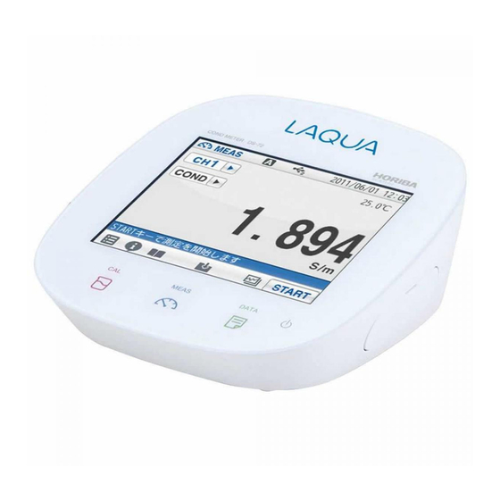
Brand (pet name): LAQUA Series name: Benchtop pH/Water Quality Analyzer Model: DS-72G Model description: COND METER Be sure to read this manual before using the product to ensure proper and safe operation of the instrument. Also safely store the manual so it is readily possible whenever necessary. - Page 4 Regulations ■ Regulations ● EU regulations ● Conformable standards This equipment conforms to the following standards: EMC: EN61326-1 Class B, Basic electromagnetic environment Safety: EN61010-1 RoHS: EN50581 9. Monitoring and control instruments Warning: This product is not intended for use in industrial environments. In an industrial environment, electromagnetic environmental effects may cause the incorrect performance of the product in which case the user may be required to take adequate measures.
- Page 5 Regulations ● Authorised representative in EU HORIBA UK Limited 2 Dalston Gardens, Stanmore, Middx HA7 1BQ, UK Regulations ● FCC rules Any changes or modifications not expressly approved by the party responsible for compliance shall void the user's authority to operate the equipment.
- Page 6 Regulations ● China regulation Meaning of Marking This marking is applied to electric and electronic products sold in the People's Republic of China. The figure at the center of the marking indicates the environmental protection use period in years. (It does not indicate a product guarantee period.) It guarantees that the product will not cause environment pollution nor serious influence on human body and property within the period of the indicated years which is counted from...
- Page 7 Regulations Name and amount of hazardous substance used in a product Hazardous substance Hexa- Poly Poly Unit name Cad- valent bromo- Lead bromo- cury mium chrom- diphenyl (Pb) biphenyl (Hg) (Cd) ether (PBB) (Cr (VI)) (PBDE) Main unit Battery AC adapter Cable Stand Printer...
-
Page 8: For Your Safety
For Your Safety ■ For Your Safety ● Hazard classification and warning symbols Warning messages are described in the following manner. Read the messages and follow the instructions carefully. ● Hazard classification This indicates an imminently hazardous situation which, if not avoided, will result in death or serious injury. - Page 9 For Your Safety ● [FRA] Informations de sécurité Veillez à lire le présent manuel avant d’utiliser le produit de manière à garantir son utilisation correcte et sûre. De même, rangez le manuel dans un lieu sûr de manière à pouvoir vous y reporter lorsque cela est nécessaire.
- Page 10 For Your Safety ● [SWE] Säkerhetsinformation Se till att du läser denna handbok innan du börjar använda produkten för en korrekt och säker användning av den. Spara sedan handboken på en säker och lättåtkomlig plats så att du kan konsultera den när så behövs.
- Page 11 For Your Safety ● [POL] Informacje dotyczące bezpieczeństwa Przed przystąpieniem do użytkowania tego produktu należy dokładnie zapoznać się z niniejszą instrukcją, aby zapewniona była prawidłowa i bezpieczna eksploatacja produktu. Instrukcję przechowywać w bez- piecznym miejscu, aby w razie potrzeby była zawsze dostępna. Treść...
- Page 12 For Your Safety ● [JPN] 安全情報 ご使用になる前に、本書を必ずお読みください。お読みになった後は 必要なときにすぐに取り出せるように大切に保管してください。 本書に記載されている内容は予告なく変更される場合があります。あ らかじめご了承ください。 ● 設置環境 本製品は、EN61326-1 で定義される工業環境で使用することを想定し た製品ではありません。 工業環境においては、電磁妨害の影響を受ける可能性があり、その場 合には使用者が適切な対策を講ずることが必要となることがありま す。 本製品は、 EN61010-1 で定義される以下の環境用に設計されています。 過電圧カテゴリー II ● 汚染度 2 ●...
- Page 13 For Your Safety ● Safety Precautions This section provides precautions to enable you to use the product safely and correctly and to prevent injury and damage. The terms of DANGER, WARNING, and CAUTION indicate the degree of imminency and hazardous situation. Read the precautions carefully as it contains important safety messages.
- Page 14 For Your Safety CAUTION Do not use the cable of serial communication, USB, or AC adapter under wet or humid conditions. Otherwise, it may cause a fire, electric shock, or breakage.
-
Page 15: Product Handling Information
Product Handling Information ■ Product Handling Information ● Operational precautions Only use the product including accessories for their intended ● purpose. Do not drop, crash, or give any physical impact on the instrument. ● Do not immerse the instrument into alcohol, organic solvent, strong ●... -
Page 16: Manual Information
Manual Information ■ Manual Information ● Description in this manual This interprets the necessary points for correct operation and notifies the important points for handling the product. This indicates the part where to refer for information. HINT! This indicates reference information. ●... -
Page 17: Table Of Contents
Contents ■ Preface ....................... I ■ Regulations ....................II ■ For Your Safety ..................VI ■ Product Handling Information ............. XIII ■ Manual Information ................XIV Chapter 1 Overview ................... 1 1.1 Description of Each Part ................ 1 1.1.1 Rear ....................1 1.1.2 Display .................... - Page 18 Contents 2.16 Resetting to Factory Defaults ............34 Chapter 3 COND (Conductivity) Measurement ........35 3.1 COND Calibration ................. 35 3.1.1 Automatic Calibration Setting ............35 3.1.2 Calibration of Standard Solution ........... 36 3.2 COND Measurement Setting ..............39 3.2.1 Cell Constant Setting ..............39 3.2.2 COND Measurement Unit Setting ..........
- Page 19 Contents 6.6 TDS Measurement ................59 Chapter 7 Application Mode ..............60 7.1 Pharmacopeia Mode ................60 7.1.1 Shift to Pharmacopeia Mode ............61 7.1.2 Measured by USP (Stage 1) ............61 7.1.3 Measured by USP (Stage 2) ............62 7.1.4 Measured by EP ................
-
Page 21: Chapter 1 Overview
Chapter 1 Overview This chapter describes functions and basic operations of the instrument. 1.1 Description of Each Part 1.1.1 Rear CH2 reference electrode CH2 measurement electrode CH2 for temperature electrode 1.1.2 Display Status bar Touch panel Icon bar POWER key CAL key DATA key MEAS key... -
Page 22: Left Side
1.1.3 Left Side Serial communication connector (RS-232C) AC adapter connector Analog output connector 2 (CH2 data) Analog output connector 3 (Alarm) 1.1.4 Right Side Connector for Connector for USB communication USB memory with a personal computer... -
Page 23: Accessories
1.1.5 Accessories Name Function AC adapter* Used to power the instrument. Electrode stand Used to move and set electrodes during measurement. Rubber cover Protects the instrument side surfaces. Instruction manual Instructs the usage of the instrument. Quick manual Instructs the operations of calibration and measurement. The AC adapter includes 6 plug adapters. -
Page 24: Identification Of Manufacturing Date
1.1.6 Identification of Manufacturing Date Manufacturing date can be identified from MFG No. described in the ID label on the backside of the instrument. Third number from the left in the MFG No. indicates manufacturing year. Forth alphabet from the left in the MFG No. indicates manufacturing month. The alphabet is assigned to month according to the table below. -
Page 25: Icons (Icon Bar)
1.1.8 Icons (Icon Bar) The icons displayed on the bottom of the touch panel allow you to set up the instrument, check calibration information, and print out and save data. Icon Function Used to perform measurement, display the Meter Menu SET screen, and switch to the inspection and application modes. -
Page 26: Status Icons
1.1.9 Status Icons The icons displayed on the top of the touch panel show information on the instrument. Status icon Function Shows that the automatic hold function is ON, and that the end point is determined automatically according to input Auto hold signals from the electrode based on the pre-selected stability criterion of measurement values. -
Page 27: Meas Screen
1.1.10 Meas Screen Status Temperature Date and time Measurement mode compensation electrode connection indicator Channel Temperature Measurement item HOLD indicator Measurement values Measurement operation Icon information Indicator Name Description Displayed: A temperature compensation electrode Temperature is connected. compensation The displayed temperature is the electrode electrode temperature (ATC). -
Page 28: Basic Operation Of Touch-Panel And Touch-Key
1.2 Basic Operation of Touch-Panel and Touch-Key The instrument has touch panel and keys and you can operate it by touching the screen. The 3 basic operations of Tap, Flick, and Drag allow you to operate the instrument intuitively. This section describes the basic operations. Operation Description Tap on the screen lightly once with a finger. -
Page 29: Function And Operation Of The Meas Screen
1.3 Function and Operation of the Meas Screen The MEAS screen has three display methods to check variation and tendency of measurement values. You can shift the screen to the digital, graph or analog screen by flicking it. Digital display If arrows, like , appear when you touch the screen, you can flick in the directions to switch the screen display. - Page 30 ● Graph display You can change the scale of the vertical axis in the graph display. It allows you to check a small change in measurement values. The vertical axis is zoomed in. The displayed range narrows. Displays the next or Displays the previous data.
-
Page 31: Assembling The Electrode Stand
1.4 Assembling the Electrode Stand Attach the stand shaft to the stand base. Stand shaft Attach the stopper and the stand arm to the stand shaft. Stand arm Stopper Stand base... -
Page 32: Connecting The Electrode
1.5 Connecting the Electrode 1.5.1 Electrode Connector CH2 reference electrode CH2 measurement electrode CH2 for temperature electrode Insert the groove of electrode connector by fitting with the connector socket pin of the instrument. Do not insert it with force when the pin and groove are misaligned. -
Page 33: Connecting The Power Source
1.6 Connecting the Power Source Insert the AC adapter cable by fitting with the connector socket of in the instrument. Do not insert the cable with force when the connectors do not match. AC adapter connector 1.7 Connecting the Printer Insert the printer cable by fitting with the connector socket of in the instrument. -
Page 34: Connecting The Personal Computer
1.8 Connecting the Personal Computer USB connector for personal computer communication ・ Use designated cables to connect with a personal computer. Designated cable Parts name: USB cable (1 m) Parts No.: 3200373941 ・ Make sure that the transfer formats of the measuring instrument and personal computer are same. -
Page 35: Turn On The Power
1.9 Turn ON the Power Press and hold the POWER key for 2 seconds or longer. Following the startup screen, the MEAS screen will be displayed. ・ The POWER key does not work for 10 seconds after the AC adapter is connected. Wait for a while after connecting AC adapter. -
Page 36: Chapter 2 Before Measurement (Meter Set)
Chapter 2 Before Measurement (Meter SET) This chapter explains the procedures of the instrument condition setting, which should be performed before measurement. 2.1 Meter SET Screen and tap Meter SET. Meter SET items are displayed. You will see the remaining items by dragging. Select items and set the conditions. -
Page 37: Custom Setting
Each HOLD condition is described below. Stability condition Function In the AUTO HOLD mode, the instrument judges potential stability Auto hold automatically to set the measurement values. Content Measuring Mode Temperature target Time (s) Criteria 【Default】 (C) COND, Resist Minimum display digit: 1 digit EXACT 0.30 ppt (0.03%) 10 mg/L... -
Page 38: Sample Name Setting
2.4 Sample Name Setting You can set sample names for CH2. on the right of the Sample name item. on the right of the item in the CH2 to enter the sample name. to switch the keyboard entry screen of Alphabet -->... -
Page 39: Interval Memory Setting
2.5 Interval Memory Setting The measured data can be stored at set time intervals. on the right of the Interval memory item and select ON. Enter Interval Time Display the Time item when select ON. on the right of the Time item. Enter the interval time in the numerical key screen. -
Page 40: Usb Memory Setting
2.6 USB Memory Setting Memory data can be written into a USB memory. on the right of the USB Memory item. The USB memory setting screen is displayed. to return to the previous screen. Simultaneously Memory When a USB memory is inserted into the instrument, the data can be written into both the instrument and USB memories at the same time. - Page 41 Format Use this item to format a USB memory in FAT16. Note that formatting deletes all stored data. on the right of the Format item and tap in the execution confirmation screen. To cancel the operation, tap A message that formatting is in progress appears during formatting.
-
Page 42: Printer Setting
2.7 Printer Setting The Printer item allows you to set printing contents, etc. effective only when a printer is connected with the instrument. on the right of the Printer item. The printer setting screen is displayed. to return to the previous screen. Printer Test When a printer is connected with the instrument, this item allows you to perform a printer test. - Page 43 ● When selecting CUSTOMIZE CUSTOMIZE allows you to select items you want to print out among Measurement date/time, User name, Settings, Sensor info•Cal. User. Select CUSTOMIZE from Printout Layout, and on the right of each printing item. is ON: The item is selected. is OFF: The item is not selected.
-
Page 44: Screen Settings
2.8 Screen Settings You can change screen settings. on the right of the Screen settings item. The screen settings screen is displayed. to return to the previous screen. Screen Theme You can select one among 4 type screen themes; STANDARD, COOL, MONOTONE and KYOTO. on the right of the Screen theme item. - Page 45 Power Saving Mode You can set the time for power saving mode. on the right of the Power saving mode item and select ON. ● Back light off time When selecting ON for Power saving mode, the Back light off time item is displayed. on the right of the Back light off time item.
-
Page 46: Sound Setting
2.9 Sound Setting You can change sound settings. on the right of the Sound settings item. The sound settings screen is displayed. to return to the previous screen. Sound Theme You can select one among 4 type sound themes; STANDARD, COOL, MONOTONE and KYOTO. on the right of the Sound theme item. -
Page 47: Language Setting
2.10 Language Setting You can change language settings. on the right of the Language item. Select the language. To cancel the operation, tap 2.11 Security Setting Security setting allows you to set a password for an administrator of the instrument. After the setting is ON, the instrument requires you to select an operator name at the startup. - Page 48 When using the Security setting, administrator registration is required. Tap the blank area at the right of "User name" to display the letter entry screen. Enter the operator name, and tap Tap the to switch the keyboard entry screen of Alphabet and Numerical/Symbol. Tap to input in lower-case alphabets.
-
Page 49: User Entry/Info Change/Delete
2.12 User Entry/Info Change/Delete When an operator is registered, the operator name can be put in measurement/calibration information, data printouts, data memory. on the right of the User entry/info change/delete item, when user registration, change password and user deletion. The User entry/info change/delete screen is dis- played. - Page 50 User Information Changing Operators can change the password. on the right of the User info change item. Enter the password, and tap Tap the current password at the right of "Pass- word" to display the numerical-key screen. Enter the password, and tap The password can be set between 2 and 10 characters.
-
Page 51: Date Setting
2.13 Date Setting You can set the date and time. on the right of the Date/Time setting item. The Date/Time setting screen is displayed. to return to the previous screen. Date You can set the date. on the right of the Year, month, day item. -
Page 52: Analog Output Adjustment
2.14 Analog Output Adjustment Voltage output can be acquired from the analog output connector located at the instrument side on the right of the Analog output adj. item. The Analog output adj. screen is displayed. to return to the previous screen. How to Analog Output Adj. -
Page 53: Temperature Sensor Calibration
2.15 Temperature Sensor Calibration You can perform calibration of the temperature sensor. on the right of the Temp. calibration item. The Temp. calibration setting screen is dis- played. To cancel the operation, tap to return to the previous screen. Display the measured temperature by the temperature sensor connected to the instrument. -
Page 54: Resetting To Factory Defaults
2.16 Resetting to Factory Defaults You can reset the instrument to the factory default conditions. on the right of the Meter initialization item. in the execution confirmation screen. , when do not resetting. Display the confirmation screen again, and tap , when do not resetting. -
Page 55: Chapter 3 Cond (Conductivity) Measurement
Chapter 3 COND (Conductivity) Measurement 3.1 COND Calibration This section describes the procedures to set the conditions of COND calibration. Set the condition of temperature compensation before COND calibration according to "3.2 COND Measurement Setting" (P.39). The cell constants of COND electrodes are different. When using the conductivity electrode for the first time, set the cell constant written on the electrode into the instrument before use according to "3.2.1 Cell Constant Setting"... -
Page 56: Calibration Of Standard Solution
3.1.2 Calibration of Standard Solution A verified cell constant is written on a COND electrode label. However, the actual cell constant may fluctuate depending on the usage circumstances and it is desirable to calibrate the cell constant in that case. The procedures of cell constant calibration are mentioned below. - Page 57 Manual calibration Tap the value next to "Set:" to display the numer- ical-key screen. Enter the conductivity value of the standard solu- tion, and then tap Select the auxiliary unit of the standard solution for calibration using , and then enter the concentration of the standard solution.
- Page 58 ● Conductivity standard values at various temperature Temp. Conductivity value at 25°C (°C) 84.00 (S/cm) 1413 (S/cm) 12.88 (mS/cm) 111.8 (mS/cm) 64.01 7.15 65.4 65.00 8.22 74.1 67.00 1020 9.33 83.2 68.00 1147 10.48 92.5 70.00 1173 10.72 94.4 71.00 1199 10.95 96.3...
-
Page 59: Cond Measurement Setting
3.2 COND Measurement Setting This section describes the procedures to set the conditions of COND measurement. Tap the channel setting and the measurement item in the MEAS screen to set "CH2" and "COND". and tap "CH2 MEAS SET". COND measurement setting items are displayed. -
Page 60: Cond Measurement Unit Setting
Tap the left side numerical value to display the numerical screen. Enter the numerical value written on the COND electrode. to enter the digit written on the COND electrode. Reflect the setting. To cancel the settings, tap The unit indication of the cell constant depends on the electrode. Convert the unit to the one for the meter before input. -
Page 61: Temperature Setting
3.2.3 Temperature Setting There are two types of temperature setting for COND measurement; Automatic Temperature Compensation (ATC) and Manual Temperature Compensation (MTC). In ATC, the instrument detects the solution temperature with the connected temperature sensor, and performs temperature compensation for the COND values of the standard solutions used for calibration. -
Page 62: Temperature Conversion Function Setting
3.2.4 Temperature Conversion Function Setting The measured COND value of a sample varies with the temperature. In addition, the change degree with temperature depends on the sample property. If the change degree (temperature coefficient) of the sample is known, set this item to ON to display COND values converted at 25C. -
Page 63: Alarm Setting
3.2.5 Alarm Setting When the measurement values exceed the set upper or lower limit, the instrument detects it to display the notice on the screen or to output the signal from the external output terminal. If the measurement values exceed the alarm range, the color of the pertinent channel "CH"... - Page 64 Input Upper or Lower Limit Values Lower limit value entry When selecting ON the Alarm, lower limit item, the Lower limit value, tap on the right of the Lower limit value item. Enter an upper limit value on the numerical-key screen.
-
Page 65: Electrode Model Setting
3.2.6 Electrode Model Setting When an electrode model is set, the model name can be displayed on data printouts or recorded in saved data. Select the electrode model to be used for measurement. You can set a desired name with up to 10 characters by selecting the Customize item. Electrode Model Selection on the right of the Electrode model item. -
Page 66: Electrode Lot No. Setting
3.2.7 Electrode Lot No. Setting When an electrode lot No. is entered, the lot No. can be displayed on data printouts or recorded in saved data. on the right of the Electrode lot item. Enter the electrode lot No. on the numerical-key screen. -
Page 67: Cond Measurement
3.3 COND Measurement This section describes the procedures of COND measurement. Press the MEAS key, and tap the channel setting and the measurement item in the MEAS screen to set "CH2" and "COND". to start measurement. The measurement value is displayed, and the HOLD indicator blinks until the reading stabilizes. -
Page 68: Chapter 4 Sal (Salinity) Measurement
Chapter 4 SAL (Salinity) Measurement 4.1 Measurement Target Selection Select measurement target for SAL measurement from sea water or other liquid. Tap the channel setting and measurement item in the measurement screen to set "CH2" and "SAL". and tap "CH2 MEAS SET". The SAL measurement setting items are displayed. -
Page 69: Sal Calibration Setting
4.2 SAL Calibration Setting This section describes the procedures to set the conditions of SAL calibration. A SAL (salinity) value is obtained by conversion of a COND (conductivity) value. However, you can perform calibration using standard solutions. Make sure to perform the calibration at the temperature specified on the standard solution label. -
Page 70: Sal Measurement Setting
4.3 SAL Measurement Setting This section describes the procedures to set the conditions of SAL measurement. Salinity concentration is calculated (Practical Salinity Scale (UNESCO 1978)) from the measured value of conductivity. Therefore, when the cell constant is set in conductivity measurement, there is no need to input the cell constant. -
Page 71: Alarm Setting
4.6 Alarm Setting When the measurement values exceed the set upper or lower limit, the instrument detects it to display the notice on the screen or to output the signal from the external output terminal. If the measurement values exceed the alarm range, the color of the pertinent channel "CH"... -
Page 72: Electrode Model Setting
4.7 Electrode Model Setting The electrode model setting in COND measurement applies for SAL measurement (refer to "3.2.6 Electrode Model Setting" (P.45)). 4.8 SAL Measurement This section describes the procedures of SAL measurement. Press the MEAS key, and tap the channel setting and the measurement item in the MEAS screen to set "CH2"... -
Page 73: Chapter 5 Resist (Resistivity) Measurement
Chapter 5 Resist (Resistivity) Measurement This section describes the procedures to set the conditions of Resist measurement. 5.1 Resist Measurement Setting Tap the channel setting and the measurement item in the MEAS screen to set "CH2" and "Resist". and tap "CH2 MEAS SET". The Resist measurement setting items are displayed. -
Page 74: Alarm Setting
5.4 Alarm Setting When the measurement values exceed the set upper or lower limit, the instrument detects it to display the notice on the screen or to output the signal from the external output terminal. If the measurement values exceed the alarm range, the color of the pertinent channel "CH"... -
Page 75: Electrode Model Setting
Lower limit value entry When selecting ON the Alarm, lower limit item, the Lower limit value, tap on the right of the Lower limit value item. Enter an upper limit value on the numerical-key screen. To change the unit (M•m, k•m etc.), tap on the unit change key on the right of the numerical- key screen. -
Page 76: Chapter 6 Tds (Total Dissolved Solids) Measurement
Chapter 6 TDS (Total Dissolved Solids) Measurement This section describes the procedures to set the conditions of TDS measurement. 6.1 TDS Measurement Setting Tap the channel setting and the measurement item in the MEAS screen to set "CH2" and "TDS". and tap "CH2 MEAS SET". -
Page 77: Input Tds Linear Value When Selecting Linear
6.2.1 Input TDS Linear Value when Selecting LINEAR on the right of the TDS linear value item. Enter the TDS linear value on the numerical-key screen and tap The setting applies. To cancel the settings, tap 6.3 Temperature Setting The settings of temperature compensation and temperature conversion in COND measurement apply for TDS measurement (refer to "3.2.3 Temperature Setting"... -
Page 78: Input Upper Or Lower Limit Values
6.4.1 Input Upper or Lower Limit Values Upper limit value entry When selecting ON the Alarm, upper limit item, the Upper limit value, tap on the right of the Upper limit value item. Enter an upper limit value on the numerical-key screen. -
Page 79: Tds Measurement
6.6 TDS Measurement This section describes the procedures of TDS measurement. Press the MEAS key, and tap the channel setting and the measurement item in the MEAS screen to set "CH2" and "TDS". to start the measurement. The measurement value is displayed, and the HOLD indicator blinks until the reading stabilizes. -
Page 80: Chapter 7 Application Mode
Chapter 7 Application Mode The application mode enables the measurement for the pharmaceutical water inspection methods under various Pharmacopeias by conductivity measurement in conformance to specific measurement methods. By simply submerging the electrode to a sample, the instrument will walk you through the process and will determine the result. This chapter explains about the settings and procedures of measurement using the pharmaceutical water inspection methods under various Pharmacopeias by conductivity measurement. -
Page 81: Shift To Pharmacopeia Mode
7.1.1 Shift to Pharmacopeia Mode and tap "Application". on the right of the COND pharmacopeia mode item and select a desired Pharmacopoeia from USP, EP, JP, and CP (PPRC). 7.1.2 Measured by USP (Stage 1) Evaluation is conducted based on the "7.1.10 Temperature and Conductivity Requirements"... -
Page 82: Measured By Usp (Stage 2)
7.1.3 Measured by USP (Stage 2) In this mode the value when the measured temperature is at 25C ±1C and the conductivity change for 5 minutes is 0.1 S/cm or less is judged whether it exceeds the evaluation standard, 2.1 S/cm or not. Select the USP in the COND pharmacopeia mode screen. -
Page 83: Measured By Ep
7.1.4 Measured by EP Evaluation is conducted based on the "7.1.10 Temperature and Conductivity Requirements" (P.69). If the measured temperature is between the indicated temperatures, the value at temperature lower than the measured temperature is applied as the permissible conductivity. Select the EP in the COND pharmacopeia mode screen. -
Page 84: Measured By Jp (Off-Line)
7.1.5 Measured by JP (OFF-LINE) In this mode the value when the measured temperature is at 25C ±1C and the conductivity change for 5 minutes is 0.1 S/cm or less is judged whether it exceeds the evaluation standard, 2.1 S/cm or not. Select the JP in the COND pharmacopeia mode screen. -
Page 85: Measured By Jp (0Ml-10Ml (In Container))
7.1.6 Measured by JP (0mL-10mL (in container)) This is the test procedure for purified water, sterile purified water or water for injection contained in a container of 10 mL or less. The value when the measured temperature is at 25C ±1C and the conductivity change for 5 minutes is 0.1 S/cm or less is judged whether it exceeds the evaluation standard, 25 S/cm or not. -
Page 86: Measured By Jp (10Ml- (In Container))
7.1.7 Measured by JP (10mL- (in container)) This is the test procedure for purified water, sterile purified water or water for injection contained in a container of 10 mL or more. The value when the measured temperature is at 25C ±1C and the conductivity change for 5 minutes is 0.1 S/cm or less is judged whether it exceeds the evaluation standard, 5.0 S/cm or not. -
Page 87: Measured By Pprc (Cp) (Stage 1)
7.1.8 Measured by PPRC (CP) (Stage 1) Evaluation is conducted based on the "7.1.10 Temperature and Conductivity Requirements" (P.69). If the measured temperature is between the indicated temperatures, the value at temperature lower than the measured temperature is applied as the permissible conductivity. -
Page 88: Measured By Pprc (Cp) (Stage 2)
7.1.9 Measured by PPRC (CP) (Stage 2) In this mode the value when the measured temperature is at 25C ±1C and the conductivity change for 5 minutes is 0.1 S/cm or less is judged whether it exceeds the evaluation standard, 2.1 S/cm or not. Select the CP in the COND pharmacopeia mode screen. -
Page 89: Temperature And Conductivity Requirements
7.1.10 Temperature and Conductivity Requirements (for non-temperature compensated conductivity measurement) Temperature (C) Required maximum (S/cm) Corresponding to USP (Stage1), EP, PPRC (CP) (Stage 1). -
Page 90: Chapter 8 Periodic Inspection Mode
Chapter 8 Periodic Inspection Mode This chapter explains about the function to periodically check performance of the instrument and the electrode in COND measurements using. We recommend that you perform the check once every 3 months. Setting conditions are described individually in each COND measurement item. 8.1 COND Periodic Inspection Mode Setting There are two modes for the COND periodical check: Pharmacopoeia mode, or Checker (X-52) mode. - Page 91 Select COND periodic inspection in the check mode screen. on the right of the COND periodic inspection. Tap the Std. sol. value to display the numerical- key screen, and enter value of the standard solution used for the inspection. Tap the Meas. number value, and use to select measurement times (3 times to 5 times) for checking relative standard deviation.
-
Page 92: Cond Checker (X-52) Mode
8.1.2 COND Checker (X-52) Mode In this mode, the instrument operations are checked by using the optional checker X-52. Refer also to the instruction manual of the checker X-52 before the operation. When the COND periodical check mode (X-52) starts, the following items are set automatically as follows. -
Page 93: Comment Input
Span check result Criteria: ±0.5% ±1digit of the full scale ±1.5% ±1digit of the full scale only when 19.00 S/m is entered. Linearity check result Criteria: ±0.5% ±1digit of the full scale ±1.5% ±1digit of the full scale only when 10.00 S/m is entered. Temperature check result Indication error for each entry (regulated value ±0.4C). -
Page 94: Chapter 9 Data
Chapter 9 Data The DATA screen allows you to check and delete saved measurement data, check the calibration data, save data into a USB memory, and delete all measurement and calibration data. You can search saved data by measurement item, operator, or sample name. Press the DATA key to display the DATA screen. -
Page 95: Measured Data_Latest50
9.3 Measured data_latest50 You can check just the latest 50 data. The data are sorted in descending order of measurement data. 9.4 Measured data_search You can search saved data by one of measurement item, operator, or sample name. (You cannot use multiple search conditions at a time.) on the right of the Measured data_- search item. -
Page 96: Copy All Meas. Data
9.5 Copy all meas. Data You can save the copy of the measurement data saved in the instrument into a USB memory. To execute the copy, connect a USB memory to the instrument. on the right of the Copy all meas. Data. to copy the all measurement data. -
Page 97: Chapter 10 Specifications
Chapter 10 Specifications 10.1 Model Information Item Description Brand (pet name) LAQUA Series name Benchtop pH/Water Quality Analyzer Model DS-72G Model description COND METER 10.2 Measuring Object Measuring Item Description object Measuring principle Thermistor method 30.0C to 130.0C Display range... - Page 98 Measuring Item Description object Measuring principle Conversion from conductivity value Measuring range 0.01 mg/L to 1000 g/L Resolution 0.01 mg/L...
-
Page 99: Default Settings
10.3 Default Settings 10.3.1 Meter Default Settings Default Item Selection item/Setting range values Security management Security Enable, Disable Disable function EXACT, NORMAL, BRIEF, Hold condition Hold setting mode NORMAL TIME, CUSTOM, OFF (Manual) In selecting Time setting value 2 seconds to 999 seconds 10 seconds "TIME"... -
Page 100: Measurement Condition Default Settings (Can Be Set Per Operator)
10.3.2 Measurement Condition Default Settings (Can Be Set per Operator) Selection item/ Default Item Setting range values Upper limit Enable, Disable Disable value setting Lower limit Enable, Disable Disable value setting Alarm condition Upper limit 0.003 S/cm to 1.999 S/cm 1.999 S/cm value Lower limit... - Page 101 Selection item/ Default Item Setting range values Upper limit Enable, Disable Disable value setting Lower limit Enable, Disable Disable Resistivity value setting Alarm measurement condition Upper limit condition 0.000 •cm to 19.99 k•cm 19.99 k•cm value Lower limit 0.000 •cm to 19.99 k•cm 0.000 •cm value Upper limit...
-
Page 102: Options
10.4 Options This section lists spare and optional parts for LAQUA series. These parts are possible through our representatives in your region. Place an order specifying their name, model, and part number. Part name Part number Remarks AC adapter 3200647413 With 6 plug adapters Printer (USA, 120 V) 3014030146... - Page 103 31, Miyanonishi-cho, Kisshoin Minami-ku, Kyoto 601-8306, Japan http://www.horiba-adt.jp For any questions regarding this product, please contact your local agency, or inquire from the following website. http://global.horiba.com/contact_e/index.htm...
Need help?
Do you have a question about the DS-72G and is the answer not in the manual?
Questions and answers