
Subscribe to Our Youtube Channel
Related Manuals for Horiba Scientific LAQUAact D-74G


Summary of Contents for Horiba Scientific LAQUAact D-74G
- Page 1 Preface Instruction Manual Part names and basic operation pH/ORP/ Conductivity Meter ( D-74G ) Measurement Various functions Maintenance How to resolve errors or troubles Appendix Portable pH ・ Water Quality Meter...
- Page 3 Preface ■ This manual describes the operation of the following instrument. Brand (pet name): LAQUAact Series name: Portable pH Water Quality Meter Model: D-74G Model description: pH/ORP/Conductivity Meter Be sure to read this manual before using the product to ensure proper and safe operation of the product.
-
Page 4: Check Items
Check Items Check Items ■ ● Items in package After opening the package, check for damage on the instrument and that the standard accessories (see below) all exist. If damage or defects are found on the product, contact your dealer. Instrument Instruction manual (this book) -
Page 5: Regulations
Regulations Regulations ■ ● EU regulations ●Conformable standards This equipment conforms to the following standards: EMC: EN61326-1 Class B, Basic electromagnetic environment Safety: EN61010-1 RoHS: EN50581 9. Monitoring and control instruments Warning: This product is not intended for use in industrial environments. In an industrial environment, electromagnetic environmental effects may cause the incorrect performance of the product in which case the user may be required to take adequate measures. - Page 6 Regulations ● FCC rules Any changes or modifications not expressly approved by the party responsible for compliance shall void the user's authority to operate the equipment. ●Warning This equipment has been tested and found to comply with the limits for a Class A digital device, pursuant to part 15 of the FCC Rules.
- Page 7 Regulations ● China regulation Meaning of Marking This marking is applied to electric and electronic products sold in the People's Republic of China. The figure at the center of the marking indicates the environmental protection use period in years. (It does not indicate a product guarantee period.) It guarantees that the product will not cause environment pollution nor serious influence on human body and property within the period of the indicated years which is counted from...
- Page 8 Regulations Name and amount of hazardous substance used in a product Hazardous substance Hexa- Poly Poly Unit name Cad- valent bromo- Lead bromo- cury mium chrom- diphenyl (Pb) biphenyl (Hg) (Cd) ether (PBB) (Cr (VI)) (PBDE) Main unit Battery *1, *2 AC adapter Cable Stand...
-
Page 9: For Your Safety
For Your Safety For Your Safety ■ ● Hazard classification and warning symbols Warning messages are described in the following manner. Read the messages and follow the instructions carefully. ●Hazard classification This indicates an imminently hazardous situation which, if not avoided, will result in death or serious injury. This is to be limited to the most extreme situations. - Page 10 For Your Safety ● [FRA] Informations de sécurité Veillez à lire le présent manuel avant d’utiliser le produit de manière à garantir son utili- sation correcte et sûre. De même, rangez le manuel dans un lieu sûr de manière à pou- voir vous y reporter lorsque cela est nécessaire.
- Page 11 For Your Safety ● [SPA] Información de seguridad Asegúrese de leer este manual antes de utilizar el producto para garantizar un uso correcto y seguro del mismo. Asimismo, guarde de forma segura el manual para que esté disponible siempre que sea necesario. El contenido de este manual están sujetos a cambios sin previo aviso.
- Page 12 For Your Safety ● [NLD] Veiligheidsinformatie Lees deze handleiding voordat u dit product gebruikt zodat u het op de juiste manier en veilig kunt gebruiken. Bewaar de handleiding goed zodat u hem wanneer nodig kunt raadplegen. De inhoud van deze handleiding kunnen zonder voorafgaande kennisgeving worden gewijzigd.
- Page 13 For Your Safety ● Safety precautions This section provides precautions for using the product safely and correctly and to prevent injury and damage. The terms of DANGER, WARNING, and CAUTION indicate the degree of imminency and hazardous situation. Read the precautions carefully as it contains important safety messages.
- Page 14 For Your Safety CAUTION Do not remove or scratch the external label of the battery. Doing so could cause injury to hands and fingers.
-
Page 15: Product Handling Information
Product Handling Information Product Handling Information ■ ● Operational precautions (instrument) ・Only use the product including accessories for their intended purpose. ・Do not drop, crash, or give any physical impact on the instrument. ・The instrument is made of solvent-resistant materials but that does not mean it is resistant to all chemicals. - Page 16 Product Handling Information ● Operational precautions (battery) ・Do not short circuit a battery. ・Set the + and side of the battery correctly. ・When the battery has run out or the instrument will not be used for a long time, remove the batteries.
-
Page 17: Manual Information
Manual Information Manual Information ■ ● Description in this manual Note This interprets the necessary points for correct operation and notifies the important points for handling the product. Reference This indicates the part where to refer for information. This indicates reference information. ●... -
Page 18: Table Of Contents
Contents ■ Preface...................I ■ Check Items................II ■ Regulations .................III ■ For Your Safety ..............VII ■ Product Handling Information ........XIII ■ Manual Information............XV Part Names and Basic Operation ........1 ■ Names of each part..............2 ● Instrument ................... 2 ●... - Page 19 Contents ● Performing measurement............27 ■ mV, ORP measurement.............28 ● Setting the instrument ..............28 ● Switching between absolute value and relative value...29 ● Performing measurement............30 ■ Conductivity measurement ..........31 ● Setting the instrument ..............32 ● Performing conductivity calibration........37 ● Performing salinity calibration ..........39 ●...
- Page 20 Contents ● Environmental conditions for storage........67 ● Maintenance and storage of the pH electrode ....... 68 ● Maintenance and storage of the ORP electrode ....69 ● Checking the state of the ORP electrode ....... 70 ● Maintenance and storage of the conductivity cell....71 How to Resolve Errors or Troubles........
- Page 21 Contents ■ Main specifications ............83 ● Table of conductivity cell range ..........85 ● Table of conductivity cell range (resistivity range) ....86 ■ Instrument default settings ..........87 ■ Technical note ..............88 ● pH measurement (glass electrode) .........88 ● pH standard solutions at various temperatures ....89 ●...
- Page 22 M E M O...
-
Page 23: Part Names And Basic Operation
Part Names and Basic Operation This section describes the name of each part and the main role, function, and basic operation method of each part. ■ Names of each part..............2 ● Instrument....................2 ● Display....................3 • Battery level display ....................4 ●... -
Page 24: Names Of Each Part
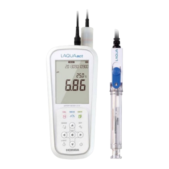
Names of each part Names of each part ■ ● Instrument Name Function Display Displays the measured value and set value and so on. Operation keys Used for instrument operation. Electrode connector Connects the BNC connector of the electrode. Temperature connector Connects the temperature connector of the electrode. -
Page 25: Display
Names of each part ● Display Two electrodes can be connected to measure two parameters at the same time with this instrument. The display is divided into the main screen and the sub screen, and you can select the channel displayed on the main screen. The selected channel can be identified with an icon. -
Page 26: Battery Level Display
Names of each part Name Function Standard solution When calibrating pH standard solution, the calibration history icon corresponding icon lights. Displays the unit for the measurement parameter and the display item. Unit display area This is displayed in the main screen and the sub screen, respectively. -
Page 27: Operation Key
Names of each part ● Operation key Name Function Changes the operation mode to the measurement mode during operation in a different mode. The changes you made using the setting mode are reflected when you press MEAS key this key to return to the measurement mode. In the measurement mode, switches the automatic hold measurement on/off. -
Page 28: Basic Operation
Basic operation Basic operation ■ ● Changing the operation mode This instrument is operated by changing the operation mode from four available modes, depending on the purpose of use. The status icon indicates the current mode. You can change the operation mode using the corresponding key. However changing to the calibration, data, or setting mode is available only from the measurement mode. -
Page 29: Switching The Displays
Basic operation ● Switching the displays You can switch the channel between the main screen and the sub screen. In the measurement mode, pressing the keys can switch the channels between the main screen and the sub screen. When performing calibration or setting, switch the display to show the desired channel (measurement parameter) on the main screen. -
Page 30: Changing The Measurement Parameter
Basic operation ● Changing the measurement parameter This instrument can measure multiple parameters. For measurement, an electrode corresponding to the measurement parameter is required. In the measurement mode, the measurement parameter can be changed by pressing the key. This operation is available for the channel that is shown on the main screen. <... -
Page 31: Using The Backlight
Basic operation ● Using the backlight When it is difficult to see the screen in a dark location, you can turn on the backlight by pressing the key. If the backlight is not operated for 5 minutes, it automatically turns off. -
Page 32: Entering Numeric Values
Basic operation ● Entering numeric values When entering numeric values to make various settings and set a calibration value, you can change the selected digit using the keys and increment or decrement the value (0 to 9) using the keys. -
Page 33: Measurement
Measurement This section describes the basic measuring method of each measurement parameter. ■ Preparation ................. 12 ● Confirmation before starting measurement ........12 ● Turning ON the instrument..............13 • Inserting the batteries ..................13 • Using the AC adapter (option) ................14 •... -
Page 34: Preparation
Preparation Preparation ■ ● Confirmation before starting measurement ・ Have you prepared the appropriate electrode for the measurement parameter? ⇒ If not, purchase the appropriate electrode. ・ Is the prepared electrode in good condition? ⇒ If the responsive part is stained or damaged, it may not be possible to obtain ... -
Page 35: Turning On The Instrument
Preparation ● Turning ON the instrument • Inserting the batteries This instrument is operated by batteries. You can use AAA alkaline batteries or AAA Ni- MH rechargeable batteries. Perform the following procedure to insert batteries in the instrument. 1. To unlock the battery cover, turn the knob on the battery cover on the back of the instrument counterclockwise. -
Page 36: Using The Ac Adapter (Option)
Preparation • Using the AC adapter (option) It is possible to use the AC adapter to operate the instrument. Perform the following procedure to connect AC adapter to the instrument. The AC adapter is an option. To purchase it, contact your dealer. (Refer to “ Options ” (page 94).) 1. -
Page 37: Setting The Date And Time
Preparation ● Setting the date and time When using the instrument for the first time or after replacing the batteries, set the date and time. After setting, the date and time data is displayed correctly when saving data in the internal memory. If the setting is incorrect, the date and time of saved data becomes incorrect. -
Page 38: Connecting An Electrode
Preparation To change to the setting again, press the key to return to the "DATE" (date and time setting) screen. The settings on screen before the key is pressed are not saved. ● Connecting an electrode To perform measurement, you must use the proper electrode for measurement items being measured. -
Page 39: Ph Measurement
pH measurement pH measurement ■ You can measure the pH of the sample with a pH electrode. Use a combination electrode incorporating a glass electrode and a reference electrode for measurement. A single glass electrode cannot be used with this instrument. pH can be measured using channel 1 of the instrument. -
Page 40: Setting The Standard Solution Used For Calibration (Default: Nist)
pH measurement 3. Press the keys to select the "ATC" (automatic temperature compensation) or the "MTC" (manual temperature compensation) and then press the key. 4. If you select the "MTC", enter the temperature to be compensated for and then press the key. -
Page 41: Standard Solution Type
pH measurement • Standard solution type Standard solution type Description Set to use the standard solution of the Japanese specification. NIST (Japanese specification) Standard solution icon Set to use the standard solution of the USA specification. (USA specification) Standard solution icon Set to use the standard solution of an optional specification. -
Page 42: Performing Calibration
pH measurement ● Performing calibration Calibration is necessary to measure pH accurately. We recommend performing calibration once a day, before the first measurement. According to the following procedure, perform calibration accurately. Note ・ Perform two-point calibration using pH 7 and pH 4 when you know that the sample is acidic;... - Page 43 pH measurement 5. Check that the pH value is stable while the pH electrode is immersed in the standard solution, then press the key. Stabilization judgment starts and the HOLD icon blinks. When the value is stabilized, the HOLD icon changes from the blinking state to the lit state and calibration to the standard solution value at the measured temperature is performed.
- Page 44 pH measurement ・ You can cancel calibration by pressing the key while the HOLD icon is blinking. ・ The order of calibration of the standard solution is optional. In the above example, you can calibrate pH 4 first and then pH 7. Note If calibration of any standard solution is performed again in the calibration mode, only the value of calibrated solution is updated.
-
Page 45: Inspecting Repeatability
pH measurement • Inspecting repeatability You can inspect repeatability using the pH 7 standard solution by pressing the key on the screen after calibration. Measure the pH 7 standard solution by using the calibrated electrode to display the absolute value of the difference between the measured value and standard solution value. -
Page 46: Ph Standard Solution Setting Is Cust
pH measurement • pH standard solution setting is CUST This section describes the procedure for two-point calibration. 1. Press the key to enter the calibration mode and enter the standard solution value for the 1st point calibration. The current measured value is displayed on the sub screen. 2. - Page 47 pH measurement 5. While the pH electrode is immersed in the standard solution, press the key. Stabilization judgment starts and the HOLD icon blinks. When the value is stabilized, the HOLD icon changes from the blinking state to the lit state and calibration to the set standard solution value is performed.
- Page 48 pH measurement You can cancel calibration by pressing the key while the HOLD icon is blinking. Note If calibration of any standard solution is performed again in the calibration mode, only the value of calibrated solution is updated. If you change to the measurement mode and then enter the calibration mode to perform calibration again, all previous data is updated.
-
Page 49: Performing Measurement
pH measurement ● Performing measurement You can perform measurement in the measurement mode by immersing the pH electrode in the sample. Also, you can use the automatic hold function to perform stability judgment of the measured value. 1. Wash the pH electrode with pure water (or deionized water) and wipe it with filter paper or tissue paper. -
Page 50: Mv, Orp Measurement
mV, ORP measurement mV, ORP measurement ■ The mV measurement measures the electromotive force between the electrode and the sample by using a pH electrode. The measured value can be used to understand the status of the electrode after using the standard solution. The ORP measurement measures the ORP (oxidation-reduction potential) of the sample by using an ORP electrode. -
Page 51: Switching Between Absolute Value And Relative Value
mV, ORP measurement 3. Press the keys to select the "ATC" (automatic temperature measurement) or the "MTC" (manual temperature display) and then press the key. 4. If you select the "MTC", enter the temperature to be displayed and then press key. -
Page 52: Performing Measurement
mV, ORP measurement ● Performing measurement You can perform measurement in the measurement mode by immersing the electrode in the sample. Also, you can use the automatic hold function to perform stability judgment of the measured value. 1. Wash the electrode with pure water (or deionized water) and wipe it with filter paper or tissue paper. -
Page 53: Conductivity Measurement
Conductivity measurement Conductivity measurement ■ The conductivity cell can be used to measure the conductivity, salinity, TDS, and resistivity of a sample. Salinity, TDS, and resistivity are calculated from the measured value of conductivity. Press the key to select the measurement parameter (“ Changing the measurement parameter ”... -
Page 54: Setting The Instrument
Conductivity measurement ● Setting the instrument • Setting the temperature display (default: ATC) When a conductivity cell with a temperature sensor is used, or a conductivity cell without a temperature sensor is used with a temperature electrode, the automatic temperature measurement function can be used. -
Page 55: Setting The Conductivity Unit (Default: S/Cm)
Conductivity measurement • Setting the conductivity unit (default: S/cm) You can select the conductivity unit from three types, S/cm, S/m, mS/cm FIX (fixed at mS/cm). Select the unit depending on your application. When measuring resistivity, these units correspond to Ω·cm, Ω·m, Ω·cm (for mS/cm FIX). -
Page 56: Setting The Salinity Unit (Default: Ppt)
Conductivity measurement • Setting the salinity unit (default: PPT) You can select the salinity unit from PPT or %. Select the unit depending on your application. 1. Press the key to enter the setting mode. 2. Press the keys to select the "UNIT (SAL)" (salinity unit setting) and then press the key. -
Page 57: Setting The Cell Constant (Default: 1.000×1.0 Cm-1)
Conductivity measurement • Setting the cell constant (default: 1.000×1.0 cm A cell constant is set for each conductivity cell. To measure conductivity correctly, the cell constant of the conductivity cell must be set in the instrument. 1. Press the key to enter the setting mode. 2. -
Page 58: Setting The Temperature Conversion
Conductivity measurement • Setting the temperature conversion (Default: ON, 2.00%/°C) The measured value of a sample that is not at 25°C can be converted to a value at 25°C. The temperature characteristics of the conductivity vary by sample. To use the temperature conversion function correctly, temperature coefficient (the rate of change per 1°C of the conductivity) must be set for each sample. -
Page 59: Performing Conductivity Calibration
Conductivity measurement ● Performing conductivity calibration A verified cell constant is printed on a label of the conductivity cell. However, the actual cell constant may fluctuate depending on the usage circumstances and it is desirable to calibrate the cell constant in that case. The procedures of cell constant calibration are shown below. - Page 60 Conductivity measurement You can suspend calibration by pressing the key while the HOLD icon is blinking. Note The conductivity value of the standard solution used in the calibration process is the compensated value into the calibrating temperature by the temperature coefficient 2%/°C from the 25°C value....
-
Page 61: Performing Salinity Calibration
Conductivity measurement ● Performing salinity calibration The salinity is calculated from the value of the conductivity, however, one point calibration can be performed using the standard solution. Calibrate at the temperature indicated on the standard solution. 1. Press the key to change the measurement parameter to salinity. Refer to “... - Page 62 Conductivity measurement You can cancel calibration by pressing the key while the HOLD icon is blinking.
-
Page 63: Performing Measurement
Conductivity measurement ● Performing measurement Immersing the conductivity cell in the sample solution can perform measurement in the measurement mode. Also, you can use the automatic hold function to perform stability judgment of the measured value. 1. Press the key to change to the measurement parameter to measure. - Page 64 M E M O...
-
Page 65: Using Various Functions
Using Various Functions This section describes functions available in this instrument. ● Saving measurement data in the internal memory ......44 ● Displaying saved data................. 45 ● Deleting all saved data................ 46 ● Displaying the latest calibration and inspection data ..... 47 •... -
Page 66: Saving Measurement Data In The Internal Memory
Saving measurement data in the internal memory ● Saving measurement data in the internal memory Up to 1000 data items measured by the instrument can be stored in the internal memory of the instrument. The measurement data is saved in the internal memory in the measurement mode, except during the automatic hold measurement. -
Page 67: Displaying Saved Data
Displaying saved data ● Displaying saved data You can display the data saved in the internal memory. 1. Press the key to enter the data mode. 2. Press the keys to select "OUT" (display saved data) and then press the key. -
Page 68: Deleting All Saved Data
Deleting all saved data ● Deleting all saved data You can delete all data saved in the internal memory. However, you cannot delete a data individually. Copy or transfer necessary data to a PC for storage. 1. Press the key to enter the setting mode. 2. -
Page 69: Displaying The Latest Calibration And Inspection Data
Displaying the latest calibration and inspection data ● Displaying the latest calibration and inspection data You can display the latest pH calibration data and repeatability inspection data. • Displaying the latest calibration data 1. Press the key to enter the data mode. 2. -
Page 70: Displaying The Latest Inspection Data
Displaying the latest calibration and inspection data ・ Electrode status based on calibration result Display Description Reference Electrode sensitivity: 93% to 100% GOOD - Good condition. Electrode sensitivity: 90% to 93% CHECK Urgent measures are not required but attention is P. -
Page 71: Deleting Calibration Data
Deleting calibration data ● Deleting calibration data You can delete the calibration data set in the instrument. 1. Press the key to enter the setting mode. 2. Press the keys to select the "MAINT" (maintenance setting) and then press key. 3. - Page 72 Deleting calibration data 5. Select "YES" to delete the calibration data, or select "NO" to cancel deleting it. And then press the key. When "YES" is selected, "END" appears after deletes calibration data. Press the key. To return to the setting mode, press the key.
-
Page 73: Printing Measured Values And Calibration Data
Printing measured values and calibration data ● Printing measured values and calibration data You can print out the measured value or calibrated value displayed on the instrument, or the measurement data or the calibration data saved in the instrument. If repeatability inspection has been inspected, the inspection data is printed out with the calibration data. - Page 74 Printing measured values and calibration data < Measurement data > Printout format Description Date : 2013/09/01 Measurement date Time : 09:00 Measurement time Channel Measurement Channel : 5.22 Measured value HOLD status HOLD : AUTO Hold value: AUTO Not hold value: INST Temperature : 25.5°C ATC Temperature value and temperature setting...
- Page 75 Printing measured values and calibration data < The data saved in internal memory > Printout format Description Memory Num : 0001 Data number Date : 2013/09/01 Measurement date Time : 09:00 Measurement time Channel Measurement Channel : 5.22 Measured value HOLD status HOLD : INST...
- Page 76 Printing measured values and calibration data < Calibration data (pH, inspection was performed) > Printout format Description Inst. model : D-74 * Instrument model (*Suffix G is not printed.) Inst. SN : KL1TSN20 Instrument serial number Elect. status : GOOD Electrode status based on calibration result Offset : 0.7 mV...
- Page 77 Printing measured values and calibration data < Inspection data (pH) > Printout format Description Inst. model : D-74 * Instrument model (*Suffix G is not printed.) Inst. SN : KL1TSN20 Instrument serial number Calibration data Date : 2013/09/01 Calibration date Time : 09:00 Calibration time...
-
Page 78: Transferring Saved Data To A Pc
Transferring saved data to a PC ● Transferring saved data to a PC By using a serial cable (“ Options ” (page 94)) to connect the instrument to a PC, you can transfer the saved data to the PC and edit it. Connect the serial connector at the instrument side to the serial port on the PC. -
Page 79: Operating The Instrument From An External Device
Operating the instrument from an external device ● Operating the instrument from an external device You can remotely operate the instrument from an external device (ex. PC) via the RS- 232C communication. Use the serial cable to connect the serial connector on the instrument side and the serial port on the PC. -
Page 80: Using The Automatic Data Save (Default: Off)
Using the automatic data save (default: OFF) ● Using the automatic data save (default: OFF) You can automatically save data in the internal memory at the specified interval. While using this function, the automatic power off setting is disabled. If the batteries run out while using the automatic data save function, the data saved until just before the batteries run out. - Page 81 Using the automatic data save (default: OFF) 4. Press the key to enter the measurement mode. When this setting is "ON", "AUTO LOG", which indicates that the automatic data save function is on, is displayed. 5. Pressing the key starts saving the data (when the setting is "ON"). Pressing the key again stops the data saving process.
-
Page 82: Setting The Id Number (Default: 000)
Setting the ID number (default: 000) ● Setting the ID number (default: 000) You can set an ID number to differentiate the sample of the data to be saved. When the data is saved in the internal memory, the ID number entered in this setting is saved together with the data. -
Page 83: Using The Calibration Interval Alarm (Default: Off)
Using the calibration interval alarm (default: OFF) ● Using the calibration interval alarm (default: OFF) If calibration has not been performed in pH measurement or calibration has not been performed for a certain period of time after calibration is performed, "ERR No. 0008" is displayed to prevent forgetting to perform calibration. -
Page 84: Calibrating Temperature Sensor
Calibrating temperature sensor ● Calibrating temperature sensor The temperature sensor or temperature compensation electrode in the combination electrode has ±1°C accuracy without calibration. You can use a known temperature solution to calibrate the temperature sensor. 1. Immerse the electrode into the solution until the temperature sensor is immersed. -
Page 85: Changing The Automatic Power Off Setting (Default: Off)
Changing the automatic power off setting (default: OFF) ● Changing the automatic power off setting (default: OFF) You can set the instrument to automatically turn OFF when there is no key operation for a certain period of time. This function is disabled during automatic data memory saving or remote operation using an external device. -
Page 86: Performing Test Printing Of The Printer Unit
Performing test printing of the printer unit ● Performing test printing of the printer unit In order to check whether the printer unit is operating correctly or there is a printer com- munication problem, you can perform test printing. Connect the instrument and a printer correctly and perform the following procedure for test printing. -
Page 87: Resetting To Factory Default Settings
Resetting to factory default settings ● Resetting to factory default settings The instrument settings can be reset to the factory default settings. The calibration data is deleted but the data of date and time, and the saved data are not deleted. Make sure there will be no problems before using this function. - Page 88 M E M O...
-
Page 89: Maintenance
Contact for maintenance Maintenance This section describes maintenance of the instrument and the electrodes that are used with the instrument. To use them for a long period, perform the described maintenance procedures appropriately. ● Contact for maintenance Manufacturer: HORIBA Advanced Techno Co., Ltd. 31, Miyanonishi-cho, Kisshoin Minami-ku, Kyoto 601-8306, Japan ●... -
Page 90: Maintenance And Storage Of The Ph Electrode
Maintenance and storage of the pH electrode ● Maintenance and storage of the pH electrode For the detailed procedures for maintaining and storing electrodes, refer to the instruction manual for each electrode. This section describes an overview of the procedures for maintenance and storage to be performed as part of daily use. •... -
Page 91: Maintenance And Storage Of The Orp Electrode
Maintenance and storage of the ORP electrode ● Maintenance and storage of the ORP electrode For the detailed procedures for maintaining and storing electrodes, refer to the instruction manual for each electrode. This section describes an overview of the procedures for maintenance and storage to be performed as part of daily use. •... -
Page 92: Checking The State Of The Orp Electrode
Checking the state of the ORP electrode ● Checking the state of the ORP electrode ORP standard solution can be used to check the state of the ORP electrode. This solution is only used to check the state of the ORP electrode; it is not used to calibrate the instrument. -
Page 93: Maintenance And Storage Of The Conductivity Cell
Maintenance and storage of the conductivity cell ● Maintenance and storage of the conductivity cell For the detailed procedures for maintaining and storing cells, refer to the instruction manual for each cell. This section describes an overview of the procedures for maintenance and storage to be performed as part of daily use. - Page 94 M E M O...
-
Page 95: How To Resolve Errors Or Troubles
When an error message appears How to Resolve Errors or Troubles This section describes the causes of typical problems and the actions to be taken, including questions frequently asked by customers. Check these before contacting us. When an error message appears ■... -
Page 96: Err No.0002 Empty Battery Level
When an error message appears ● ERR No.0002 Empty battery level The instrument cannot operate properly because the battery level is empty. Cause How to solve problem The battery level is empty. Replace the batteries or connect the AC adapter (option). ●... -
Page 97: Err No.0005 Electrode Sensitivity Error
When an error message appears ● ERR No.0005 Electrode sensitivity error Detected that the electrode sensitivity is out of the setting range that allows proper measurement. Cause How to solve problem The electrode is dirty. Clean the electrode. The electrode is cracked. Replace the electrode. -
Page 98: Err No.0008 Calibration Interval Error
When an error message appears ● ERR No.0008 Calibration interval error ・ More than the set number of days has elapsed since calibration was last performed. ・ The calibration interval alarm is "ON" and calibration has not been performed. Cause How to solve problem Calibration has not been... -
Page 99: Troubleshooting
Troubleshooting Troubleshooting ■ This section describes causes and actions to take for problems that customers frequently ask us. ● The indicated value fluctuates < There is a problem with the electrode > Cause How to solve problem The electrode is dirty. Clean the electrode. -
Page 100: The Response Is Slow
Troubleshooting ● The response is slow Cause How to solve problem The electrode is dirty. Clean the electrode. The electrode is cracked. Replace the electrode. The wrong internal solution is Use the correct internal solution. being used. It is important to select an electrode that is appropriate for the sample. -
Page 101: The Measured Value Blinks
Troubleshooting ● The measured value blinks The measured value blinks when it is out of the measurement range. Cause How to solve problem Sample is out of the Use a sample within the measurement range. measurement range. The electrode must be immersed up to the liquid junction. Electrode is not immersed As a guide, immerse to at least 3 cm from the tip of the enough to cover liquid junction. -
Page 102: Repeatability Of The Measured Value Is Poor
Troubleshooting ● Repeatability of the measured value is poor Cause How to solve problem Repeatability becomes poor when the pH of the sample Effect of the sample solution changes over time. Clean the electrode. (Electrode cleaning solution 220 or The electrode is dirty. 250 is recommended.) The electrode is cracked. -
Page 103: Part Of The Display Is Missing
Troubleshooting ● Part of the display is missing If part of the display is missing, it is the Instrument defect. Contact your dealer. It is possible to check part of the display is missing. The display can be set to full screen display. - Page 104 M E M O...
-
Page 105: Appendix
Main specifications Appendix This section describes the specifications of the instrument, default settings, measurement principles, and other technical information. Options for the instrument are also described. Main specifications ■ Item Contents Model D-74G Brand (pet name) LAQUAact Portable pH Water Quality Meter Series name Model description pH/ORP/Conductivity Meter... - Page 106 Main specifications Measurement Item Description parameter Measuring principle 2 AC bipolar method : 0.00 S/cm to 200.0 mS/cm Cell constant 1 cm Measuring range : 0.000 S/cm to 20.00 mS/cm Cell constant 0.1 cm (Display range) Conductivity : 0.0 S/cm to 2.000 S/cm Cell constant 10 cm Resolution 0.05% of full scale...
-
Page 107: Table Of Conductivity Cell Range
Main specifications ● Table of conductivity cell range ・ Unit: S/m Cell constant Range 1000 m 100 m 10 m 20.0 to 199.9 S/m 2.00 to 19.99 S/m 0.200 to 1.999 S/m 20.0 to 199.9 mS/m 2.00 (0.00) to 19.99 mS/m 0.200 (0.000) to 1.999 mS/m 0.0 to 199.9 µS/m ・... -
Page 108: Table Of Conductivity Cell Range (Resistivity Range)
Main specifications ● Table of conductivity cell range (resistivity range) ・ Unit: Ω·m Cell constant Range 10 m 100 m 1000 m 0.200 to 1.999 MΩ·m 20.0 to 199.9 kΩ·m 2.00 to 19.99 kΩ·m 0.200 to 1.999 kΩ·m 20.0 (0.0) to 199.9 Ω·m 2.00 (0.00) to 19.99 Ω·m 0.000 to 1.999 Ω·m ・... -
Page 109: Instrument Default Settings
Instrument default settings Instrument default settings ■ Measurement Selection item/Setting Item Default values range parameter Automatic (ATC)/ Temperature setting Automatic (ATC) Manual (MTC) Temperature input value 0.0°C to 100.0°C 25.0°C Auto power off ON/OFF Common Auto power off time 1 min to 30 min 30 min Sample ID 000 to 2999... -
Page 110: Technical Note
Technical note Technical note ■ ● pH measurement (glass electrode) In the glass electrode method, the known pH of a reference solution is determined by using two electrodes, a glass electrode and a reference electrode, and measuring the voltage (difference in potential) generated between the two electrodes. The difference in pH between solutions inside and outside the thin glass membrane creates electromotive force in proportion to this difference in pH. -
Page 111: Ph Standard Solutions At Various Temperatures
Technical note ● pH standard solutions at various temperatures < NIST > pH 7 pH 12 Temp. pH 2 pH 4 pH 9 Neutral Saturated calcium (°C) Oxalate Phthalate Borate phosphate hydroxide solution 1.666 4.003 6.984 9.464 13.423 1.668 3.999 6.951 9.395 13.207... -
Page 112: Orp Measurement
Technical note ● ORP measurement ORP is an abbreviation for oxidation-reduction potential. ORP is the energy level (potential) determined according to the state of equilibrium between the oxidants (M (z-n)+ and reductants (M ) that coexist within a solution. For one type of equilibrium in a solution: .......... -
Page 113: Conductivity Measurement
Technical note ● Conductivity measurement Conductivity is an index that expresses the ease with which electric current flows through a material. Conductors are categorized either as electron conductors (such as metals and other substances which use free electrons to conduct electricity) or ion conductors (such as electrolytic solution or fused salt, which use ions to conduct electricity). -
Page 114: Conductivity Standard Values At Various Temperature
Technical note ● Conductivity standard values at various temperature Conductivity value at 25°C Temp. (°C) 84.00 (S/cm) 1413 (S/cm) 12.88 (mS/cm) 111.8 (mS/cm) 64.01 7.15 65.4 65.00 8.22 74.1 67.00 1020 9.33 83.2 68.00 1147 10.48 92.5 70.00 1173 10.72 94.4 71.00 1199... -
Page 115: For More Information
For more information For more information ■ This manual describes pH measurement, ORP measurement and conductivity measurement. For detailed information, see "The Story of pH and Water quality" on our website. This page presents the knowhow we have cultivated over many years, for example, how temperature affects measured values and what to do when you want to measure various samples. -
Page 116: Options
Options Options ■ A wide variety of electrodes and options are available for use with the instrument. You can select the optimum electrode and options for your application and objectives. These options can be purchased from your nearest agency. Please provide the part name and part number to the representative. - Page 117 31, Miyanonishi-cho, Kisshoin Minami-ku, Kyoto 601-8306, Japan http://www.horiba-adt.jp For any questions regarding this product, please contact your local agency, or inquire from the following website. http://global.horiba.com/contact_e/index.htm...
Need help?
Do you have a question about the LAQUAact D-74G and is the answer not in the manual?
Questions and answers