
Related Manuals for DFI GM330-BFF


Summary of Contents for DFI GM330-BFF
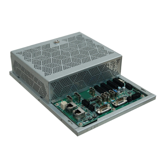
- Page 1 GM330-BFF Gaming Computing System User’s Manual Preliminary Version A57000939 Chapter 1 Introduction...
- Page 2 Copyright FCC and DOC Statement on Class B This publication contains information that is protected by copyright. No part of it may be re- This equipment has been tested and found to comply with the limits for a Class B digital produced in any form or by any means or used to make any transformation/adaptation without device, pursuant to Part 15 of the FCC rules.
-
Page 3: Table Of Contents
Battery ................... 23 Key Features ................6 Chapter 6 - Mounting ....... 26 Specifications ................7 Getting to Know the GM330-BFF ..........8 Chapter 7 - BIOS Setup ......27 Mechanical Dimensions ............9 Chapter 8 - Supported Software ....38 Chapter 3 - Installing Devices ....11 Connecting the I/O Board ............ -
Page 4: About This Manual
About this Manual Static Electricity Precautions An electronic file of this manual can be obtained from the DFI website at www.dfi.com. To It is easy to inadvertently damage your PC, system board, components or devices even before download the user’s manual from our website, please go to Support > Download Center. On installing them in your system unit. -
Page 5: Safety Precautions
• Unplug the power cord before removing the system chassis cover for installation or servic- ing. After installation or servicing, cover the system chassis before plugging the power cord. • GM330-BFF system unit • Mounting screws for M.2 modules • Danger of explosion if battery incorrectly replaced. -
Page 6: Chapter 1 - Introduction
Chapter 1 Chapter 1 - Introduction Overview Key Features Model Name GM330-BFF Processor AMD Embedded G-Series I ,J and JX Family SoCs Audio Speaker and 5.1 Channel Audio Output S/PDIF Digital Output Two LAN ports One RS-232 (DB-9 connector) One RS-232/422/485 (DB-9 connector) -
Page 7: Specifications
Chapter 1 Specifications Power • 12V DC-in (4-pin Vertical Connector) ® Processor System GX-217GI, Dual Core, 1MB Cache, 4 CU, 1.7GHz (2.0GHz), 12-15W ® GX-224IJ, Dual Core, 1MB Cache, 3 CU, 2.4GHz (2.8GHz), 10-15W Environment • Temperature - Operating: 0 C ~ 45 ®... -
Page 8: Getting To Know The Gm330-Bff
Chapter 1 Getting to Know the GM330-BFF Front View Speaker and 5.1 ch audio Connects an audio I/O module to the 4-pin speaker connector for stereo (4.5W+4.5W) speak- ers and 5.1 ch audio connector for audio sound systems; there is also an S/PDIF digital audio connector. -
Page 9: Mechanical Dimensions
Chapter 1 Mechanical Dimensions Chassis Dimension Front View Right View Left View Top View 63.00 67.00 Rear View 270.00 Chapter 1 Introduction... - Page 10 Please refer to your operating system manual for instructions on installing an operating system. Installing the Drivers The system comes with a software package including drivers. These drivers must be installed to provide the best system performance. Refer to the Supported Software Chapter for instructions on installing drivers. Chapter 2 Getting Started www.dfi.com...
-
Page 11: Chapter 3 - Installing Devices
Chapter 3 Chapter 3 - Installing Devices Powering on the System and Connecting the Display Connecting the I/O Board To power on the system, simply connect the 4-pin power cable to the system and the system will The system supports 32 digital inputs and outputs. The I/O board that came with the package be automatically powered on. -
Page 12: Removing The Chassis Cover
Chapter 3 Removing the Chassis Cover Installing a SODIMM Please observe the following guidelines before opening the chassis cover: The system supports two DDR4 SODIMM sockets. Retention Notch Make sure the system and all other peripherals connected to it have been powered off. Notch Disconnect all power cords and cables. -
Page 13: Installing An M.2 Card
Chapter 3 Installing an M.2 card Installing a SATA DOM The system has one M.2 type 2280 socket (M Key), which provides PCIe NVMe x4 interface that The system board is equipped with two SATA 3.0 ports that support the installation of SATA supports the installation of an M.2 22 x 80mm SSD card. -
Page 14: Chapter 4 - Jumper Settings
Chapter 4 Chapter 4 - Jumper Settings FPGA Programming Mode Select Clear CMOS Data Note: GX-217GI supports only one DIMM slot Power LED Note: GX-217GI supports only one DIMM slot Power LED DC_in DC_in HDD LED LAN 1 LAN 2 HDD LED LAN 1 LAN 2... -
Page 15: Mcu Programming Mode
Chapter 4 MCU Programming Mode Note: GX-217GI supports only one DIMM slot Power LED DC_in HDD LED LAN 1 LAN 2 Power Button Reset Button DP 0 SATA 3.0 COM 2 DP 1 COM 3 COM 4/5 ® SATA 1 GX-217GI USB 2.0_4 GX-224IJ... -
Page 16: Chapter 5 - Ports And Connectors
Chapter 5 Chapter 5 - Ports and Connectors Audio Ports 5.1 ch Audio Note: GX-217GI supports only one DIMM slot Pins Pins Pin Assignment Power LED DC_in Assignment HDD LED LAN 1 LAN 2 Power Button Reset Button DP 0 LINEOUT-L LINEOUT-R SATA 3.0... -
Page 17: Usb Ports
Chapter 5 USB Ports DC-in USB 2.0 Note: GX-217GI supports only one DIMM slot Power LED Note: GX-217GI supports only one DIMM slot Power LED DC_in DC_in HDD LED LAN 1 LAN 2 HDD LED LAN 1 LAN 2 Power Button Power Button Reset Button DP 0... -
Page 18: Com Ports
Chapter 5 COM Ports COM 1 (RS232/RS422/RS485) / COM 2 (RS232) 1 2 3 4 5 1 2 3 4 5 1 2 3 4 5 COM 2: RS232 Note: GX-217GI supports only one DIMM slot Power LED 6 8 9 DC_in HDD LED LAN 1... -
Page 19: Rj45 Lan Ports
Chapter 5 RJ45 LAN Ports Intrusion Door LAN 1 LAN 2 Note: GX-217GI supports only one DIMM slot Power LED Note: GX-217GI supports only one DIMM slot Power LED DC_in HDD LED DC_in LAN 1 LAN 2 HDD LED LAN 1 LAN 2 Power Button Power Button... -
Page 20: Display Outputs
Chapter 5 Display Outputs Digital Inputs/outputs Note: GX-217GI supports only one DIMM slot Note: GX-217GI supports only one DIMM slot Power LED Power LED DC_in DC_in HDD LED HDD LED LAN 1 LAN 2 LAN 1 LAN 2 Power Button Power Button Reset Button DP 0... - Page 21 Chapter 5 The Digital I/O connector provides 32-bit digital inputs or outputs to enable monitor and control of the states of the connected external devices. The recommended application voltage range is from 0 V to 24 V. The digital I/O ports support Electrostatic discharge (ESD) protection to prevent damage from ESD strikes between two connected devices.
-
Page 22: I/O Connectors
Chapter 5 I/O Connectors CPU Fan Connector Expansion Connectors M.2 Type 2280 (PCIe 3.0 x4) Note: GX-217GI supports only one DIMM slot Note: GX-217GI supports only one DIMM slot Power LED Power LED DC_in DC_in HDD LED HDD LED LAN 1 LAN 2 LAN 1 LAN 2... -
Page 23: Leds
Chapter 5 LEDs Battery Note: GX-217GI supports only one DIMM slot Power LED DC_in HDD LED Note: GX-217GI supports only one DIMM slot LAN 1 LAN 2 Power LED DC_in Power Button HDD LED LAN 1 LAN 2 Reset Button DP 0 Power Button Reset Button... - Page 24 Chapter 5 SATA (Serial ATA) Connectors LPC Connector Note: GX-217GI supports only one DIMM slot Power LED DC_in HDD LED LAN 1 LAN 2 Note: GX-217GI supports only one DIMM slot Power LED Power Button DC_in HDD LED Reset Button DP 0 LAN 1 LAN 2...
- Page 25 Chapter 5 5V DC-out Note: GX-217GI supports only one DIMM slot Power LED DC_in HDD LED LAN 1 LAN 2 Power Button Reset Button DP 0 SATA 3.0 COM 2 DP 1 COM 3 COM 4/5 ® SATA 1 GX-217GI USB 2.0_4 GX-224IJ GX-220IJ...
-
Page 26: Chapter 6 - Mounting
Drill 4 holes in the wall and insert screw bolts into the holes. Drill the screws into the screw anchors. Hang the device on the wall. The diagram on the right shows the screw holes and dimensions of wall mount (in millimeter). Screw hole Screw hole Chapter 6 Mounting Options www.dfi.com... -
Page 27: Chapter 7 - Bios Setup
Chapter 7 Chapter 7 - BIOS Setup Legends Overview Keys Function The BIOS is a program that takes care of the basic level of communication between the CPU Right and Left Moves the highlight left or right to select a menu. and peripherals. - Page 28 Chapter 7 Insyde BIOS Setup Utility Advanced The Advanced menu allows you to configure your system for basic operation. Some entries are Main defaults required by the system board, while others, if enabled, will improve the performance of your system or let you set some features according to your preference. The Main menu is the first screen that you will see when you enter the BIOS Setup Utility.
- Page 29 Chapter 7 CPU Configuration ACPI Configuration This section configures the CPU. This section configures system ACPI parameters. Wake on LAN SVM Support Enable or disable WOL (wake-on-LAN) to wake the system through an Ethernet adapter. Enable or disable the CPU virtualization function. The default is enabled. The default is disabled.
- Page 30 Chapter 7 PCI Express Configuration This section configures the settings of PCI Express root ports. PCI Express Root Port Controls the PCIe signal of the M.2 Type 2280 slot. Enable or disable this PCI Express root port. The default is enabled. LAN 1 PCIe Speed Controls the PCIe signal of the LAN port 1.
- Page 31 Chapter 7 Peripheral Configuration SATA Configuration This section configures peripherals settings. This section configures SATA devices. It also shows the information about the installed SATA drives. SATA Trusted Platform Module Enable or disable the Serial ATA controller. The default is enabled. Enable or disable the connection to a TPM device via the onboard LPC connector.
- Page 32 Chapter 7 Video Configuration USB Configuration This section configures the video settings. This section configures the parameters of the USB devices. UMA Version Select USB Configuration Select the memory mode used for integrated graphics cards: Forced legacy UMA mode EHCI (default) or Auto.
- Page 33 Chapter 7 Super I/O PC Health Status This section configures the system super I/O chip parameters. This section displays PC health status. COM Port 1 to COM Port 5 Enable or disable the serial port (COM). Device Settings It shows the IO/IRQ settings for the COM port. COM Type (only available for Serial Port 1 and 3) Configure the serial port mode.
- Page 34 Chapter 7 Smart Fan Function This section sets the smart fan function. CPU Smart Fan Function CPU Smart Fan Function Enable or disable CPU mart fan control (the default is enabled). Enable or disable CPU mart fan control (the default is enabled). Boundary 1 to Boundary 4 Fix Fan Speed Count Set the boundary temperatures that determine the operation of the fan with different fan...
- Page 35 Chapter 7 Security This section configures the Trusted Platform Module (TPM) function. TPM Availability Set Supervisor Password Show or hide TPM availability and its configurations. Set the administrative password for entering the BIOS utility or upon the entering of the power-on self-test (POST) process. The length of the password must be greater TPM Operation than 1 character and less than or equal to 10 characters.
- Page 36 Chapter 7 Boot USB Boot Enable or disable USB boot from a flash drive. Quiet Boot Enable or disable the quiet boot function to configure the screen’s display between POST messages or the OEM logo at bootup. Select Disabled to display the POST mes- sages and select Enabled to display the OEM logo.
- Page 37 BIOS file and the firmware update utility. For instructions on how to update BIOS with the flash utility, please see https://www.dfi.com/ knowledge/video/31 from the Knowledge Base of the DFI website. Read file successfully. (path= “platform.ini”) Information Please do not remove the AC power Insyde H20FFT (Flash Firmware Tool) Version (SEG) 100.00.08.10...
-
Page 38: Chapter 8 - Supported Software
Chapter 8 - Supported Software The system requires you to install drivers for some devices to operate properly. To download the latest driver, please go to the DFI Download Center: http://www.dfi.com/DownloadCenter Once you are in the Download Center page, select your product or type the model name and click “Search”... - Page 39 4. Please wait while the software and drivers are being installed. 2. Choose between “Express Install” or “Custom Install”. The “Express Install” installs all the programs in the default folder. 5. Once the Radeon ™ Software has been successfully installed, choose “Restart Now”. Chapter 8 Supported Software www.dfi.com...
- Page 40 LAN Driver folder. After the software package has done preparing the software package, click “Next” to continue. 2. Click “Install” to start the installation. 3. Click “Finish” to exit the wizard after the installation is complete. Chapter 8 Supported Software www.dfi.com...
- Page 41 1. Setup is now ready to install WinDriver USB/PCI Version 12.3.0. Click “Next” to continue. 4. Please wait while the Setup is installing the driver. 2. Read the license agreement then click “Yes” to continue. 5. Click “Finish” to exit the Setup wizard. Chapter 8 Supported Software www.dfi.com...
Need help?
Do you have a question about the GM330-BFF and is the answer not in the manual?
Questions and answers