Hydac FluidAqua Mobil FAM 5 Operating And Maintenance Instructions Manual
Hide thumbs
Also See for FluidAqua Mobil FAM 5:
- Operating and maintenance instructions manual (114 pages)

Subscribe to Our Youtube Channel
Related Manuals for Hydac FluidAqua Mobil FAM 5


Summary of Contents for Hydac FluidAqua Mobil FAM 5
- Page 1 FAM 5 FluidAqua Mobil Operating and Maintenance Instructions English (translation of original instructions) Keep for future reference. Documentation no.: 4166129a...
-
Page 2: Imprint
Court of registration: Saarbrücken, HRB 17216 Executive directors: Mathias Dieter, Dipl.Kfm. Wolfgang Haering Documentation Representative Mr. Günter Harge c/o HYDAC International GmbH, Industriegebiet, 66280 Sulzbach / Saar Phone: +49 6897 509 1511 Fax: +49 6897 509 1394 E-mail: guenter.harge@HYDAC.com © HYDAC FILTER SYSTEMS GMBH All rights reserved. -
Page 3: Table Of Contents
Content Content Imprint ......................2 Documentation Representative ..............2 Content ......................3 Preface ......................7 Technical Support ..................7 Product modification ..................7 Warranty ...................... 7 Using the documentation ................8 General safety information ................8 Hazard symbols ................... 9 Mandatory action symbols used .............. - Page 4 Content Stationary unit .................... 29 Mobile unit ....................30 Hydraulic circuit ..................31 Technical specifications ................33 Mode of operation ..................34 Cleaning in Bypass Flow ................35 Purifying and transferring by pumping ............35 Unit setup and connection ................. 36 Setting up the unit ..................
- Page 5 Content Setting the program version, operating hours, language ....... 70 Loading new program version/language version ........71 Inserting the micro SD card and copying the program ....... 72 Configuration menu ..................73 Changing the configuration ................ 74 Leaving the configuration menu ..............74 Overview of menu structure ..............
- Page 6 Content Replacing the active carbon filter cartridge (optional / accessory)..110 Rotary vane vacuum pump FAM-5-x-x-x-xx-R-x-x-x-x ......111 Checking the oil level (FAM-5-x-x-x-xx-R-x-x-x-x) ......112 Filling/Refilling vacuum pump oil ............113 Emptying the vacuum pump / Draining the oil ........115 Changing the vacuum pump oil ............
-
Page 7: Preface
After modification or repair work that affects the safety of the product has been carried out on components, the product may not be returned to operation until it has been checked and released by a HYDAC technician. Please notify us immediately of any modifications made to the product whether by you or a third party. -
Page 8: Using The Documentation
General safety information Using the documentation Note that the method described for locating specific information does not release you from your responsibility of carefully reading all these instructions prior to starting the unit up for the first time and at regular intervals in the future. What do I want to know? I determine which topic I am looking for. -
Page 9: Hazard Symbols
General safety information Any residual hazards are indicated by general safety information and instructions and are described in the operating instructions. Observe all safety and warning instructions attached to the unit. They must always be complete and legible. Do not operate the unit unless all the safety devices are present. Secure the hazardous areas which may arise between the unit and other equipment. -
Page 10: Mandatory Action Symbols Used
General safety information Mandatory action symbols used These symbols are listed for all general safety information and instructions in these operating instructions which indicate particular dangers to persons, property or the environment. Follow the operating and maintenance instructions Wear eye protection Use a safety mask Used GHS symbols These symbols are listed for all general safety information and instructions in... -
Page 11: Signal Words And Their Meaning In The General Safety Information
General safety information Signal words and their meaning in the general safety information DANGER DANGER – The signal word indicates a hazardous situation with a high level of risk, which, if not avoided, will result lethal or serious injury. WARNING WARNING –... -
Page 12: Others Symbols Used
General safety information Others symbols used The following symbols found you in this operation instructions. Tip for handling the product Required tools Signs used for the required specialist personnel These symbols show the required training/knowledge for installation work and/or maintenance work. Specialist personnel –... -
Page 13: Observe Regulatory Information
General safety information Observe regulatory information Observe the following regulatory information and directives: • Legal and local regulations for accident prevention • Legal and local regulations for environmental protection • Country-specific regulations, organization-specific regulations Proper/designated use Use the unit only for the application described in the following. The FAM is for dewatering, filtering and degassing hydraulic and lubricating oils. - Page 14 General safety information Depending on the version (see model code), the FAM may only be used for the following media (see model code): FAM-xx-M-… Mineral oil, tested with mineral oil. Mineral oils acc. to DIN 51524 Gear oils acc. to DIN 51517, 51524 Other hydraulic and lubrication oils which require or are compatible with NBR seals.
-
Page 15: Improper Use Or Use Deviating From Intended Use
Any use extending beyond this or deviating therefrom shall not be considered intended use. HYDAC FILTER SYSTEMS GMBH will assume no liability for any damage resulting from such use. This risk is borne solely by the owner. - Page 16 General safety information Auxiliary personnel: such persons have been instructed in power unit operation and are aware of potential hazards due to improper use. Specialist personnel: such persons with corresponding specialist training and several years' work experience. They are able to assess and perform the work assigned to them, they are also able to recognize potential dangers.
-
Page 17: Wear Suitable Clothing
General safety information Wear suitable clothing Loosely worn clothing increases the danger of getting caught or wound up in rotating parts and the danger of getting snagged on projecting parts. You can be severely injured or killed. Wear close-fitting clothing. Do not wear any rings, chains or any other jewelry. -
Page 18: Electrical Hazards
Do not make any modifications (design modifications, extensions) to the FluidAqua Mobil without the prior consent of the manufacturer. All design modifications require written permission from HYDAC FILTER SYSTEMS GMBH Immediately replace any machine components which are not in perfect condition. -
Page 19: Stoppage In An Emergency (Emergency Stop)
Unpacking the unit Stoppage in an emergency (EMERGENCY STOP) In the event of an emergency, turn the main switch by 90° in a counter-clockwise direction to shut down the entire unit. The entire system is then voltage-free downstream from this switch. Normal pressure is restored to the vacuum column after ≈... -
Page 20: Transporting The Unit
Transporting the unit Transporting the unit CAUTION High empty weight (≈ 120 … 160 kg depending on the version) Danger of bodily injury ► Secure the FAM from tipping and rolling on inclined surfaces. NOTICE Using components for pushing/pulling The unit will be damaged ►... -
Page 21: Transporting The Unit Horizontally
Transporting the unit Transporting the unit horizontally Completely empty the unit as well as the rotary vane vacuum pump before transporting it horizontally, for example, in a vehicle and close all the connections. Close the air outlet of the vacuum pump using the matching suitable screw plugs. -
Page 22: Transporting The Unit Suspended On A Crane
Transporting the unit Transporting the unit suspended on a crane NOTICE Unsuitable lifting accessories The unit/components will be damaged/destroyed ► Use only suitable lifting accessories to raise or lash the FAM. ► Ensure that no forces from the lifting accessories are exerted on the components on the FAM. -
Page 23: Decoding The Type Label
Decoding the type label Decoding the type label FAM 5 Page 23 / 148 en-US BEWA FAM5 4166129a en-us 2019-03-04.docx 2019-03-04... - Page 24 Decoding the type label Item -> Description -> Type label for unit -> The type label for the electric control cabinet is located on the inside -> Type label for electric motor of the motor pump assembly -> Type label for the vacuum pump ->...
-
Page 25: Checking The Scope Of Delivery
Checking the scope of delivery Checking the scope of delivery Upon receiving the FAM check it for any damage in transit. Immediately report any damage in transit to the forwarding agent or the HYDAC department in charge. The following items are supplied:... -
Page 26: Unit Versions
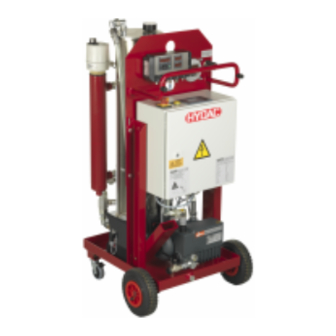
Description of unit Unit versions Stationary (FAM-x-1-..) Mobile (FAM-x-2-..) In comparison to the stationary version, the mobile version of the FAM also has: Wheels Swivel casters Suction hose Return hose FAM 5 Page 26 / 148 en-US BEWA FAM5 4166129a en-us 2019-03-04.docx 2019-03-04... -
Page 27: Components
Description of unit Components FAM 5 Page 27 / 148 en-US BEWA FAM5 4166129a en-us 2019-03-04.docx 2019-03-04... - Page 28 Description of unit Item Tool Drip tray 2.21 Wheels (only mobile FAM-5-x-2-…) 2.30 Steering castor (only mobile FAM-5-x-2-…) Vacuum column 3.68 Needle valve for vacuum setting 3.73 Air filter 3.85 Selector valve Motor pump assembly ContaminationSensor (FAM-xx-x-x-x-xx-x-x-xCx-…) Fluid filter for separating solid particles Vacuum pump Heater (FAM-xx-x-x-x-xx-x-H-…)
-
Page 29: Unit Dimensions
Unit dimensions Unit dimensions Stationary unit FAM 5 Page 29 / 148 en-US BEWA FAM5 4166129a en-us 2019-03-04.docx 2019-03-04... -
Page 30: Mobile Unit
Unit dimensions Mobile unit FAM 5 Page 30 / 148 en-US BEWA FAM5 4166129a en-us 2019-03-04.docx 2019-03-04... -
Page 31: Hydraulic Circuit
Hydraulic circuit Hydraulic circuit FAM 5 Page 31 / 148 en-US BEWA FAM5 4166129a en-us 2019-03-04.docx 2019-03-04... - Page 32 Hydraulic circuit Item Tool Drip tray 1.04 Leakage indicator in the drip tray Vacuum column 3.37 Pressure gauge for measuring the set vacuum 3.38 Vacuum column level sensor 3.43 Optical fluid level display of the vacuum column 3.68 Needle valve for vacuum setting 3.73 Air filter 3.85...
-
Page 33: Technical Specifications
Technical specifications Technical specifications The FAM is able to dewater authorized fluids down to a water content of less than 100 ppm and transformer oils down to less than 10 ppm. As an approximate guideline, the dimensioning of the FluidAqua Mobil can be defined in accordance with the tank volume. -
Page 34: Mode Of Operation
Mode of operation Mode of operation After being switched on, the motor pump assembly (4.0), depending on the fluid level, starts to suck the fluid in the vacuum column from the tank via the intake strainer (4.02) or from the vacuum column and the switch valve (3.85). The volumetric flow rate is divided in the volume flow divider (4.54). -
Page 35: Cleaning In Bypass Flow
Mode of operation Cleaning in Bypass Flow The FAM is connected with suction and pressure lines to the tank and cleans the medium to be found in it in constant bypass flow. Attach the FAM to the tank which is to be cleaned by means of a suction and pressure line and switch it on. -
Page 36: Unit Setup And Connection
Unit setup and connection Unit setup and connection CAUTION Outlet air of the rotary vane vacuum pump Hazardous to health ► Always make sure there is sufficient ventilation in the surrounding area of the unit. Air coming out of the rotary vane vacuum pump can contain particles of vacuum pump oil and/or the fluid. -
Page 37: Connection Overview
Unit setup and connection Connection overview The stationary and mobile FAM versions have different scopes of delivery. The stationary FAM has the positions 1 and 3, the mobile FAM additionally has the positions 5 and 7. Item FAM 5 1 FAM inlet connector 28L/M36x2 (external thread)* 2 adapters (accessory) Adapter G1 A (external thread)**... -
Page 38: Notes On Pipes And Hoses
Unit setup and connection Notes on pipes and hoses NOTICE Non-permitted pressure at the inlet IN / outlet OUT Risk of malfunctions ► Determine the pressure to be anticipated at the inlet/outlet with the prescribed values. Make sure that the cross-section of the connected hoses/piping is at least as large as the cross-section of the inlet/outlet port sizes. - Page 39 Unit setup and connection • Fluid density The pressure loss in straight pipes ( ∆ P ) can be calculated as follows: (line) Δp ≈ 6.8 * L / d * Q * V * D Δ = Pressure differential in [bar] = Pipe length [m] = Internal pipe diameter [mm] = Flow rate [l/min]...
-
Page 40: Connecting The Inlet (In)
Unit setup and connection Connecting the inlet (IN) The maximum permitted pressure P at the inlet to the FAM can be found e perm in the technical data. Use a negative pressure-resistant, flexible hose or a pipe for the suction-side connection. -
Page 41: Preparing The Vacuum Pump
Unit setup and connection Preparing the vacuum pump After delivery/transport by car, check the vacuum pump for the following points and prepare it accordingly for operation in compliance with the following steps: Step Tool Details on page Check air outlet Check the oil level (FAM-5-x-x-x-xx-R-x-x-x-x) Fill/refill the vacuum pump/drain oil... -
Page 42: Connecting The Unit Electrically
Unit setup and connection Connecting the unit electrically DANGER Exposed electrical components in the switch cabinet Danger of fatal injury due to electric shock ► Any work involving the electrical system may only be done by a properly trained, certified electrician. -
Page 43: Checking The Directionof Rotation Of The Electric Motor
Unit setup and connection Checking the directionof rotation of the electric motor Check the direction of rotation of the motor by switching it on briefly (jog mode). The FAM requires a clockwise rotating field of the connection socket. NOTICE Incorrect phase sequence / rotation direction of the electric motor The pumps will be destroyed. -
Page 44: Operating Elements On The Unit
Operating elements on the unit Operating elements on the unit The following operating elements can be found on the unit: Item Tool 3.37 Pressure gauge for measuring the set vacuum 3.48 Vacuum column drainage 3.68 Needle valve for setting the vacuum 7.27 Vacuum pump drainage Heater thermostat (FAM-xx-x-x-x-xx-x-H-…) - Page 45 Operating elements on the unit The control and display elements on the switch cabinet have the following functions: Item Control/display Function/designation element Main switch -> Main switch and emergency off Signal lamp -> Fault indicator lamp (yellow) Control panel -> START/STOP Selects operating mode Manual operation for manual activation of...
-
Page 46: Starting Up The Unit
Starting up the unit Starting up the unit NOTICE Automatic mode The unit starts and stops automatically in the "Dewater until" and "Filter until" operating modes. ► Depending on the local General Safety Information, a notice must be attached to the unit stating that the unit starts and stops automatically. NOTICE Connection IN / OUT closed The unit will suffer damage in the event of dry-running operation (>... -
Page 47: Start Screen (Home) And Menu Layout
Starting up the unit Start screen (HOME) and menu layout The FAM start screen (HOME) will be displayed if the unit was booted up without error. READY Dewater until Filter until Heat START OM MAN. SET The controls consist of the four function keys (4, 5, 6, 7), the ESC key (8), an ENTER key (9) and four arrow keys (10). -
Page 48: Menu Structure Of The Logo! Control Panel Tde
Starting up the unit Use the up ▲, down ▼, right ►, left ◄ arrow keys to move the cursor and change parameters Menu structure of the LOGO! control panel TDE By pressing the ▼ arrow key, the FAM Home start menu is displayed in the menu of the LOGO! control panel TDE. - Page 49 Starting up the unit FAM Home - Start menu READY Dewater Filter Heat START OM MAN. SET Inputs Outputs Analog inputs LOGO! TDE start menu Analog outputs Flag LOGO! TDE main menu -> Switch to Admin -> Network address LOGO! ->...
-
Page 50: Starting Operation
Starting up the unit Starting operation Check all hydraulic and electrical connections of the power unit in accordance with the Operation and maintenance Instructions enclosed with the FAM. After switch-on, the most recently selected operating mode will be shown in the READY display. - Page 51 Starting up the unit Vent the filter housing of the fluid filter. See page 55. Set the desired temperature on the heater (FAM-xx-x-x-x-xx-x-H-… ). See page 56. The unit is now in operation. If an AquaSensor AS is not installed or it is deactivated in the configuration menu (see page 73), then "0.0"...
-
Page 52: Setting The Pressure In The Vacuum Column
Starting up the unit Setting the pressure in the vacuum column Set the pressure in the vacuum column with the needle valve (3.68) and check the vacuum using pressure gauge (3.37). Note that the pressure to be set in the vacuum column is dependent, for example, on the operating medium, the operating viscosity, the air or the water content. - Page 53 Starting up the unit Lower pressure (e.g. -0.6 bar) means lower residual water content. Higher pressure (for example, -0.4 bar) means faster dewatering in case of free water. By closing the needle valve (D) you reduce the absolute pressure and also the air-flow rate for dewatering the operating medium.
-
Page 54: Pressure Information In The Vacuum Range
Starting up the unit Pressure information in the vacuum range Vacuum Absolute Absolute Relative Relative pressure pressure (gauge) (gauge) mbar mbar … … … … 5000 4000 4000 3000 3000 2000 2000 1000 1000 [8] Atmospheric pressure -100 -0,1 -200 -0,2 -300 -0,3... -
Page 55: Venting The Filter Housing
Starting up the unit Venting the filter housing WARNING Hot fluid Risk of burns ► Make sure that hot fluid can exit when bleeding. NOTICE Air in the fluid filter The filter element is not utilized completely ► Bleed the fluid filter after each shut-down/filter element replacement Bleed the fluid filter through the bleed screw (X) until fluid comes out. -
Page 56: Switching Heater On /Checking Setting (Fam-Xx-X-X-X-Xx-X-H
Starting up the unit Switching heater on /Checking setting (FAM-xx-x-x-x-xx-x-H-…) NOTICE Oils with high viscosity Functional issues Set the heater to ≈ 50°C with an oil viscosity ≥ 350 mm²/sec. ► If the temperature of the fluid is raised by 10-20°C, then the dewatering capacity increases by up to 50%. -
Page 57: Stopping Operation
Stopping operation Stopping operation Press the function key F2 "STOP". The power unit starts the after-run OPERATION phase. +13.0 %S +37.4°C Dewater until Filter until Heat STOP Version with integrated heater: The heater is switched OPERATION FOLLOW-UP PHASE off. The unit continues operation for 60 Cooling heater 56:76 s... -
Page 58: Switching Off The Unit
Switching off the unit Switching off the unit The unit can be switched off as follows after operations are stopped. Close all locking features in the inlet and outlet lines. Switch off the unit using the main switch (position: OFF) FAM 5 Page 58 / 148 en-US... -
Page 59: Selecting The Operating Mode
Selecting the operating mode Selecting the operating mode The operating mode cannot be changed during operation. Press the function key F2 "MODE". READY Dewater until Filter until Heat START MAN. Depending on the unit's equipment, four submenus are available to select DEWATER operating modes. -
Page 60: Operating Mode "Dewater" (Fam-Xx-X-X-X-Xx-X-X-Axx
Selecting the operating mode Change: Move: Done: ENTER 6. Confirm change with ENTER 7. Exit with ESC. Operating mode "Dewater" (FAM-xx-x-x-x-xx-x-x-Axx-…) This menu is displayed only if an AquaSensor AS is installed and activated in configuration menu. DEWATER External AS Dewater until Power on Power off... - Page 61 Selecting the operating mode Dewater until OFF: The operating medium is permanently dewatered. ON: The operating medium is dewatered until the set limit value for switching off is reached. The FAM then switches off. • Internal AquaSensor AS: Now the test interval starts (see page 65), the time until the FAM switches back on.
-
Page 62: Operating Mode "Filter" (Fam-Xx-X-X-X-Xx-X-X-Xcx
Selecting the operating mode Operating mode "Filter" (FAM-xx-x-x-x-xx-x-x-xCx-…) This menu is displayed only if a ContaminationSensor CS is installed and is activated in the configuration menu. FILTER Filter until HOME Description Filter until OFF: The operating medium is filtered permanently. ON: The operating medium is filtered until the limit value set in ContaminationSensor CS1000 is reached. - Page 63 Selecting the operating mode The limit for switching on, "UPPER", must be at least one class higher than the limit for switching off (LOWER) for each particle size class. Example: UPPER: ISO 20/19/18, LOWER: ISO 19/18/17 Mode 2 (M2) Switching output – Switching output –...
-
Page 64: Menu Structure Contaminationsensor Cs1000
Selecting the operating mode Menu structure ContaminationSensor CS1000 o.k. Measuring menu DSPLAY SWtOU switching output o.k. o.k. M2 mode 2 o.k. SP1 switch point o.k. MEAsCH test channel SAeMAX SAE A-D SAE Class A/B/C/D o.k. ISO 4 ISO class 4µm ISO 6 ISO class 6µm ISO 14... -
Page 65: Setting Times For "Dewater/Filter Until" (Optional)
Selecting the operating mode Setting times for "Dewater/Filter until" (optional) This menu is displayed only if an AquaSensor (FAM-xx-x-x-x-xx-x-x-Axx-…) and/or a ContaminationSensor CS (FAM-xx-x-x-x-xx-x-x-xCx-…) is installed and is activated in the configuration menu. INTER- Dewater/filter until: Test interval 00:60 Min. duration 00:10 HOME Description... -
Page 66: Operating Mode "Heat" (Fam-Xx-X-X-X-Xx-X-H
Selecting the operating mode Operating mode "Heat" (FAM-xx-x-x-x-xx-x-H-…) This menu is only displayed if a heater is installed and activated in the configuration menu. HEAT Heating HOME Description OFF: The operating medium is not heated. The heater is not in Heating operation. -
Page 67: Manual Operation
Selecting the operating mode Manual Operation In this menu, it is possible to empty the vacuum column and control the individual FAM components manually. Press the function key F3 "MANUAL". READY Dewater until Filter until Heat START MAN. Two submenus are available. -
Page 68: Emptying The Vacuum Column
Selecting the operating mode Emptying the vacuum column MANUAL Vacuum column EMPTY HOME START STOP Description YES = Vacuum column level switch ≤ MIN Vacuum column MIN NO = Vacuum column level switch > MIN Reset time Reset time remaining after fill level "Min" (the min. level in the vacuum column) is reached. -
Page 69: Manually Controlling Components
Selecting the operating mode Manually controlling components The individual components can have the following statuses: OFF: Inactive/not in operation MANUAL ON: Active/in operation [1] Pumps [2] Valve [3] Heater Description [1] Pumps Motor pump assembly and vacuum pump [2] Valve 3/2 directional valve ON: Suction from tank OFF: Suction from vacuum column... -
Page 70: Setting The Program Version, Operating Hours, Language
Setting the program version, operating hours, language Setting the program version, operating hours, language Press the function key F4 "SET". READY Dewater until Filter until Heat START MAN. Press on the appropriate function key F3/F4 to change the language. SETTINGS V00.34 Operating hrs. -
Page 71: Loading New Program Version/Language Version
Loading new program version/language version Loading new program version/language version A USB drive with other language versions is included in the scope of delivery. These can also be loaded to the PLC using a micro-SD card, which is also included in the scope of delivery. To do this, copy the desired language version "LOGO_U_P.bin"... -
Page 72: Inserting The Micro Sd Card And Copying The Program
Loading new program version/language version Inserting the micro SD card and copying the program Switch the unit off at the main switch (position: OFF) Carefully insert a screwdriver with a 3 mm blade into the slot on the front of the card edge socket and lift it partially out of the card slot. -
Page 73: Configuration Menu
Configuration menu Configuration menu The configuration menu is used to determine which optional components have been installed. Configuration is only required: • After loading a new program/language version. • To deactivate a defective component. After loading a new program version to the PLC, the display automatically switches to the Configuration menu. -
Page 74: Changing The Configuration
Configuration menu Changing the configuration 1. Press and hold the ESC key. The cursor appears. 2. Use the up ▲ or down ▼ arrow keys to select the desired position. 3. Confirm position with ENTER. 4. Change ON/OFF using the up ▲ and down ▼ arrow keys. 5. -
Page 75: Overview Of Menu Structure
Overview of menu structure Overview of menu structure HOME - Start Menu START/STOP BA – Operating mode DEWATER External AS ON/OFF Dewater until ON/OFF "Switch-on" limit "Switch-off" limit FILTER Filter until ON/OFF HEAT Heating ON/OFF INTERVALS Test interval MAN – Manual mode Min. -
Page 76: Changing Values And Parameters In Menus
Changing values and parameters in menus Changing values and parameters in menus Change the parameters or values as follows: Press and hold the ESC key. The cursor appears at the top. Use the up ▲ or down ▼ arrow keys to select the desired position Confirm the position with ENTER Change ON/OFF using the up ▲... -
Page 77: Connecting External Aquasensor As(Ext)
Connecting external AquaSensor AS(EXT) Connecting external AquaSensor AS(EXT) Instead of the AquaSensor AS1000 installed in the unit (at the FAM inlet), an external AS can be connected in the hydraulics/lubrication system. This means that the unit is controlled via the actual water content in the system and the prescribed limits for switching on and switching off. -
Page 78: Digital Interfaces (External Interfaces)
Digital interfaces (external interfaces) Digital interfaces (external interfaces) The FAM-5 series units have, by default, external interfaces to the remote control/remote monitoring by an external control system/process control or button/indicator light. The control system additionally has the following inputs and outputs: Inputs: FAM Start/Stop Outputs:... -
Page 79: Fam Stop
Digital interfaces (external interfaces) FAM stop FAM starts the follow-up phase and then stops if: • FAM is in operation • The 24 V DC is connected through at the input X1/22: o Signal will only be detected in case of a rising edge – button version is required o Required pulse duration of at least 2 seconds After-run phase... -
Page 80: Outlets (Isolated Contacts)
Digital interfaces (external interfaces) Outlets (isolated contacts): FAM scope of delivery FAM terminal strip + 24 V DC, max. 1 A, NO, closes if the unit is in DC-12 Operating status operation Outlet, for example to PLC + 24 V DC, max. 1 A, DC-12 NO, closes if the filter is Filter clogged... -
Page 81: Connect Network Connection (Ethernet)
Connect network connection (Ethernet) Connect network connection (Ethernet) The unit has an open network port on the control panel. This allows the unit to be connected to a network via Ethernet or monitored remotely via an integrated web server. Calling up the web server DANGER Death or serious injury and/or property damage due to unintentional or unauthorized... - Page 82 Connect network connection (Ethernet) The web server supports the following site languages: • German, English, Italian, French, Spanish Other languages may not be properly displayed on the web server. If the power unit is integrated in a network, then the integrated web server can be accessed via the following IP address.
- Page 83 Connect network connection (Ethernet) again. Access to an individual device can be done simultaneously via multiple web server clients. However, this strain on the memory can limit the performance of the PLC and lead to malfunctions. 5. Select ►LOGO!TD on the left side of the screen. The virtual control panel appears.
- Page 84 Connect network connection (Ethernet) Ensure that you strictly comply with the example for the current value (Current value). Any deviation can result in errors. Click on "OK". The updated parameter is saved. For logging off, select "Log off" on the left screen page (Log off) FAM 5 Page 84 / 148 en-US...
-
Page 85: Modifying The Network Settings
The network settings may only be modified for standard FAM units with a maximum of two SPS components with LAN interface. Consult the HYDAC service in case of any doubt. The menu structure is displayed in chapter "Menu structure of the LOGO! control panel TDE"... - Page 86 Connect network connection (Ethernet) c. Factory setting TDE IP address 192.168.0.31 7. Set the allocation of the LOGO! PLC to TDE: LOGO! Selection -> IP address of LOGO! Enter PLC a. Factory setting IP address 192.168.0.30 8. Switch to the PLC operating state START: LOGO! Settings -> START -> 9.
-
Page 87: Resolving Errors/Eliminating Errors
Resolving errors/Eliminating errors Resolving errors/Eliminating errors DANGER Electric shock Danger of fatal injury ► Any work involving electrical equipment may only be done by a properly trained, certified electrician. If an error occurs, the following takes place: • The FAM switches to "ERROR" status •... - Page 88 Resolving errors/Eliminating errors No. Function Details Display of the error number(s) of the error(s) Page 85 and currently pending. starting on page Example in window above: #33 = Vacuum column alarm #34 = Dry tray full. NOTICE: Errors "12/13", "18/19" and "26/28" are always displayed together.
-
Page 89: Error Notifications
Resolving errors/Eliminating errors 1. Correct error. Information on correcting errors can be found on the following pages. 2. Acknowledge the error on the display by pressing the ENTER key. An error can only be acknowledged when its window is active. 3. -
Page 90: Empty Vacuum Column
The fault is repeated. -> proceed to Step 10. ->b. The fault is not repeated. -> proceed to Step 11. Contact the HYDAC Service Department. The fault is repaired. FAM 5 Page 90 / 148 en-US BEWA FAM5 4166129a en-us 2019-03-04.docx... -
Page 91: 04 Vacuum Pump Level Sensor
->b. The cable and plug are not OK. -> proceed to Step 8. Replace the level switch. -> proceed to Step 10. Replace the damaged parts. -> proceed to Step 10. The PLC is defective -> contact the HYDAC Service Department. The fault is repaired. FAM 5 Page 91 / 148 en-US BEWA FAM5 4166129a en-us 2019-03-04.docx... -
Page 92: 05 Vacuum Column Sensor
->b. The cable and plug are not OK. -> proceed to Step 8. Replace the level switch. -> proceed to Step 10. Replace the damaged parts. -> proceed to Step 10. The PLC is defective -> contact the HYDAC Service Department. The error is repaired. FAM 5 Page 92 / 148 en-US BEWA FAM5 4166129a en-us 2019-03-04.docx... -
Page 93: 12 Measured Value As Temp / 13 Measured Value As %S
The fault is repeated. -> proceed to Step 5. ->b. The fault is not repeated. -> proceed to Step 13. Contact the HYDAC Service Department. The fault is repaired. FAM 5 Page 93 / 148 en-US BEWA FAM5 4166129a en-us 2019-03-04.docx... - Page 94 Resolving errors/Eliminating errors When defective, the AquaSensor can be deactivated via the configuration menu and the unit can continue to be used. See page 73. FAM 5 Page 94 / 148 en-US BEWA FAM5 4166129a en-us 2019-03-04.docx 2019-03-04...
-
Page 95: 18 Motor Protection Switch H Pump / 19 Motor Protection Switch V-Pump
Resolving errors/Eliminating errors 18 Motor protection switch H pump / 19 motor protection switch V-pump Trigger for the The motor protection switch has tripped, due to an message: overload in the motor-pump group. 18 Motor protection switch Q2 H pump motor protection switch: The unit stops immediately. - Page 96 F1 key. ->a. The fault is repeated. -> proceed to Step 12. ->b. The fault is not repeated. -> proceed to Step 13. Contact the HYDAC Service Department. The fault is repaired. FAM 5 Page 96 / 148 en-US BEWA FAM5 4166129a en-us 2019-03-04.docx...
-
Page 97: 23 Filter Clogged
The test resulted in no errors. -> proceed to Step 12. ->b. The errors found were -> proceed to Step 6. eliminated. The PLC is defective -> contact the HYDAC Service Department. The fault is repaired. FAM 5 Page 97 / 148 en-US BEWA FAM5 4166129a en-us 2019-03-04.docx... -
Page 98: 24 V Pump Min
Resolving errors/Eliminating errors 24 V pump MIN Trigger for the The "Min." switch point in the oil tank of the rotary vane message: vacuum pump has been reached. The unit switches to the reset phase and switches off. Notification only displays for FAM-5-x-x-x-xx-R-x-x-x-. Remedy: Perform the following steps: Description... -
Page 99: 25 V Pump Max
Resolving errors/Eliminating errors 25 V pump MAX Trigger for the The "Max." switch point in the oil tank of the rotary vane message: vacuum pump has been reached. The unit switches to the reset phase and switches off. Notification only displays for FAM-5-x-x-x-xx-R-x-x-x-. Remedy: Perform the following steps: Description... -
Page 100: 26 Heater Thermostat
Resolving errors/Eliminating errors 26 Heater thermostat Trigger for the The safety thermostat trips during operating mode with message: heater. The unit switches to the cool-down and reset phase, then switches off. This error notification can be connected with a preceding error notification and with the immediate switch-off of the unit that takes place as a result. - Page 101 Resolving errors/Eliminating errors Put the cover on. Attach the cover by screwing in the two screws. Attach the setting switch of the heater onto the shaft from above. Note that the adjustment switch only fits one way onto the shaft. Switch the unit on using the main switch and start operation by pressing the F1 key.
-
Page 102: 28 Heater Motor Protection Switch
-> proceed to Step 14. ->b. The fault is not repeated. -> proceed to Step 15. Contact the HYDAC Service Department. The fault is repaired. When defective, the heater can be deactivated from the Configuration menu and the unit can continue operation. See page 73. -
Page 103: 32. Fill Column
The fault is repeated. -> proceed to Step 9. ->b. The fault is not repeated. -> proceed to Step 8. The fault is repaired. Contact HYDAC Service. FAM 5 Page 103 / 148 en-US BEWA FAM5 4166129a en-us 2019-03-04.docx 2019-03-04... -
Page 104: 33 Vacuum Column Alarm
Check the pressure in the -> Reduce the vacuum e.g. vacuum column. See page from -0.6 bar to -0.4 bar. 52). If the error occurs again, contact HYDAC Service. FAM 5 Page 104 / 148 en-US BEWA FAM5 4166129a en-us 2019-03-04.docx... -
Page 105: 34. Drip Tray Full
Resolving errors/Eliminating errors 34 Drip tray full Trigger for the The float switch in the tray was actuated. message: The unit stops immediately. Remedy: Perform the following steps: Description Message: 34. Drip tray full Empty the oil pan on the FAM. Check the FAM for any leaks and eliminate any that are found. -
Page 106: Maintenance
Maintenance Maintenance WARNING FAM in operation Danger of bodily injury ► Switch off the unit before any maintenance work.See page 56 for details. The safety of all persons coming into contact with the FAM and the availability of the unit for use are dependent on regular servicing and maintenance. - Page 107 Maintenance Clean the suction strainer Check the AquaSensor (FAM-xx-x-x-x-xx-x-x-Axx-…) Check the float switch in the oil pan 134 Vacuum pump Replace the active carbon filter depending on operating cartridge (optional/accessory) conditions, after 2-6 months Rotary vane vacuum pump FAM- 5-x-x-x-xx-R-x-x-x-x Checking the oil level Change the oil and air de-oiling element...
- Page 108 Maintenance Main Filter Changing the filter element Oil mist separator (optional) Check the fluid level on the sight glass and drain it, if required Changing the filter element Heater FAM-5-x-x-x-xx-x-H-x-x-x Check that the connectors are in contact and tight Clean the heating element Synchronize the electricity consumption of the heater by comparing the current values with...
-
Page 109: Check Fault Signal Lamps
Maintenance Check fault signal lamps To check the fault signal lamp (2), switch the FAM on at the main switch. The "Fault" signal lamp then lights up. Change the air filter Replace the air filter (3.73) every six months. If the FAM is in a very dusty/damp environment, the replacement intervals shorten accordingly. -
Page 110: Vacuum Pump Maintenance
Maintenance Vacuum pump maintenance Another vacuum pump is installed depending on type. The maintenance activities and cycles vary. The following includes the maintenance activities for the vacuum pump. Check which vacuum pump has been installed on your unit on the type label of the unit. Tool For details, see page... -
Page 111: Rotary Vane Vacuum Pump Fam-5-X-X-X-Xx-R-X-X-X-X
Maintenance Rotary vane vacuum pump FAM-5-x-x-x-xx-R-x-x-x-x The vacuum pump comes with the following components: Item Tool Oil filler neck Oil drain Oil inspection glass Oil separator Suction port connection Air vent Safety screw on the plug Plug for the level sensor Level switch in the vacuum pump The following description is based on these positions. -
Page 112: Checking The Oil Level (Fam-5-X-X-X-Xx-R-X-X-X-X)
Maintenance Checking the oil level (FAM-5-x-x-x-xx-R-x-x-x-x) As a rule, the vacuum pump is not with filled oil when the FAM is delivered. A quantity sufficient for the initial filling is included in the scope of delivery. NOTICE Operation without vacuum pump oil The vacuum pump will be destroyed ►... -
Page 113: Filling/Refilling Vacuum Pump Oil
Maintenance Filling/Refilling vacuum pump oil WARNING Hot surfaces Risk of burns ► Keep away from hot surfaces. ► Allow the vacuum pump to cool down before performing any work. Screw wrench = 24 mm Proceed as follows to fill the vacuum pump: Switch the unit off at the main switch and unplug the power connector. - Page 114 Maintenance Fill the vacuum pump with the vacuum pump oil via the filler neck (a). Check the oil level through the sight glass (d). For trouble-free operation, we recommend a fill level centered between the MIN and MAX markings. Insert the level sensor into the vacuum pump from above.
-
Page 115: Emptying The Vacuum Pump / Draining The Oil
Maintenance Emptying the vacuum pump / Draining the oil WARNING Hot surfaces Risk of burns ► Keep away from hot surfaces. ► Allow the vacuum pump to cool down before performing any work. Proceed as follows for emptying/draining oil: Switch the unit off at the main switch and unplug the power connector. -
Page 116: Changing The Vacuum Pump Oil
Maintenance Changing the vacuum pump oil The first oil change must take place after 100 operating hours. This increases the interval to approx. 3000 hours or every six months. The vacuum pump must be at operating temperature when the oil is changed: •... -
Page 117: Replacing The Air De-Oiling Element Of The Vacuum Pump
Maintenance Replacing the air de-oiling element of the vacuum pump Oil mist or increased electricity consumption by the drive engine (response of the engine protection switch) are signs of a soiled air de-oiling element. Air de-oiling element with seal (for part no. see spare parts list) Screw wrench = 10 mm... -
Page 118: Dry-Running Rotary Vane Vacuum Pump Fam-5-X-X-X-Xx-Rd-X-X-X-X
Maintenance Dry-running rotary vane vacuum pump FAM-5-x-x-x-xx-RD-x-x-x-x The vacuum pump has the following described components. Item Tool Direction of rotation Minimum height Angled blade side Housing hole Housing cover Rotor Housing Carbon blade 4x * Filter cartridge* Filter chamber Seal* Seal* screws * In maintenance kit, see page 136. -
Page 119: Replacing The Filter
Maintenance They should be replaced every year. Since wear depends greatly on operating conditions, and replacement may be necessary sooner under extreme conditions, we recommend inspecting the vanes after 4000 operating hours. Replacing the filter 1. Unscrew the housing cover (b). 2. -
Page 120: Cleaning The Filter Of The Vacuum Pump
Maintenance Cleaning the filter of the vacuum pump WARNING Risk of injury when using compressed air When using compressed air, debris or dust may be kicked up into the eyes, causing injury ► Always wear safety glasses and a dust mask when cleaning with compressed air. -
Page 121: Checking/Replacing Carbon Blades
Maintenance Checking/replacing carbon blades 1. Unscrew the housing cover (b) from the housing. 2. Remove the carbon blades (e) for inspection. All the carbon blades must have a minimum height of X=12mm. Replace the carbon blades only as a set and not individually. -
Page 122: Cleaning The Suction Strainer
Maintenance Cleaning the suction strainer NOTICE Operation without a suction strainer The pump will be destroyed ► The unit may not be operated without the suction strainer. ► Clean the suction screen regularly. Screw wrench = 32 mm To protect the pump from coarse contamination particles and other foreign bodies, a dirt trap with a strainer insert is fitted at the pump inlet. -
Page 123: Replacing The Filter Element On The Fluid Filter
Maintenance Replacing the filter element on the fluid filter Allen wrench = 6 mm If the signal lamp "Change fluid filter" lights up, replace the filter element as described in the following: Switch off the unit at the main switch and close the shut-off valve at the inlet and outlet to prevent the oil from flowing back from the tank. - Page 124 Maintenance Pull the filter bowl including filter element downwards. Remove (2) the filter element by rotating it slightly (1) out of the filter bowl. Clean the inside of the filter bowl of dirt and deposits. FAM 5 Page 124 / 148 en-US BEWA FAM5 4166129a en-us 2019-03-04.docx 2019-03-04...
- Page 125 Maintenance Check the O-ring on the filter bowl for damage. Replace it if necessary. Moisten the O-ring on the filter bowl with the operating medium. Moisten the O-rings on the new filter element with the operating medium. Turning it slightly, press the new filter element down into the mount on the filter bowl.
- Page 126 Maintenance 11. Slide the tensioning clamp (1) from the bottom over the filter bowl to the top over the bead on the filter bowl / filter head. Tighten the tension clamp clockwise with an Allen key = 6 mm. The tightening torque is 5 Nm. 12.
-
Page 127: Maintaining The Oil Mist Separator (Optional)
Maintenance Maintaining the oil mist separator (optional) Item Tool Separator head Separator pot Clogging indicator Filling level display Drain The optional oil mist separator is located between the vacuum column and vacuum pump. Oil mist and oil is retained in the oil mist separator using a filter element and is collected in the separator bowl where it must be drained. -
Page 128: Replacing The Filter Element On The Oil Mist Separator
Maintenance Replacing the filter element on the oil mist separator Proceed as follows to replace the filter element on the oil mist separator: 1. Stop automatic mode. Afterwards, wait ≈ 1 minute, until normal pressure (ambient pressure) has been established in the vacuum chamber. 2. -
Page 129: Heater Maintenance (Optional)
Maintenance Heater maintenance (optional) WARNING Hot surfaces Risk of burns ► Allow the heater to cool down before performing any work. The use of different oils can lead to a build-up of a layer of film on the heating element. Regularly inspect and clean the heating element. Inspecting/Cleaning the heating element NOTICE Layer of film on the heating element... -
Page 130: Removing/Installing The Heating Element
12. Check the heating element for overheating. This can be seen in a bent heater core or sheath and in crack formations. If required, replace the heating element or the sheath. Contact HYDAC in this regard. 13. As a seal, wrap Teflon tape around the connecting thread on the heating element. - Page 131 Maintenance 16. Insert all cabling through the cable fittings and attach all electrical connections to the heater. 17. Attach the cover to the heater. Screw both the screws ( = 20) in and tighten them. 18. Attach the setting switch and the two covering stoppers for the screw holes.
-
Page 132: Emptying The Heater
Maintenance Emptying the heater Empty the heater via the drain screw. Fill the oil back into the tank or dispose of it in an environmentally-friendly manner. To empty the heater, proceed as follows: Stop the unit via the touch panel and subsequently switch the unit off at the main switch. - Page 133 Maintenance Screw the drain plug counterclockwise into the filter bowl and tighten it firmly. Emptying the heater is now complete. FAM 5 Page 133 / 148 en-US BEWA FAM5 4166129a en-us 2019-03-04.docx 2019-03-04...
-
Page 134: Checking The Aquasensor As1000
Maintenance Checking the AquaSensor AS1000 Check the AquaSensor annually with the calibration and adjustment set. See chapter “Accessories“, page 137. You can find further information in the calibration and adjustment set instruction manual. Replace the AquaSensor if it exhibits great deviations. Checking the float switch in the oil pan Proceed as follows to test the float switch: The unit is in operation. -
Page 135: Spare Parts
Spare parts Spare parts Make sure to indicate the entire unit designation from the unit designation and the serial number when ordering spare parts. Qty. Tool Part no. Air filter 0080 MG 020 300873 Motor pump assembly Complete suction strainer G1", 635624 consisting of: 1x strainer insert, 250µm... -
Page 136: Vacuum Pump
Spare parts Vacuum pump Rotary vane vacuum pump FAM-5-x-x-x-xx-R-x-x-x-x Qty. Tool Part no. Ball valve for draining 551093 Vacuum pump maintenance kit consisting of: 6014161 - 1x air deoiling element - 1x seal Vacuum pump oil 1 liter 6018128 Vacuum pump oil 5 liters 6018129 Dry-running rotary vane vacuum pump FAM-5-x-x-x-xx-RD-x-x-x-x Qty. -
Page 137: Accessories
Accessories Accessories Qty. Tool Part no. Lance set for suction and return hose (FKM), 3685146 comprising: 2x lance Ø18 mm, length = 0.5 m, 1x lance holder incl. clamp Connection, adapter set, metric/inch (FKM) 4337754 comprising: Pos. 2, 4, 6 and 8 (see page 37) Vacuum pump Qty. -
Page 138: Storing The Unit / Taking It Out Of Operation
Storing the unit / taking it out of operation Storing the unit / taking it out of operation Drain the unit completely including all of its components before putting it into storage, as described under maintenance. Pull out the power plug and securely fasten the hoses and power cord to the unit. -
Page 139: Technical Data
Technical data Technical data Refer to the type label for specific data of the unit. ≈ 5 l/min Flow rate at 50 Hz Permitted fluids** Fluids compatible with NBR seals: Mineral oils to DIN 50524 Gear oils to DIN 51517, 51524 ®... - Page 140 Technical data Electrical power consumption ≈ 1 kW/16 A use automatic fuses with (without heater) / required triggering characteristic C external fuse * Heating output (optional) maximum 2.4 kW (depending on the nominal voltage) Degree of protection IP54 Length of electronic cable / 10 m / CEE (depending on the nominal plug voltage)
-
Page 141: Appendix
Regular inspection and maintenance work is indispensable for ensuring trouble-free operation and long service life for your FluidAqua Mobil. Our HYDAC Servicenter offers you these tasks within agreed-upon time frames and at fixed prices. HYDAC SYTEMS & SERVICES GMBH Friedrichstaler Straße 15a, Werk 13... -
Page 142: Model Code
Appendix Model code - M - - Z - 1 / Product FluidAqua Mobil Filter Size ≈ 5 l/min Operating fluid Mineral oil – NBR seals, NBR hoses, checked with mineral oil* Insulation oil – NBR seals, NBR hoses, checked with insulation oil* ®... -
Page 143: Explanation Of Terms And Abbreviations
Appendix Explanation of terms and abbreviations An explanation of terms and abbreviations follows below: Water saturation (abs.) Abbreviation for absolute Alternating current AquaSensor ContaminationSensor Direct current Deutsche Industrie Norm [German Industry Standard] Nominal Diameter European Community ETHERNET RJ45 connection European Union FluidAqua Mobile Global Harmonized System - is used for classifying and identifying chemicals. - Page 144 Index Index Error 53, 85, 88, 89 Ethernet 81 Accessories 28, 137 accident prevention 13 Air vent 111 Factory setting 61, 65, 85, 86 ambient temperature 24, 33, 36, 139 Fault indicator lamp 45 AquaSensor 28, 32, 34, 51, 52, 60, 61, 65, 73, 74, filling 112, 114, 117 77, 94, 107, 134, 135, 137, 142, 143 Filter 33, 46, 61, 62, 65, 75, 89, 97, 108, 118, 120,...
- Page 145 Index Rotary vane vacuum pump 107, 110, 111, 136 Main switch 44, 45 Maintenance 1, 16, 106 Maintenance interval 106 SAE 64, 143 Maintenance intervals 106 select 8, 59, 74, 76, 82, 84 Manufacturer 2 Service 90, 91, 92, 93, 96, 97, 102, 103, 104, 141 Measure 102 setting 28, 32, 36, 44, 52, 56, 95, 100, 101, 130, Measured value 89...
- Page 146 Index Weight 24 WITHIN 64 FAM 5 Page 146 / 148 en-US BEWA FAM5 4166129a en-us 2019-03-04.docx 2019-03-04...
- Page 148 HYDAC FILTER SYSTEMS GMBH Industriegebiet Postfach 1251 66280 Sulzbach/Saar 66273 Sulzbach/Saar Germany Germany Tel: +49 6897 509 01 Central Fax: +49 6897 509 9046 Technology Fax: +49 6897 509 577 Sales Internet: www.hydac.com E-Mail: filtersystems@hydac.com...
Need help?
Do you have a question about the FluidAqua Mobil FAM 5 and is the answer not in the manual?
Questions and answers