Hydac FluidAqua Mobil FAM 25 Operating And Maintenance Instructions Manual
Hide thumbs
Also See for FluidAqua Mobil FAM 25:
- Operating and maintenance instructions manual (112 pages)
Table of Contents
Advertisement
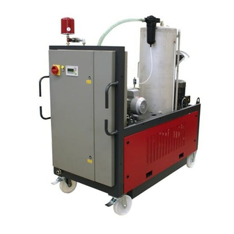
FluidAqua Mobil
FAM 25/45/60/75/95
Operating and maintenance instructions
E
n
g
l
i
s
h
(
t
r
a
n
s
l
a
t
i
o
n
o
f
o
E
n
g
l
i
s
h
(
t
r
a
n
s
l
a
t
i
o
n
o
f
o
Document No.: 3402054f
(Valid from PLC program version V 1.45)
r
i
g
i
n
a
l
i
n
s
t
r
u
c
t
i
o
n
s
)
r
i
g
i
n
a
l
i
n
s
t
r
u
c
t
i
o
n
s
)
Advertisement
Table of Contents

Related Manuals for Hydac FluidAqua Mobil FAM 25


Summary of Contents for Hydac FluidAqua Mobil FAM 25
- Page 1 FluidAqua Mobil FAM 25/45/60/75/95 Operating and maintenance instructions Document No.: 3402054f (Valid from PLC program version V 1.45)
-
Page 2: Imprint
Court of Registration: Saarbrücken, HRB 17216 Executive director: Mathias Dieter, Dipl.Kfm. Wolfgang Haering Documentation Representative Mr. Günter Harge c/o HYDAC International GmbH, Industriegebiet, 66280 Sulzbach / Saar Telephone: ++49 (0)6897 509 1511 Fax: ++49 (0)6897 509 1394 E-Mail: guenter.harge@hydac.com © HYDAC FILTER SYSTEMS GMBH All rights reserved. -
Page 3: Table Of Contents
Contents Contents Imprint ........................2 Documentation Representative................2 Contents........................3 Preface ........................8 Technical Support....................9 Modifications to the Product ...................9 Warranty .........................9 Using the Documentation ..................10 General Safety Information..................11 Hazard symbols ....................11 Signal words and their meaning in the safety information and instructions ..12 Structure of the safety information and instructions.......... - Page 4 Contents FAM 60-95 with OFU – stationary (FAM-xx-1-x-x-26-…)........29 FAM 60-95 with OFU – mobile (FAM-xx-x-x-x-26-…)........... 30 FAM 60-95 with MRF – stationary (FAM-xx-1-x-x-40-…) ........31 FAM 60-95 with MRF – mobile (FAM-xx-2-x-x-40-…) .......... 32 Hydraulic diagram ....................33 Technical Specifications ..................35 Function description ....................36 Power unit with water ring vacuum pump .............
- Page 5 Contents T (Temperature) ....................66 Selection Contamination (CONT.)..............67 Operating Mode - OM ................... 68 Operating modes - Brief overview / Brief description ........69 Operating mode - Dewater to / Filter to ..............72 Operating mode - MANU ..................73 Operating mode - MANU – OPERATOR (MANU1)........... 73 Operating mode - MANU - OPERATOR (MANU2) ...........
- Page 6 Contents Replacing the filter element on the fluid filter............103 Filter housing 2600 (FAM-xx-x-x-x-26-…) – Changing filter element ....104 OLF-5 Toploader (FAM-xx-x-x-x-10-…) – Changing filter element ....108 MRF filter housing (FAM-xx-x-x-x-40-…) – Changing filter element ....112 Checking the vacuum column level sensor ............114 Switching Status - Level Sensor Vacuum Column/PLC ........
- Page 7 Contents 36. Water tank of the water ring vacuum pump is overfilled -> Drain off water ........................148 37. Saturation oil >= 90%. Measurement with CS 1xxx not possible!....149 Replacement Parts and Accessories List ............150 Storing the unit / taking it out of operation............152 Disposing of the unit....................152 Technical Data ......................153 Type label ......................154...
-
Page 8: Preface
If you discover errors while reading the documentation or have additional comments or suggestions, contact us at: HYDAC FILTER SYSTEMS GMBH Technische Dokumentation Postfach 12 51 66273 Sulzbach / Saar Germany We look forward to receiving your input. -
Page 9: Technical Support
When making modifications or performing repair work to components affecting the safety of the product, the product may not be put back into operation until it has been examined and released by a HYDAC representative. Please notify us immediately of any modifications made to the product whether by you or a third party. -
Page 10: Using The Documentation
Preface Using the Documentation Note that the method described for locating specific information does not release you from your responsibility of carefully reading these instructions prior to starting the unit up for the first time and at regular intervals in the future. What do I want to know? I determine which topic I am looking for. -
Page 11: General Safety Information
General Safety Information General Safety Information The unit was built according to the statutory provisions valid at the time of delivery and satisfies current safety requirements. Any residual hazards are indicated by safety information and instructions and are described in the operating instructions. Observe all safety and warning instructions attached to the unit. -
Page 12: Signal Words And Their Meaning In The Safety Information And Instructions
General Safety Information Risk of burns due to hot surfaces Substances that are health hazards or irritants Signal words and their meaning in the safety information and instructions DANGER DANGER indicates a hazard with a high risk and which will lead to death or serious injury if not avoided. -
Page 13: Structure Of The Safety Information And Instructions
General Safety Information Structure of the safety information and instructions All warning instructions in this manual are highlighted with pictograms and signal words. The pictogram and the signal word indicate the severity of the danger. Warning instructions listed before an activity are laid out as follows: SIGNAL WORD Type and source of danger HAZARD SYMBOL... -
Page 14: Proper/Designated Use
General Safety Information Proper/Designated Use Use the unit only for the application described in the following. The FAM is for dewatering, filtering and degassing hydraulic and lubricating oils. In addition, it removes free water, emulsified water and a large percentage of the water found in solution. - Page 15 General Safety Information … … (FPM, ® Viton UPE/ … … (FPM, ® Viton FAM 25/45/60/75/95 Page 15/160 en(us) BEWA FAM25-95 3402054f en(us) 2013-06-13 2013-06-13...
-
Page 16: Improper Use Or Use Deviating From Intended Use
Any use extending beyond or deviating therefrom shall not be considered intended use. HYDAC Filter Systems GmbH will assume no liability for any damage resulting from such use. The user alone, shall assume any and all associated risk Improper use may result in hazards and/or will damage the unit. -
Page 17: Qualifications Of Personnel / Target Group
General Safety Information Qualifications of personnel / target group Persons who work on the power unit must be aware of the associated hazards when using the power unit. Auxiliary and specialist personnel must have read and understood the operating instructions, in particular the safety information and instructions, and applicable regulations before beginning work. -
Page 18: Wear Suitable Clothing
General Safety Information Wear suitable clothing Loosely worn clothing increases the danger of getting caught or wound up in rotating parts and the danger of getting snagged on projecting parts. You can be severely injured or killed. Wear close-fitting clothing. Do not wear any rings, chains or any other jewelry. -
Page 19: Modifications To The Fluidaqua Mobil
Do not make any modifications (design modifications, extensions) to the FluidAqua Mobil without the prior consent of the manufacturer. Any modifications require written permission from HYDAC Filter Systems GmbH Immediately replace any machine components which are not in perfect condition. -
Page 20: Transporting The Fam
Transporting the FAM Transporting the FAM Evacuate the FAM completely before transporting it and close the inlets and outlets. Wind the suction and pressure hose and the connection cable around the holders provided for this purpose and fasten them in place. Transporting the FAM - mobile FAM (FAM-xx-2-…) CAUTION High empty weight... -
Page 21: Crane
Transporting the FAM Crane NOTICE Unsuitable lifting accessories The FAM will be damaged / Components will be damaged / destroyed ► Use only suitable lifting accessories to raise or lash the FAM. ► Take care to ensure that the lifting accessories does not cause any pressures to be brought to bear against the components on the FAM. -
Page 22: Checking The Scope Of Delivery
Checking the scope of delivery Checking the scope of delivery Upon receiving the FAM check it for any damage in transit. The FAM may not be set up and installed unless it is in perfect order. Any damage in transit is to be reported to the forwarding agent or the department in charge immediately;... -
Page 23: Fam Description
FAM Description FAM Description The FluidAqua Mobil was developed for the dewatering, filtration and degassing of hydraulic and lubricating oils. It removes free water, emulsified water and a large percentage of the water to be found in solution. The integrated fluid filter ensures an efficient separation of solid particles. -
Page 24: Fam Version - Mobile (Fam-Xx-2
FAM Description FAM Version - mobile (FAM-xx-2-…) Compared to the stationary version of the unit, the mobile version features: 2 casters, 2 bock rolls Suction hose, L= 5 m Return hose , L= 5 m Connector cable 10m with CEE plug Hose retainer FAM 25/45/60/75/95 Page 24/160... -
Page 25: System Components Fam 25-45
FAM Description System Components FAM 25-45 INLET OUTLET Suction filters AquaSensor AS 1000 Filling pump Vacuum column Heater (optional) Evacuation pump Fluid filter for the separation of solid particles Air filter and dryer Vacuum gauge to set the required pressure in the vacuum column Vacuum pump Oil mist separator Pump for CS 1000 (only with option that includes ContaminationSensor) -
Page 26: System Components Fam 60-95
FAM Description System Components FAM 60-95 INLET OUTLET Suction filters AquaSensor AS1000 Filling pump Vacuum column Heater (optional) Evacuation pump Fluid filter for the separation of solid particles Air filter and dryer Vacuum gauge to set the required pressure in the vacuum column Vacuum pump Oil mist separator Pump for CS 1000 (only with option that includes ContaminationSensor) -
Page 27: Dimensions
Dimensions Dimensions The different versions of the FAM series have the following illustrated dimensions. FAM 25-45 – stationary (FAM-xx-1-…) *) working space required (all specifications in mm) FAM 25/45/60/75/95 Page 27/160 en(us) BEWA FAM25-95 3402054f en(us) 2013-06-13 2013-06-13... -
Page 28: Fam 25-45 - Mobile (Fam-Xx-2
Dimensions FAM 25-45 – mobile (FAM-xx-2-…) *) working space required (all specifications in mm) FAM 25/45/60/75/95 Page 28/160 en(us) BEWA FAM25-95 3402054f en(us) 2013-06-13 2013-06-13... -
Page 29: Fam 60-95 With Ofu - Stationary (Fam-Xx-1-X-X-26
Dimensions FAM 60-95 with OFU – stationary (FAM-xx-1-x-x-26-…) *) working space required (all specifications in mm) FAM 25/45/60/75/95 Page 29/160 en(us) BEWA FAM25-95 3402054f en(us) 2013-06-13 2013-06-13... -
Page 30: Fam 60-95 With Ofu - Mobile (Fam-Xx-X-X-X-26
Dimensions FAM 60-95 with OFU – mobile (FAM-xx-x-x-x-26-…) *) working space required (all specifications in mm) FAM 25/45/60/75/95 Page 30/160 en(us) BEWA FAM25-95 3402054f en(us) 2013-06-13 2013-06-13... -
Page 31: Fam 60-95 With Mrf - Stationary (Fam-Xx-1-X-X-40
Dimensions FAM 60-95 with MRF – stationary (FAM-xx-1-x-x-40-…) *) working space required (all specifications in mm) FAM 25/45/60/75/95 Page 31/160 en(us) BEWA FAM25-95 3402054f en(us) 2013-06-13 2013-06-13... -
Page 32: Fam 60-95 With Mrf - Mobile (Fam-Xx-2-X-X-40
Dimensions FAM 60-95 with MRF – mobile (FAM-xx-2-x-x-40-…) *) working space required (all specifications in mm) FAM 25/45/60/75/95 Page 32/160 en(us) BEWA FAM25-95 3402054f en(us) 2013-06-13 2013-06-13... -
Page 33: Hydraulic Diagram
Hydraulic diagram Hydraulic diagram Option: ContaminationSensor CS1000 [03] [02] [01] Suction filters AquaSensor AS1000 Filling pump Check valve Vacuum column Heater (optional) Evacuation pump Check valve (FAM 25-45 only) Fluid filter for the separation of solid particles Differential pressure switch for filter monitoring Fluid filter drainage Check valve (FAM 60-95 only) Air filter and dryer... - Page 34 Hydraulic diagram Differential pressure relief valve CS1000 (optional) Oil pan leakage indicator Vacuum column drainage Return valve FAM 25/45/60/75/95 Page 34/160 en(us) BEWA FAM25-95 3402054f en(us) 2013-06-13 2013-06-13...
-
Page 35: Technical Specifications
Technical Specifications Technical Specifications The FAM is able to dewater authorized fluids down to a water content of less than 100 ppm and transformer oils down to less than 10 ppm. As an approximate guideline, the dimensioning of the FluidAqua Mobil can be defined in accordance with the tank volume. -
Page 36: Function Description
Function description Function description Option: ContaminationSensor CS1000 [03] [02] [01] Connect up the power unit in bypass flow with the tank that is to be cleaned. After the unit is switched on, the filling pump (3) begins to convey the fluid from the tank through the suction filter (1) into the vacuum column (5). -
Page 37: Power Unit With Water Ring Vacuum Pump
Function description All of the functions on the SIMATIC panel can be selected, except for the regulation of the vacuum pressure. The electrical control of the Siemens S7 series monitors the functioning of the unit. Malfunction and error messages are displayed in plain text in the correspondingly available national language. -
Page 38: Possible Applications Of The Fam
Possible Applications of the FAM Possible Applications of the FAM Cleaning in Bypass Flow The FAM is connected with suction and pressure lines to the tank and cleans the medium to be found in it in constant bypass flow. Purifying and transferring by pumping The FAM is connected to the contaminated oil tank with the suction hose and pumps the fluid into the tank for the purified oil while cleaning it at the same time. -
Page 39: Fam Set-Up And Connection
FAM Set-up and Connection FAM Set-up and Connection CAUTION Rotary vane vacuum pump Hazardous to health ► Always make sure there is sufficient ventilation in the surrounding area of the unit. Air coming out of the rotary vane vacuum pump can contain particles of vacuum pump oil and/or the fluid. -
Page 40: Connection Overview
FAM Set-up and Connection Connection overview The stationary and mobile FAM versions have different scopes of delivery. The stationary FAM has positions 1-4, while the mobile FAM has positions 5-8. Item FAM 25 FAM 45 FAM 60 FAM 75 FAM 95 42L / M52x2* 42L / M52x2* 42L / M52x2*... -
Page 41: Notes On Pipes And Hoses
FAM Set-up and Connection Notes on pipes and hoses NOTICE Non-permitted pressure at the inlet IN / outlet OUT Risk of malfunctions ► Determine the pressure to be anticipated at the inlet / outlet with the prescribed values. Make sure that the cross-section of the connected hoses/piping is at least as large as the cross-section of the inlet/outlet port sizes. - Page 42 FAM Set-up and Connection The pressure differential in a hydraulic line ( ) depends on the following: (line) Flow rate Kinematic viscosity Pipe dimensions fluid density The pressure loss in straight pipes ( ) can be calculated as follows: (line) ∆p ~ 6,8 * L / d * Q * V * D...
-
Page 43: Connecting The Inlet (In)
FAM Set-up and Connection Connecting the inlet (IN) The suction pressure at the FAM inlet must be in the range of -0.2 … 1 bar. Use a negative pressure-resistant, flexible hose or a pipe for the suction-side connection. Make sure that the cross-section of the connected hoses/piping is at least as large as the cross-section of the inlet/outlet port sizes. -
Page 44: Preparing Vacuum Pump For Operation
FAM Set-up and Connection Preparing vacuum pump for operation Different vacuum pumps are installed depending on the FAM version and they are described as follows: Water ring vacuum pump -> Details from page 45 FAM-xx-x-x-x-xx-W/WA-x … Rotary vane vacuum pump ->... -
Page 45: Water Ring Vacuum Pump Preparation (Fam-Xx-X-X-X-Xx-W/Wa-X
FAM Set-up and Connection Water ring vacuum pump preparation (FAM-xx-x-x-x-xx-W/WA-x …) NOTICE Operation without water The water ring vacuum pump will be destroyed ► The water ring vacuum pump requires water as its operating medium. ► Check the water level before star-up, topping up the water if necessary. ►... - Page 46 FAM Set-up and Connection Automatic water feed (optional): If the FAM is equipped with an automatic water supply for the water ring vacuum pump, connect the water supply hose according to national and generally applicable regulations. Use a pipe separator if installing on a drinking water line. The port is constructed with 1"...
-
Page 47: Rotary Vane Vacuum Pump Preparation (Fam-Xx-X-X-X-Xx-R-X
Synthetic vacuum pump oil in accordance with DIN 51506, Group VDL, ISO VG100 must be used for topping up. The vacuum pump oil can be ordered from HYDAC: Description Part no.: Vacuum pump oil VE101... -
Page 48: Filling The Rotary Vane Vacuum Pump At The Fam 25
FAM Set-up and Connection Filling the rotary vane vacuum pump at the FAM 25 Remove the safety screw for the plug at the level switch (1). Remove the plug (2) for the level switch. Unscrew the level switch (3) from the vacuum pump. -
Page 49: Electrical Connection Of The Fam
FAM Set-up and Connection Electrical Connection of the FAM DANGER Exposed electrical components in the switch cabinet Danger of fatal injury due to electric shock ► Any work involving the electrical system may only be done by a properly trained, certified electrician. -
Page 50: Checking Direction Of Rotation
FAM Set-up and Connection Checking direction of rotation Check the direction of rotation of the motor by switching it on briefly (jog mode). The FAM requires a clockwise rotating field at the connecting socket. NOTICE Incorrect phase sequence / rotation direction of the motor The pumps will be destroyed. -
Page 51: Operating Elements On The Fam
Operating Elements on the FAM Operating Elements on the FAM The following operating elements are to be found on the FAM: Item Description Main switch with E-STOP function Alarm signal lamp (yellow) Control panel (for details see page 58) Vacuum gauge to set the pressure in the vacuum column. FAM 25/45/60/75/95 Page 51/160 en(us) -
Page 52: Starting Up The Fam
Starting up the FAM Starting up the FAM NOTICE Connection IN / OUT closed The FAM will be destroyed ► Check to be sure that all of the locking fixtures at the inlet / outlet are in "open" position each time before start-up. FAM 25/45/60/75/95 Page 52/160 en(us) -
Page 53: Switching On The Fam
Starting up the FAM Switching on the FAM Move main switch to the "ON" position and wait until the "Fault" lamp lights up briefly (lamp test) and the following start screen will appear after 30 seconds. The most recently selected operating mode will be shown in the display. Select an operating mode with heater in the presence of viscosities ≥350 mm²/s. -
Page 54: Setting The Pressure In The Vacuum Column
Starting up the FAM Setting the pressure in the vacuum column For the current pressure in the vacuum column, consult the control panel. Rel. moisture: Nominal:30% Actual:33% Temp 22°C Pressure: 970 mbar(abs ) Ready for operation. Please press Start START STOP MENU1 RESET... - Page 55 Starting up the FAM With a lower pressure (such as 250 mbar), you achieve an lower residual water content. With a higher pressure (such as 500 mbar), you achieve a faster dewatering, especially with free water. By closing the vacuum gauge (D) you reduce the absolute pressure and the required air-flow rate for dewatering the fluid.
-
Page 56: Bleeding The Filter Housing Fluid Filter
Starting up the FAM Bleeding the filter housing fluid filter WARNING Hot fluid Danger of burns ► Note that hot fluid may exit during bleeding. NOTICE Air in the fluid filter The filter element is not utilized completely ► Bleed the fluid filter after each shut-down / filter element replacement. The fluid filter is to be bled through the bleed port (A) in the cover until fluid emerges. -
Page 57: Shutting Off The Fam
Shutting off the FAM Shutting off the FAM Rel. moisture: Nominal:30% Actual:33% Temp 22°C Pressure: 970 mbar(abs ) Automatic mode MENU1 STOP F2 = STOP F4 = back to "MENU1" Press the "STOP" key. The power unit starts the after-run phase. ... -
Page 58: Control Panel Basic (Simatic Panel)
Control Panel Basic (SIMATIC PANEL) Control Panel Basic (SIMATIC PANEL) HELP SHIFT ENTER All functions are input and controlled using this control panel. Due to the size of the display it is necessary to radically shorten the texts relating to the operating modes and the functions. -
Page 59: Overview Of Operating Modes And Abbreviations
Control Panel Basic (SIMATIC PANEL) Overview of operating modes and abbreviations Abbreviation Description Menu 1: Operating mode Hand Manual menu Menu 2: an operating-hours counter, and Config Configuration menu Buttons: RH + T Relative Humidity + Temperature Temperature (only with heater option) Cont. -
Page 60: Overview Of Menu Structure
Control Panel Basic (SIMATIC PANEL) Overview of menu structure Menu 1 Cont. ISO, SAE, NAS OM - Operating Mode DW+FT DWT+ DWT + FTB EW+H+FT DWT + H + FT DWT + H + FTB FT+H EW+FTB EW+H+FTB FTT+H DW+FT MANU OPERATOR MANU 1... - Page 61 Control Panel Basic (SIMATIC PANEL) an operating-hours counter, and Configuration FAM 25/45/60/75/95 Page 61/160 en(us) BEWA FAM25-95 3402054f en(us) 2013-06-13 2013-06-13...
-
Page 62: Changing / Entering Values
Control Panel Basic (SIMATIC PANEL) Changing / entering values Meas. values: MENU1 Cont. -> Menu keys MANU MENU2 -> Function key assignment -> Function keys The menu keys illustrated can be selected with the keys or by means SHIFT of the key combination , which is marked by framing made up of a line of dashes. -
Page 63: Menu1
Control Panel Basic (SIMATIC PANEL) Menu 1 MENU1 Meas. values: MENU1 Cont. -> Menu keys MANU MENU2 -> Function key assignment -> Function keys The menu keys shown can be selected with the keys . The selected menu key is marked by a dashed line around its circumference. Pressing the key switches over to the selected menu. -
Page 64: Start Screen
Control Panel Basic (SIMATIC PANEL) Start screen The selected operating mode is shown in the upper line, the middle line shows the current operating status, and the key assignment is displayed in the lower line. You see this start screen only after switching on the power unit using the main switch. -
Page 65: Rh+P (Relative Humidity + Pressure)
Control Panel Basic (SIMATIC PANEL) RH+P (Relative Humidity + Pressure) Start screen -> MENU1 -> RF-D Rel. moisture: Nominal:30% Actual:33% Temp 22°C Pressure: 970 mbar(abs ) Ready for operation. Please press Start START STOP MENU1 RESET START Start FAM Display in operating status "Ready for operation" and with the error message "Water content ≥... -
Page 66: T (Temperature)
Control Panel Basic (SIMATIC PANEL) T (Temperature) MENU1 -> T Heater: Hysteresis: 5°C Temperature: Nominal: 55°C Actual: Ready for operation. Please press Start START STOP MENU1 RESET START Start FAM Display in operating status "Ready for operation" and with the error message "Water content ≥... -
Page 67: Selection Contamination (Cont.)
Control Panel Basic (SIMATIC PANEL) Selection Contamination (CONT.) MENU1 -> Cont. -> ISO (example, can also be SAE or NAS depending on sensor) 4µ 6µ 14µ tgt: act: 4µ 6µ 14µ Ready for operation. Please press Start START STOP RESET MENU1 START Start FAM... -
Page 68: Operating Mode - Om
Control Panel Basic (SIMATIC PANEL) Operating Mode - OM MENU1 -> OM Operating mode: Dewatering + Filtration DWT+ DW+FT NEXT DW+FT Dewatering and Filtration DWT+ Dewatering up to and Filtration Filtration NEXT Other operating modes Only operating modes that can be selected are displayed. A change of operating mode is possible at any time during automatic operation. -
Page 69: Operating Modes - Brief Overview / Brief Description
Control Panel Basic (SIMATIC PANEL) Operating modes - Brief overview / Brief description The following offers a brief description of the operating modes: Operating Description modes: DW+FT = Dewatering The fluid will be simultaneously dewatered and and Filtration filtered. DWT+ = Dewatering The fluid will be simultaneously dewatered and up to and... - Page 70 Control Panel Basic (SIMATIC PANEL) The FAM operates until both specified nominal values have been reached (see page 65 / 67). Afterwards, the FAM switches off. Now the recurrent inspection interval starts (time until the FAM switches on again, see page 79). After this has run through, the FAM switches on automatically once again and runs for at least 2 minutes.
- Page 71 Control Panel Basic (SIMATIC PANEL) FTT+H = Filter to + The fluid will be simultaneously filtered and Heat heated up to the prescribed temperature (see page 66). Vacuum pump remains switched off. The FAM operates until a specified cleanliness code has been reached (see page 67). Then the FAM switches off.
-
Page 72: Operating Mode - Dewater To / Filter To
Control Panel Basic (SIMATIC PANEL) Operating mode - Dewater to / Filter to The operating mode "Filter to" is possible only up to a relative humidity of 90%. The CS is switched off in situations involving >90% or unmanaged water. The following message is output when the contamination menu is selected: "Oil saturation >90%. -
Page 73: Operating Mode - Manu
Selection Manual oper OPERA- MENU1 SERVICE OPERATOR Manual operation for operator SERVICE Manual operation for HYDAC Service (password-protected) MENU1 Back to MENU1 Operating mode - MANU – OPERATOR (MANU1) MENU1 -> MANUAL -> Operator Manual 1 Manual- operation Exit NEXT = return to the screen "Selection manual operation"... -
Page 74: Operating Mode - Manu - Operator (Manu2)
Control Panel Basic (SIMATIC PANEL) Operating mode - MANU - OPERATOR (MANU2) MENU1 -> MANUAL -> Operator -> Continue Manual 2 Exit NEXT = back to "Manual1" Menu Switching vacuum pump on/off Switching return valve on/off Switching off the water drainage valve (present only with water ring vacuum pump) Operating mode - MANU - OPERATOR (MANU3) MENU1 ->... -
Page 75: Operating Mode - Manu - Operator (Manu4)
Control Panel Basic (SIMATIC PANEL) Operating mode - MANU - OPERATOR (MANU4) MENU1 -> MANUAL -> Operator -> Continue -> Continue -> Continue Manual 4 Exit = back to "Manual3" Menu Recirculating pump FAM 25/45/60/75/95 Page 75/160 en(us) BEWA FAM25-95 3402054f en(us) 2013-06-13 2013-06-13... -
Page 76: Operating Mode - Settings (Set)
Control Panel Basic (SIMATIC PANEL) Operating mode - SETTINGS (SET) MENU1 -> Settings Language selected: ENGLISH Select UNITS language MENU1 Select = Press the F1 key repeatedly until the desired language language appears. UNITS = Switch over to Units menu MENU1 = Switch to MENU1 Set units... -
Page 77: Set Temperature
Control Panel Basic (SIMATIC PANEL) Set temperature MENU1 -> Settings -> Units -> Temperature Temperature °C °F back °C Temperature display in °C °F Temperature display in °F back Back to Units menu Set pressure MENU1 -> Settings -> Units -> Pressure Pressure mbar back... -
Page 78: Menu2
Times for the recurrent inspection interval for the "Cleaning until" VALS and/or "Dewatering to" operating mode Display operating hours meter CONFIG. = FAM Configuration – Access password-protected (For HYDAC Service only) MENU1 Switch to MENU1 FAM 25/45/60/75/95 Page 78/160 en(us) -
Page 79: Set (Repeat Testing Interval) Times
Control Panel Basic (SIMATIC PANEL) Set (repeat testing interval) times Repeat testing interval: Intervals nominal minutes 0 elapsed minutes MENU2 Display : TRG MIN: Inspection repeating interval: Is the time after which the FAM switches on again after an automatic switch-off in the operating mode "Dewater to"... -
Page 80: Performing Maintenance
Performing Maintenance Performing Maintenance Maintenance intervals The inspection and maintenance works listed here are necessary conditions for ensuring both long service life and error-free operation of the FAM. In addition, you will find further information in the operating manuals published by the manufacturers of the components which are supplied with the FAM. - Page 81 Performing Maintenance Cleaning the condensation cooler Back-flush water filter combination (only for version with automatic water intake) Rotary vane vacuum pump Checking the oil level Replace oil, oil filter and air de-oiling element Check and clean the ventilator hood Emptying/Filling Pump Check and clean the ventilator hood Fluid filter Changing the filter element...
- Page 82 Performing Maintenance heater and compare values with type label (applies only to versions with integrated heater) Function Test Check and clean the level sensor in the vacuum column. Testing the oil pan float switch Completely replace all of the hoses after 5 years. The pictures and illustrations in the descriptions are examples.
-
Page 83: Function Testing Of The Fault Indicator Lamp
The air filter replacement has been completed. Checking the AquaSensor Check the AquaSensor annually with the calibration and adjustment set (HYDAC p/no. 3122629). Replace the AquaSensor if it exhibits great deviations. The part-no. can be found in the spare parts list. -
Page 84: Recognise / Find Suction Line Filter Type
Performing Maintenance Recognise / find suction line filter type The suction line filter series has been optimized. As a result there are different ways in which to replace the filter element. Both methods are described below: Old suction line filter - Cleaning / changing the filter element Switch off the unit at the main switch. -
Page 85: New" Suction Line Filter - Cleaning / Changing The Filter Element
Performing Maintenance containing a slip additive (MoS2) (Hydac part-no.: 3066287). Screw the filter bowl to the filter retainer. Screw the union nut [B] hand-tight only. The suction line filter is ready for operation. Check the suction line filter during operation for any untight spots. - Page 86 Performing Maintenance To change the filter, proceed as follows: Switch off the unit at the main switch. Close the shut-off valve to the inlet. Unscrew the filter bowl (4.2) with a 27 mm wrench. Return the fluid from the filter bowl (4.2) to the tank. Pull the filter element (1.1) downwards out of the filter head (4.1), wash it out and clean it using compressed air, or dispose of the filter element (1.1) in an environmentally friendly manner.
-
Page 87: Water Ring Vacuum Pump (Fam-Xx-X-X-Xx-W/Wa
Performing Maintenance Water ring vacuum pump (FAM-xx-x-x-xx-W/WA-...) maintenance Check/Clean the level switch To check or clean the level switch, proceed as follows: Remove the covering tin (1) of the vacuum pump. Unscrew the four fastening screws of the level switch. Remove the level switch (2) from the vacuum pump in an upward direction. -
Page 88: Replacing The Water Filter
Performing Maintenance Replacing the Water Filter Rinse and clean the vacuum pump before changing the water filter. Remove the covering tin of the vacuum pump. Remove the protection safety fence. Replace the water filter. Dispose of the used water filters in an environmentally-friendly manner. -
Page 89: Cleaning The Cooling Fins
Performing Maintenance Cleaning the Cooling Fins To clean the cooling fins, proceed as follows: Remove the covering tin. Remove the protection safety fence. Use compressed air to clean the cooling fins of the water cooler. Perform the assembly in reversed order of sequence. - Page 90 Performing Maintenance Remove the five attachment screws on the side cover plate of the water cooler. Remove the cover plate of the water cooler. Open the strap of the feed line hose [1]. Pull the feed line hose off the support. Open the strap of the return line and pull the return line off the support/T-piece.
- Page 91 Performing Maintenance Remove the cover plate (1), the level switch (2) and the bung plug (3) from the filling opening. Fill the pump with hot water (60-65°C) through the filling opening or the opening for the level switch until the water emerges from the filling opening.
- Page 92 Performing Maintenance the level switch opening and the filling opening. Take care to ensure that the drain ball valve is open for this purpose. Close the drain ball valve. Fill the vacuum pump until water emerges from the filling opening. Screw in the bung plugs.
-
Page 93: Cleaning The Condensation Cooler Of The Vacuum Pump
Performing Maintenance Cleaning the condensation cooler of the vacuum pump To perform these tasks, you will need the following tools and equipment: Compressed air VacuCleaner Bucket (~ 25 liters) or comparable vessel Hot water 60-65°C O-rings (1x 67.95 x 2.62, 1x 72.62 x 3.53) ... - Page 94 Performing Maintenance Carefully remove the cooler insert by rotating it. Apply compressed air to free the insert of coarse contamination. Place the insert into a cleaning bath with hot water (temperature 60–65°C) and 5% VacuCleaner for around 45 minutes. Example: 10 l water + 0.5 l VacuCleaner. Afterwards, rinse out the insert with clear water.
-
Page 95: Water Filter Combination (Fam-Xx-X-X-Xx-Wa
Performing Maintenance Water filter combination (FAM-xx-x-x-xx-WA-...) maintenance Perform maintenance on the optional water filter combination at regular intervals as described in the following. Back-Flush Water Filter Combination In order to back-flush the water filter, proceed as follows: You will require the following: ... -
Page 96: Checking / Setting The Downstream Pressure
Performing Maintenance Checking / setting the downstream pressure Downstream pressure is the term used for the pressure after the water filter combination. Reduce the pressure to prevent strong turbulence in the vacuum pump tank when the operating pressure is high. The downstream pressure at the filter combination is set ex-works to 5 bar. -
Page 97: Maintenance Of Rotary Vane Vacuum Pump (Fam-25-X-X-Xx-R
Performing Maintenance Maintenance of rotary vane vacuum pump (FAM-25-x-x-xx-R-…) Item Name Oil filler neck Oil drain Oil sight glass Oil separator Suction port connection Gas outlet Safety screw on the plug Plug for the level sensor Level switch in the vacuum pump The following descriptions are in reference to these positions. -
Page 98: Replacing Oil And Oil Filter (Fam 25)
Performing Maintenance Replacing oil and oil filter (FAM 25) The first oil change must take place after 100 operating hours. Afterwards, the interval increases to ~ 3000 hours or twice per year. The vacuum pump must be at operating state temperature when the oil is changed: Put the FAM into operation for 10 minutes. -
Page 99: Replacing The Air De-Oiling Element (Fam 25)
Performing Maintenance Replacing the air de-oiling element (FAM 25) Oil mist or increased electricity consumption by the drive engine (response of the engine protection switch) are signs of a soiled air de-oiling element. To replace the air de-oiling element, proceed as follows: Remove the ventilation cover (i) from the oil separator (g). -
Page 100: Rotary Vane Vacuum Pump (Fam 45/60/75/95-Xx-X-X-Xx-R
Performing Maintenance Rotary vane vacuum pump (FAM 45/60/75/95-xx-x-x-xx-R-…) Item Name Oil separator Inlet flange Oil sight glass Screw plug Screw plug Exhaust valve Rotor vane Rotor Air de-oiling element Exhaust cover Oil filter Demister Oil sump Service cover Leaf spring The following descriptions are in reference to these positions. -
Page 101: Changing Vacuum Pump Oil And Oil Filter (Fam 45-95)
Performing Maintenance Changing vacuum pump oil and oil filter (FAM 45-95) The first oil change must take place after 100 operating hours. Afterwards, the interval increases to ~ 3000 hours or twice per year. The vacuum pump must be at operating state temperature when the oil is changed. Switch on the unit and let it run for at least 10 minutes, then switch it off at the main switch. -
Page 102: Replacing The Air De-Oiling Element Of The Vacuum Pump (Fam 45-95)
Performing Maintenance Replacing the air de-oiling element of the vacuum pump (FAM 45-95) Oil mist or increased electricity consumption by the drive engine (response of the engine protection switch) are signs of a soiled air de-oiling element. To replace the air de-oiling element, proceed as follows: Remove the 4 attachment screws of the ventilation cover (10). -
Page 103: Replacing The Filter Element On The Fluid Filter
Performing Maintenance Replacing the filter element on the fluid filter WARNING Hydraulic system is under pressure Danger of bodily injury ► The hydraulic system must be depressurized before performing any work on the hydraulic system. ► Switch off the FAM before replacing the filter element. -
Page 104: Filter Housing 2600 (Fam-Xx-X-X-X-26
Performing Maintenance Filter housing 2600 (FAM-xx-x-x-x-26-…) – Changing filter element Switch off the unit at the main switch. Depressurize the filter housing. Remove the air bleed plug (1) in the filter cover for this purpose. The residual oil is drained through the drain ball valve (2) into a suitable container. - Page 105 Performing Maintenance Clean any coarse dirt from the inside of the filter housing as well as from the sealing surfaces on the housing and the cover. For easier installation of the filter element, wet the O-ring on the filter element with the operating medium.
- Page 106 Performing Maintenance Put the cover on. Observe correct placement of the O-ring on the cover while doing so. It must not be damaged. 10. Fold the 4 screws upward and, working cross-wise and clockwise, screw them in with uniform tightness. 11.
- Page 107 Performing Maintenance 15. The filter element change on the fluid filter is now complete. FAM 25/45/60/75/95 Page 107/160 en(us) BEWA FAM25-95 3402054f en(us) 2013-06-13 2013-06-13...
-
Page 108: Toploader (Fam-Xx-X-X-X-10
Performing Maintenance OLF-5 Toploader (FAM-xx-x-x-x-10-…) – Changing filter element Change the filter element as soon as the visual differential pressure gauge is red. The bayonet mount on the filter element makes changing the filter element easier. Rotate the filter element 90° clockwise or counterclockwise to separate it from the element receptacle. - Page 109 Performing Maintenance Carefully pull off the filter housing cover. Turn it slightly clockwise. This ensures that the filter element remains locked on the cover. Turn counterclockwise to detach the element from the cover and the dirt catch tray from the element. Remove the dirt catch tray.
- Page 110 Performing Maintenance Attach the dirt catch tray to the lower end of the filter element and lock it in place by turning it 90° counterclockwise. 10. Place the filter element with the cover and dirt catching tray in the filter housing. 11.
- Page 111 Performing Maintenance 14. Bleed the filter bowl through the air bleed screw (Air Bleed) in the cover. 15. The filter element change on the fluid filter is now complete. FAM 25/45/60/75/95 Page 111/160 en(us) BEWA FAM25-95 3402054f en(us) 2013-06-13 2013-06-13...
-
Page 112: Mrf Filter Housing (Fam-Xx-X-X-X-40
Performing Maintenance MRF filter housing (FAM-xx-x-x-x-40-…) – Changing filter element Switch off the unit at the main switch. Close all shut-off valves at the inlet and outlet. Depressurize the filter housing. Unscrew the air bleed screw (x) completely using a 10 mm Allen wrench. Open the drain valve on the contamination side. - Page 113 Performing Maintenance Insert the filter element holding plate [B]. Fasten on the external filter elements. The middle filter elements do not require any further fastening. Screw on all of the star grips [A] gently by hand. Clean the sealing surface on the housing. Check the O-ring on the cover for damage and replace it if necessary.
-
Page 114: Checking The Vacuum Column Level Sensor
Performing Maintenance Checking the vacuum column level sensor Proceed as follows to dismantle the vacuum column level sensor: Undo the safety screw (A) on the plug (B). Pull out the plug (B). Screw out the level sensor (C) with an SW30 open-jaw wrench. -
Page 115: Switching Status - Level Sensor Vacuum Column/Plc
Performing Maintenance Switching Status - Level Sensor Vacuum Column/PLC [01] [02] [03] Minimum Maximum Maximum E-STOP I0.3 I0.4 I0.5 I0.3 I0.4 I0.5 I0.3 I0.4 I0.5 FAM 25/45/60/75/95 Page 115/160 en(us) BEWA FAM25-95 3402054f en(us) 2013-06-13 2013-06-13... -
Page 116: Testing The Float Switch In The Oil Pan
If the unit does not switch off after the lifting of the float switch and no fault message appears, contact the HYDAC Service. FAM 25/45/60/75/95 Page 116/160 en(us) BEWA FAM25-95 3402054f en(us) 2013-06-13... -
Page 117: Oil Mist Separator Maintenance
Performing Maintenance Oil Mist Separator Maintenance Item Name Separator head Separator pot Clogging indicator Filling level display The oil mist separator is located between the vacuum column and the vacuum pump. A filter element is used to retain the oil mist and the oil in the oil mist separator and the oil is collected in the separator pot, where it is continuously suctioned off and returned to the vacuum column. -
Page 118: Replacing The Filter Element On The Oil Mist Separator
Performing Maintenance Replacing the filter element on the oil mist separator Proceed as follows to replace the filter element on the oil mist separator: Stop automatic mode. Afterwards, wait ~ 1 minute, until normal pressure (ambient pressure) has been established in the vacuum chamber. Rotate the separator pot (2) 1/8th of a turn to the left (bayonet seal) and remove from the bottom. -
Page 119: Error Messages / Troubleshooting
Error messages / troubleshooting Error messages / troubleshooting NOTICE Switch off the FAM at the main switch before opening the control cabinet door The main switch will be destroyed. ► Do not open the control cabinet door if the main switch is not in OFF position. -
Page 120: Cs+Pump Switched Off. Cs Fault. Start 10 New Attempts With Reset
Error messages / troubleshooting To switch off the error messages, press the button. If the fault indicator lamp is flashing, error messages are present. To show error messages again, switch to Menu 1 or Menu 2 and then return to the display window. -
Page 121: Flow At Fam Inlet Has Been Too Low For 5 Minutes. Check The Fam Inlet
Start the unit by pressing the F1 key. ->a. The fault is repeated. -> proceed to Step 10. ->b. The fault is not repeated. -> proceed to Step 11. Contact the HYDAC Service Department. The fault is repaired. FAM 25/45/60/75/95 Page 121/160 en(us) -
Page 122: Fam Outlet Is Blocked
Start the unit by pressing the F1 key. ->a. The fault is repeated. -> proceed to Step 10. ->b. The fault is not repeated. -> proceed to Step 11. Contact the HYDAC Service Department. The fault is repaired. FAM 25/45/60/75/95 Page 122/160 en(us) -
Page 123: Error, Float Switch Of Rotary Vane Vacuum Pump At Fill Level Min. / Fill Level Overflow
-> proceed to Step 8. Replace the level switch. -> proceed to Step 10. Replace the damaged parts -> proceed to Step 10. The PLC is defective -> contact the HYDAC Service Department. The fault is repaired. FAM 25/45/60/75/95 Page 123/160 en(us) -
Page 124: 6. Error, Float Switch Of Vacuum Column At Fill Level Max And/Or Fill Level Overflow
-> proceed to Step 8. Replace the level switch. -> proceed to Step 10. Replace the damaged parts -> proceed to Step 10. The PLC is defective -> contact the HYDAC Service Department. The failure is repaired. FAM 25/45/60/75/95 Page 124/160 en(us) -
Page 125: Error Filling By Automatic Water Supply
-> proceed to Step 12. ->b. The fault is not repeated. -> proceed to Step 14. The PLC is defective -> contact the HYDAC Service Department. Replace the cable and/or the plug. -> proceed to Step 10. The fault is repaired. -
Page 126: Error Starting Automatic Water Feed
-> proceed to Step 12. ->b. The fault is not repeated. -> proceed to Step 14. The PLC is defective -> contact the HYDAC Service Department. Replace the cable and/or the plug. -> proceed to Step 10. The fault is repaired. -
Page 127: 12. / 14. / 15. Cable Break
Error messages / troubleshooting 11. / 12. / 14. / 15. Cable break Cause: Error 11. / 12. / 14. / 15. The signal is immediately active after the lamp test (except with AS temperature: 5 s), error message flashes on the display, the FAM continues however to run. - Page 128 F1 key. ->a. The fault is repeated. -> proceed to Step 5. ->b. The fault is not repeated. -> proceed to Step 13. Contact the HYDAC Service Department. The fault is repaired. FAM 25/45/60/75/95 Page 128/160 en(us) BEWA FAM25-95 3402054f en(us) 2013-06-13...
-
Page 129: No Defined Value From Cs
Error messages / troubleshooting 16. No defined value from CS Cause: The charge pump for the CS runs for 2 minutes in Automatic mode. The CS has been reporting "no measured value from CS" for 4 minutes. The message is shown on the CS display. The FAM continues to run. -
Page 130: No Measured Value From Cs. Check For Flow
Error messages / troubleshooting 17. No measured value from CS. Check for flow Cause: The charge pump for the CS runs for 2 minutes in Automatic mode. The CS has been reporting "no measured value from CS" for 4 minutes. The message is shown on the CS display. -
Page 131: 19. / 20. / 21. / 22. Motor Protection Switch Qx Has Tripped
Error messages / troubleshooting 18. / 19. / 20. / 21. / 22. Motor protection switch Qx has tripped. Cause: The motor protection switch has tripped, due to an overload in the motor-pump group. The FAM switches off after 1.8 seconds. - Page 132 Error messages / troubleshooting ->b. The fault is not repeated. -> proceed to Step 13. Contact the HYDAC Service Department. The fault is repaired. FAM 25/45/60/75/95 Page 132/160 en(us) BEWA FAM25-95 3402054f en(us) 2013-06-13 2013-06-13...
-
Page 133: Oil Filter Contaminated -> Replace Oil Filter
->a. The test resulted in no errors. -> proceed to Step 12. ->b. The errors found were eliminated. -> proceed to Step 6. The PLC is defective -> contact the HYDAC Service Department. The fault is repaired. FAM 25/45/60/75/95 Page 133/160... -
Page 134: Oil Tank Of Rotary Vane Vacuum Pump Is Empty -> Refill Oil
Error messages / troubleshooting 24. Oil tank of rotary vane vacuum pump is empty -> refill oil Cause: The MIN switch point in the oil tank of the rotary vane vacuum pump has been reached. The message appears at once on the display. The FAM goes into the after-running phase and switches off. -
Page 135: Oil Tank Of Rotary Vane Vacuum Pump Is Too Full -> Drain Oil
Error messages / troubleshooting 25. Oil tank of rotary vane vacuum pump is too full -> drain oil Cause: The MAX switch point in the oil tank of the rotary vane vacuum pump has been reached for 10 minutes. The message appears on the display. -
Page 136: Heater Safety Thermostat Triggered
Error messages / troubleshooting 26. Heater safety thermostat triggered Cause: Thermostat trips during operating mode with heater. The FAM goes into the after-running phase and switches off. If an operating mode is selected for which no heater is switched on, then it is possible to operate the FAM. The message will however be displayed and can be reduced with ESC. - Page 137 F1 key. ->a. The fault is repeated. -> proceed to Step 13. ->b. The fault is not repeated. -> proceed to Step 21. Contact the HYDAC Service Department. The fault is repaired. FAM 25/45/60/75/95 Page 137/160 en(us)
-
Page 138: Fuse F2 Has Tripped
Error messages / troubleshooting 27. Fuse F2 has tripped Cause: The F2 fuse triggers. A message appears on the display. The FAM switches off at once. The fault indicator lamp is not flashing. Remedy: Perform the following steps: Description Message: 27. -
Page 139: Heater Fuse Has Tripped
F1 key. ->a. The fault is repeated. -> proceed to Step 14. ->b. The fault is not repeated. -> proceed to Step 15. Contact the HYDAC Service Department. The fault is repaired. FAM 25/45/60/75/95 Page 139/160 en(us) - Page 140 Error messages / troubleshooting FAM 25/45/60/75/95 Page 140/160 en(us) BEWA FAM25-95 3402054f en(us) 2013-06-13 2013-06-13...
-
Page 141: Check Phase Sequence
->a. The fault is repeated. -> proceed to Step 12. ->b. The fault is not repeated. -> proceed to Step 13. Contact the HYDAC Service Department. The fault is repaired. NOTICE Incorrect phase sequence The motors / pumps rotate in the wrong direction. - Page 142 Error messages / troubleshooting ► Using manual operation always check the direction of rotation of the motors after they have been replaced. FAM 25/45/60/75/95 Page 142/160 en(us) BEWA FAM25-95 3402054f en(us) 2013-06-13 2013-06-13...
-
Page 143: Malfunction Cs Flow Too Low
Error messages / troubleshooting 30. Malfunction CS flow too low. Cause: The charge pump for the CS runs for 2 minutes in automatic mode. The CS reports "Flow too low" or "Device error" for 4 minutes, message appears in the display of the CS. The FAM continues to run. -
Page 144: Dry-Running Evacuation Pump
Error messages / troubleshooting 32. Dry-running Evacuation Pump Cause: The evacuation pump is running and the MIN switch point in the vacuum column was reached/was not reached. The timer runs 2 minutes and the MIN switch point is not exceeded during this time. The FAM switches off at once, the message appears on the display. -
Page 145: Vacuum Column Overflow -> Drain Vacuum Column And Troubleshoot Cause
Error messages / troubleshooting 33. Vacuum column overflow -> drain vacuum column and troubleshoot cause Cause: The E-STOP MAX switch point in the vacuum column was reached. All of the pumps (except the evacuation pump) are switched off. The timer runs 4 minutes and 10 seconds. The level did not fall below the MAX switch point during the time, the FAM switches off at once, message appears on the display. -
Page 146: Oil Pan Too Full -> Drain Oil Pan And Seal Leak
Error messages / troubleshooting 34. Oil pan too full -> drain oil pan and seal leak Cause: The float switch in the tray was actuated. The message appears on the display after 1.8 seconds, and the FAM switches itself off. Remedy: Perform the following steps: Description... -
Page 147: Water Tank Of The Water Ring Vacuum Pump Empty -> Fill Up Water
Error messages / troubleshooting 35. Water tank of the water ring vacuum pump empty -> Fill up water Cause: The MIN switch point in the water ring vacuum pump has been reached. The message appears at once on the display. The FAM goes into the after-running phase and switches off. -
Page 148: Water Tank Of The Water Ring Vacuum Pump Is Overfilled -> Drain Off Water
Error messages / troubleshooting 36. Water tank of the water ring vacuum pump is overfilled -> Drain off water Cause: A signal is active, the overflow valve is opened. The level in the water ring vacuum pump did not fall below the "Overflow"... -
Page 149: Saturation Oil >= 90%. Measurement With Cs 1Xxx Not Possible
Error messages / troubleshooting 37. Saturation oil >= 90%. Measurement with CS 1xxx not possible! Cause: Error-free measurement of contamination is not possible with a water content ≥90%. The charge pump of the CS is switched off. If you selected an operating mode for which the CS controls the FAM, then the FAM will automatically jump into a similar operating mode without control by the CS. -
Page 150: Replacement Parts And Accessories List
Replacement Parts and Accessories List Replacement Parts and Accessories List Only use original spare parts and accessories to ensure safe and reliable operation of the unit. When ordering spare parts, always provide the complete designation (type, part-no., serial no., year of construction). Name Material Part no. - Page 151 Replacement Parts and Accessories List Name Material Part no. Filter element 5 µm 3405147 Filter element 10 µm 3405166 Filter element 20 µm 3405167 Fluid filter MRF Filter element 3 µm Filter element 3 µm Filter element 5 µm Filter element 5 µm Filter element 10 µm Filter element 10 µm Filter element 20 µm...
-
Page 152: Storing The Unit / Taking It Out Of Operation
Storing the unit / taking it out of operation Storing the unit / taking it out of operation Drain the unit completely, including all of its components, before putting it into storage. Pull out the power plug, and securely fasten the hoses and power cord to the FAM. Store the FAM in a clean, dry (condensation-free) space. -
Page 153: Technical Data
Technical Data Technical Data FAM 25 FAM 45 FAM 60 FAM 75 FAM 95 Flow rate at 50 Hz ~ 25 l/min ~ 45 l/min ~ 60 l/min ~ 75 l/min ~ 95 l/min Flow rate at 60 Hz ~ 114 ~ 30 l/min ~ 54 l/min ~ 72 l/min... -
Page 154: Type Label
The type label is fitted to on the rear side of the control cabinet in a readily visible position. Copy the data from the type label into the following, in order to have at hand when required. Customer Service You can reach the HYDAC Servicenter as follows: HYDAC Service GmbH Product Support, Werk 13 Friedrichsthaler Straße 15A... -
Page 155: Model Code
Model Code Model Code A - 40 - R - H - B - A - 00 Product FAM = FluidAqua Mobil Filter Size = 25 l/min = 45 l/min = 60 l/min = 75 l/min = 95 l/min Operating fluid = Mineral oil –... -
Page 156: Eu Declaration Of Conformity
Documentation Representative: Mathias Dieter, Dipl.Kfm. Wolfgang Haering Mr. Günter Harge Registered seat of company: 66280 Sulzbach / Saar - Germany c/o HYDAC International GmbH, Industriegebiet, 66280 Sulzbach / Saar Registry Court: Saarbrücken, HRB 17216 Telephone: ++49 (0) 6897 509 1511... -
Page 157: Index
Index Index Empty weight ..........154 Error 6, 119, 123, 124, 125, 126, 127, 137, 149 Error message ........6, 119 Accessories ..........7, 150 Air Filter ............150 AquaSensor... 5, 25, 26, 33, 36, 65, 80, 81, 83, Factory setting ........65, 66, 79 Auxiliary personnel ........17 Fault indicator lamp ........ - Page 158 Index 138, 139, 141, 143, 144, 145, 146, 147, 148, 149 Rotary vane vacuum pump 4, 5, 39, 44, 47, 81, Level sensor ........33, 87, 115 100, 150, 153, 155 Level switch ........97, 123, 124 Lubrication oil ..........42, 54 SAE ..........
- Page 160 HYDAC FILTER SYSTEMS GMBH Industriegebiet Postfach 1251 66280 Sulzbach/Saar 66273 Sulzbach/Saar Germany Germany Phone: +49 (0) 6897 509 01 Central Fax: +49 (0) 6897 509 846 (Technical Department) Fax: +49 (0) 6897 509 577 (Sales Department) Internet: www.hydac.com E-mail: filtersystems@hydac.com...
Need help?
Do you have a question about the FluidAqua Mobil FAM 25 and is the answer not in the manual?
Questions and answers