Table of Contents
Advertisement
Quick Links
FluidAqua Mobil
FAM 15/30/50/70 ATEX
II 2G IIB3 T4 (+10°C<Ta<40°C)
Operating and Maintenance Instructions
E
n
g
l
i
s
h
(
t
r
a
n
s
l
a
t
i
o
n
o
f
E
n
g
l
i
s
h
(
t
r
a
n
s
l
a
t
i
o
n
o
f
Documentation no.: 3193049h
o
r
i
g
i
n
a
l
i
n
s
t
r
u
c
t
i
o
n
s
)
o
r
i
g
i
n
a
l
i
n
s
t
r
u
c
t
i
o
n
s
)
Advertisement
Table of Contents

Related Manuals for Hydac FluidAqua Mobil FAM 15 ATEX


Summary of Contents for Hydac FluidAqua Mobil FAM 15 ATEX
- Page 1 FluidAqua Mobil FAM 15/30/50/70 ATEX II 2G IIB3 T4 (+10°C<Ta<40°C) Operating and Maintenance Instructions Documentation no.: 3193049h...
-
Page 2: Imprint
Court of Registration: Saarbrücken, HRB 17216 Executive director: Mathias Dieter, Dipl.Kfm. Wolfgang Haering Documentation Representative Mr. Günter Harge c/o HYDAC International GmbH, Industriegebiet, 66280 Sulzbach / Saar Telephone: ++49 (0)6897 509 1511 Fax: ++49 (0)6897 509 1394 E-mail: guenter.harge@hydac.com © HYDAC FILTER SYSTEMS GMBH All rights reserved. -
Page 3: Table Of Contents
Content Content Imprint......................2 Documentation Representative ..............2 Content ......................3 Preface......................6 Customer service..................7 Modifications to the Product ................7 Warranty ......................7 Using the Documentation ................8 Changes to the manual ................9 Preface......................10 Technical Support..................11 Modifications to the Product ..............11 Warranty ....................11 Using the Documentation ................12 Safety Information and Instructions............13 Hazard symbols..................13 Signal words and their meaning in the safety information and... - Page 4 Content FAM overview....................27 FAM components ..................29 Description of function................30 Hydraulic diagram..................31 Possible Applications of the FAM .............33 Cleaning in Bypass Flow ................33 Purifying and transferring by pumping ............33 FAM Set-up and Connection ..............34 Setting up the unit..................34 Connecting the FAM ..................35 Notes on pipes and hoses .................36 Connecting suction port (IN)..............38 Connecting the pressure port / return-flow line........39...
- Page 5 Content Performing maintenance / inspection ............61 Visual checks.....................62 Overview of maintenance intervals............63 Electrical inspection ...................66 Filling the seal chamber of the evacuation pump........67 Lubricating lock on the electrical cabinet ...........68 Replacing the filter element on the fluid filter ..........69 Checking the fault indicator lamp...............74 Clean the suction strainer.
-
Page 6: Preface
If you discover errors while reading the documentation or have suggestions or other useful information, please don’t hesitate to contact us: HYDAC FILTER SYSTEMS GMBH Technische Dokumentation Postfach 12 51... -
Page 7: Customer Service
After modification or repair work that affects the safety of the product has been carried out on components, the product may not be returned to operation until it has been checked and released by a HYDAC technician. Please notify us immediately of any modifications made to the product whether by you or a third party. -
Page 8: Using The Documentation
Preface Using the Documentation Note that the method described for locating specific information does not release you from your responsibility of carefully reading these instructions prior to starting the unit up for the first time and at regular intervals in the future. What do I want to know? I determine which topic I am looking for. -
Page 9: Changes To The Manual
Changes to the manual Changes to the manual The index is featured on the cover sheet of the operating and maintenance manual and in the lower left corner of each page after the part number. Index "e" Manual revised Index "f" Manual revised Note regarding explosion groups IIA to IIB3 supplemented according to the TÜV report... -
Page 10: Preface
If you discover errors while reading the documentation or have suggestions or other useful information, please don’t hesitate to contact us: HYDAC FILTER SYSTEMS GMBH Technische Dokumentation Postfach 12 51... -
Page 11: Technical Support
After modification or repair work that affects the safety of the product has been carried out on components, the product may not be returned to operation until it has been checked and released by a HYDAC technician. Please notify us immediately of any modifications made to the product whether by you or a third party. -
Page 12: Using The Documentation
Preface Using the Documentation Note that the method described for locating specific information does not release you from your responsibility of carefully reading these instructions prior to starting the unit up for the first time and at regular intervals in the future. What do I want to know? I determine which topic I am looking for. -
Page 13: Safety Information And Instructions
Safety Information and Instructions Safety Information and Instructions The unit was built according to the statutory provisions valid at the time of delivery and satisfies current safety requirements. Any residual hazards are indicated by safety information and instructions and are described in the operating instructions. Observe all safety and warning instructions attached to the unit. - Page 14 Safety Information and Instructions Risk of burns due to hot surfaces Substances that are health hazards or irritants Danger from explosive atmosphere Danger of explosion in explosive atmospheres This symbol marks safety indications that refer particularly to explosion protection. FAM 15/30/50/70 ATEX en(us) Page 14 / 96 BeWa FAM15-70 Atex 3193049h en(us) 2013-06-19...
-
Page 15: Signal Words And Their Meaning In The Safety Information And Instructions
Safety Information and Instructions Signal words and their meaning in the safety information and instructions DANGER DANGER indicates a danger with a high risk and which will lead to death or serious injury if not avoided. WARNING WARNING indicates a danger with a medium risk and which can lead to death or serious injury if not avoided. -
Page 16: Structure Of The Safety Information And Instructions
Safety Information and Instructions Structure of the safety information and instructions All warning instructions in this manual are highlighted with pictograms and signal words. The pictogram and the signal word indicate the severity of the danger. Warning instructions listed before an activity are laid out as follows: SIGNAL WORD Type and source of danger HAZARD SYMBOL... -
Page 17: Proper/Designated Use
Safety Information and Instructions Proper/Designated Use Use the unit only for the application described in the following. The FAM is for dewatering, filtering and degassing hydraulic and lubricating oils. In addition, it removes free water, emulsified water and a large percentage of the water found in solution. - Page 18 Safety Information and Instructions Depending on the version (see model code), you may use the FAM only in connection with the following media: NOTICE Impermissible operating conditions The unit will be damaged The unit may be used only in connection with the media mentioned ►...
-
Page 19: Explosion Protection As Per Atex 95
Safety Information and Instructions Explosion protection as per ATEX 95 The water extraction units of the FluidAqua Mobile FAM-ATEX series satisfy all the requirements of the new EU directive 94/9/EC, ATEX 95 applicable to areas in which potentially explosive gas mixtures are likely to occur. The designation of the explosion-proof ATEX-compliant unit is: II 2G IIB3 T4 (+10°C<Ta<40°C) This means that the FAM may be used only in accordance with:... -
Page 20: Improper Use Or Use Deviating From Intended Use
► media. Any use extending beyond or deviating therefrom shall not be considered intended use. HYDAC Filter Systems GmbH will assume no liability for any damage resulting from such use. The user alone, shall assume any and all associated risk Improper use may result in hazards and/or will damage the unit. -
Page 21: Qualifications Of Personnel / Target Group
Safety Information and Instructions Qualifications of personnel / target group Persons who work on the power unit must be aware of the associated hazards when using the power unit. Operating and specialist personnel must have read and understood the operating instructions, in particular the safety information and instructions, and applicable regulations before beginning work. -
Page 22: Wear Suitable Clothing
Safety Information and Instructions Wear suitable clothing Loosely worn clothing increases the danger of getting caught or wound up in rotating parts and the danger of getting snagged on projecting parts. You can be severely injured or killed. Wear close-fitting clothing. ... -
Page 23: Transporting The Fam
Transporting the FAM Transporting the FAM CAUTION High empty weight (~ 640 - 680 kg, depending on the version) Danger of bodily injury Use at least two persons to shift the mobile ► FAM. NOTICE Using components for pushing/pulling The FAM will be damaged Never use the components to push or pull the FAM. -
Page 24: Crane
Transporting the FAM Crane NOTICE Unsuitable lifting accessories The unit will be damaged / Components will be damaged / destroyed Use only suitable lifting accessories to raise or lash the FAM. ► Take care to ensure that the lifting accessories does not cause any ►... -
Page 25: Checking The Scope Of Delivery
Checking the scope of delivery Checking the scope of delivery Upon receiving the FAM check it for any damage in transit. The FAM may not be set up and installed unless it is in perfect order. Any damage in transit is to be reported to the forwarding agent or the department in charge immediately;... -
Page 26: Fam Description
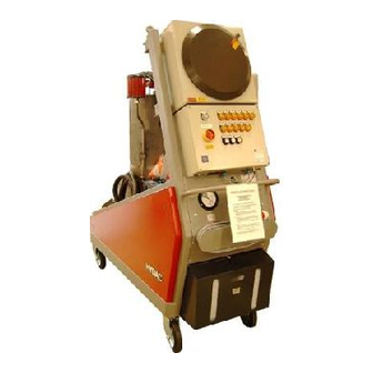
FAM Description FAM Description The FluidAqua Mobil FAM ATEX was developed for the dewatering, filtration and degassing of hydraulic and lubricating oils. It removes free water, emulsified water and a large percentage of the water to be found in solution. The integrated fluid filter ensures an efficient separation of solid particles. -
Page 27: Fam Overview
FAM overview FAM overview FAM 15/30/50/70 ATEX en(us) Page 27 / 96 BeWa FAM15-70 Atex 3193049h en(us) 2013-06-19 2013-06-19... - Page 28 FAM overview Item Name Suction strainer Inspections glass Inlet valve (2/2 directional control valve) Vacuum column Fluid level indication Level switch Vacuum pressure gauge Ball valve for the manual drainage of the vacuum column Evacuation pump with electrical motor Pressure relief valve Fluid filter for the separation of solid particles Fluid filter differential pressure indicator Ball valve for the manual drainage of the fluid filter...
-
Page 29: Fam Components
FAM overview FAM components Item Name Suction strainer Inspections glass Inlet valve (2/2 directional control valve) Vacuum column Level switch Vacuum pressure gauge Evacuation pump with electrical motor Pressure relief valve Fluid filter for the separation of solid particles Float switch in the oil pan Vacuum pump Fill level switch (dry-running protection of the evacuation pump) Air filter and air dryer... -
Page 30: Description Of Function
Description of function Description of function Switch on the FAM at the main switch. After the "Start delay" switch is activated, the inlet valve opens and the vacuum pump builds up the necessary vacuum. This vacuum causes the fluid which is to be purified to be sucked into the vacuum column. -
Page 31: Hydraulic Diagram
Hydraulic diagram Hydraulic diagram FAM 15/30/50/70 ATEX en(us) Page 31 / 96 BeWa FAM15-70 Atex 3193049h en(us) 2013-06-19 2013-06-19... - Page 32 Hydraulic diagram Item Name Suction strainer Inspections glass Inlet valve (2/2 directional control valve) Vacuum column Fluid level indication Level switch Vacuum pressure gauge Ball valve for the manual drainage of the vacuum column Evacuation pump with electrical motor Pressure relief valve Fluid filter for the separation of solid particles Fluid filter differential pressure indicator Ball valve for the manual drainage of the fluid filter...
-
Page 33: Possible Applications Of The Fam
Possible Applications of the FAM Possible Applications of the FAM Cleaning in Bypass Flow The FAM is connected with suction and pressure lines to the tank and cleans the medium to be found in it in constant bypass flow. The FAM is connected with suction and pressure lines to the tank and cleans the medium to be found there in continuous operation. -
Page 34: Fam Set-Up And Connection
FAM Set-up and Connection FAM Set-up and Connection CAUTION Rotary vane vacuum pump Hazardous to health Always make sure there is sufficient ► ventilation in the surrounding area of the unit. Air coming out of the rotary vane vacuum pump can contain particles of vacuum pump oil and/or the fluid. -
Page 35: Connecting The Fam
FAM Set-up and Connection Connecting the FAM All hoses on the FAM must be sufficiently conductive to properly discharge electrostatic charge buildup. If hoses are used, the ohmic resistance between the fittings—in this case between the FAM and the tank—may not exceed a limit value depending on the respective hose type. -
Page 36: Notes On Pipes And Hoses
FAM Set-up and Connection Notes on pipes and hoses NOTICE Non-permitted pressure at the inlet IN / outlet OUT Risk of malfunctions Determine the pressure to be anticipated at the inlet / outlet with the ► prescribed values. Make sure that the cross-section of the connected hoses/piping is at least as large as the cross-section of the inlet/outlet port sizes. - Page 37 FAM Set-up and Connection The pressure differential in a hydraulic line ( P ) depends on the (line) following: Flow rate Kinematic viscosity Pipe dimensions fluid density The pressure loss in straight pipes ( P ) can be calculated as follows: (line) ∆p ~ 6.8 * L / d...
-
Page 38: Connecting Suction Port (In)
FAM Set-up and Connection Connecting suction port (IN) NOTICE Overpressure at the suction port connection The unit will be damaged The pressure at suction port IN must be in the range from -0.25 to +2 ► bar. NOTICE Severe contamination The unit will be damaged Do not prime directly at the bottom of the tank. -
Page 39: Connecting The Pressure Port / Return-Flow Line
FAM Set-up and Connection Connecting the pressure port / return-flow line NOTICE Return port connection OUT closed off The unit will be damaged Check to be sure that all of the locking fixtures at the outlet are in ► "open" position each time before start-up To prevent air from entering the medium, make sure that the pressure hose with lance is always below the oil level in operation. -
Page 40: Electrical Connection Of The Fam
FAM Set-up and Connection Electrical Connection of the FAM DANGER Exposed electrical components in the switch cabinet Danger of fatal injury due to electric shock Any work involving the electrical system may ► only be done by a properly trained, certified electrician. -
Page 41: Check Direction Of Rotation
FAM Set-up and Connection Check direction of rotation Check the direction of rotation of the motor by switching it on briefly (jog mode). The FAM requires a clockwise rotating field at the connecting socket. NOTICE Incorrect phase sequence / rotation direction of the motor The pumps will be destroyed. -
Page 42: Preparing The Rotary Vane Vacuum Pump
The oil quantity between the MIN / MAX markings is ~ 0.3 liters You may only use synthetic vacuum pump oil to fill the vacuum pump in accordance with DIN 51506, Group VDL, ISO VG100. Available from HYDAC under the following part no.: Description Part no.:... -
Page 43: Filling The Seal Chamber Of The Evacuation Pump
Filling the seal chamber of the evacuation pump Filling the seal chamber of the evacuation pump Before initial commissioning, the seal chamber of the evacuation pump must be filled with the sealing medium ISO VG 10 ... ISO VG 100. For topping off, use the medium to be purified having a viscosity of ISO VG 10 …... -
Page 44: Operating Elements On The Unit
Operating Elements on the unit Operating Elements on the unit To operate the FAM, the following control and indicator elements are located on the control panel: Function Quantity Numbering Function keys S1 - S3 Operating status lamps H1 - H4 Malfunction message lamps H5 - H14 H10 H11... -
Page 45: Starting Up The Unit
Starting up the unit Starting up the unit NOTICE Connection IN / OUT closed The FAM will be destroyed Check to be sure that all of the locking fixtures at the inlet / outlet are ► in "open" position each time before start-up. After you have made all connections and completed the preparations for commissioning, switch on the FAM at the main switch. -
Page 46: Venting The Filter Housing
Starting up the unit Venting the filter housing WARNING Hot fluid Risk of burns Note that hot fluid may exit during bleeding. ► NOTICE Air in the fluid filter The filter element is not utilized completely Bleed the fluid filter after each shut-down / filter element replacement. ►... -
Page 47: Shut Off Fam
Starting up the unit Shut off FAM Press key "Run-down [S2]". Now the unit starts with the after-running phase. The inlet valve closes, the vacuum pump is switched off, and the vacuum column is emptied. Wait until the lamp H2 goes out, then move the main switch to the "Off" position. -
Page 48: Error Messages / Troubleshooting
Error messages / troubleshooting Error messages / troubleshooting Signal Inscription Cause Remedy Vacuum Maximum filling level Reduce the vacuum in chamber [03] in the vacuum the vacuum column, overfilled column exceeded. e.g. from 300 mbar (absolute) to 400 mbar Possible foam (absolute), increase the formation in the heating temperature to... - Page 49 Error messages / troubleshooting Signal Inscription Cause Remedy filled. the FAM for leaks. Motor protection Electric motor of Switch on motor switch Q2/Q3 evacuation or vacuum protection in the pump overloaded. electronic control unit, check operating viscosity, drain fluid from vacuum pump, rinse and fill up with fresh water.
-
Page 50: [H5] If The Vacuum Column Is Overfilled
Error messages / troubleshooting [H5] If the vacuum column is overfilled, Description Malfunction: "Vacuum column overfilled" Press the RESET button. Select manual menu 1, and start the evacuation pump Can the vacuum column be emptied within 3.5°minutes from level 03 to level 01? ->... -
Page 51: [H6] Inlet (In) Clogged
Error messages / troubleshooting [H6] Inlet (IN) clogged Description Malfunction: "Inlet clogged" Cause: No medium is making it into the vacuum column Check the setting of the shut off fittings in the suction line. If they are closed, then open them. Check/clean the suction screen. -
Page 52: [H7] Outlet (Out) Clogged
Error messages / troubleshooting [H7] Outlet (OUT) clogged Description Fault: "Outlet clogged" Cause: Medium cannot flow out of the vacuum column (emptying pump pressure limit = 5 bar) Check the position of the shut-off devices in the return line. If they are closed, then open them. -
Page 53: [H8] V-Pump Temperature
Error messages / troubleshooting [H8] V-pump temperature Description Malfunction: "V-pump temperature" Cause: The vacuum pump temperature is too high Check the fill level in the vacuum pump. If necessary, fill up with the correct vacuum pump oil Press the RESET button to acknowledge/reset the fault. Does the malfunction recur after the vacuum pump has started? ->... -
Page 54: [H9] Wrong Phase Sequence
Error messages / troubleshooting [H9] Wrong phase sequence Description Malfunction: "Wrong motor rotation" Switch off and disconnect the power unit. Replace the phases on the mains plug and check the mains voltage. Switch on the power for the unit, and start it by pressing the main switch. -
Page 55: [H10] Change Fluid Filter
Error messages / troubleshooting [H10] Change fluid filter Description Malfunction: "Replace fluid filter" Press the RESET button to acknowledge/reset the fault. Switch off the unit at the main switch. Close the ball cocks on the IN and OUT connections. Empty the filter housing via the drain ball valve. Replace the filter element according to the description on page Open the ball cocks on the IN and OUT connections. -
Page 56: [H11] Float Switch
Error messages / troubleshooting [H11] Float switch Description Malfunction: "Float switch" Empty the oil collecting pan. Press the RESET button to acknowledge/reset the fault. Start up the unit. Check the unit for leaks, and fix them. Does the malfunction reappear after ~ 2 seconds? ->... -
Page 57: [H12] E/V/R Pump Motor Protection
Error messages / troubleshooting [H12] E/V/R pump motor protection Description Malfunction: "E/V/R pump motor protection" Switch off and disconnect the power unit. Open the control cabinet door. Switch the motor protection switch and/or fuse that was tripped back on and check the setting of the motor protection switch and/or the voltage capacity of the fuse in accordance with the motor type plate and/or the heater type plate. -
Page 58: [H13] Dry-Running, E-Pump
Error messages / troubleshooting [H13] Dry-running, E-pump Description Fault "Dry running, E-pump" Cause: Insufficient inflow into the vacuum column. The suction-side pressure loss is too great. Possible remedies: Clean the suction screen Lower the suction height. Reduce the absolute pressure in the vacuum column e.g. -
Page 59: [H14] Level Switch 01/02(02/03)
Error messages / troubleshooting [H14] Level switch 01/02(02/03) Description Malfunction: Level switch 01/02(02/03) Switch off the unit at the main switch. Disconnect plug at the level sensor, and remove the level sensor. Manually check the switching points on the level switch ->... -
Page 60: [H15] V-Pump Pressure
Error messages / troubleshooting [H15] V-pump pressure Description Malfunction: "V-pump pressure" Cause: the pressure in the oil separator for the vacuum pump is too high. The air de-oiling element is used up / clogged. Replace the air de-oiling element. Press the RESET button to acknowledge/reset the fault. Does the malfunction recur after the vacuum pump has started? ->... -
Page 61: Performing Maintenance / Inspection
Performing maintenance / inspection Performing maintenance / inspection DANGER Risk of explosion Danger of fatal injury Perform all maintenance work outside of the ► ATEX danger zone. WARNING Hydraulic systems are under pressure Danger of bodily injury The hydraulic system must be depressurized ►... -
Page 62: Visual Checks
Performing maintenance / inspection Clean plastic parts only with a damp cloth. If defects which affect explosion protection are discovered during inspections, then the FAM is to be taken out of service until the defect is remedied. Repair and servicing work is not permitted on damaged flameproof enclosures (evacuation pump motor). -
Page 63: Overview Of Maintenance Intervals
Performing maintenance / inspection Overview of maintenance intervals Visual check for leaks Check to ensure the screwed fittings are securely tightened and retighten if necessary Check the measurement technology equipment / Underpressure manometer / Dynamic pressure manometer at the fluid filter Check fault indicator lamps Change the air filter (if this has not been required... - Page 64 Performing maintenance / inspection Replace oil, oil filter Clean the vacuum pump of dirt and dust. Fan cover, fan wheels, air grille, cooling fins, etc. Check flame arrester. (See operating instructions of vacuum pump) Check the measuring and security technology for proper functioning. (See operating instructions of vacuum pump) Change intake air filter, clean intake...
- Page 65 Performing maintenance / inspection Perform an electrical inspection Measure the engine power consumption of all engines and compare the values with the type label Perform electrical safety inspection in accordance with DIN VDE 0702 and/or corresponding national regulation. Measure power consumption of the heater and compare values with type label (applies only to versions with integrated heater)
-
Page 66: Electrical Inspection
Performing maintenance / inspection Electrical inspection In order to open the switch cabinet loosen the cover stop bolt and unscrew the cover by using the supplied handles (see picture, 2 pieces). To close the cover carefully screw it in up to the cover stop bolt, then tighten the bolt. -
Page 67: Filling The Seal Chamber Of The Evacuation Pump
Performing maintenance / inspection Is the terminal chamber clean? Is the connection performed correctly? Are the cables and leads inserted properly? Are all bolts and nuts tightened firmly? Are cable entries and stopping plugs seated correctly? Are all unused openings sealed with certified sealing elements? Are all covers and partition plates associated with energized components in place and firmly attached? Is the ground wire connected? -
Page 68: Lubricating Lock On The Electrical Cabinet
DIN 51502 K1-2 G-45. We recommend: Blasolube 300. You can obtain this lubricant from HYDAC as a spare part; the part no. is in the spare parts list. Proceed as follows to lubricate the threads: Switch the unit off, pull the mains plug and bring the unit out of the area at risk for explosion. -
Page 69: Replacing The Filter Element On The Fluid Filter
Performing maintenance / inspection Replacing the filter element on the fluid filter If the fault indicator lamp "Replace filter element" [H10]" lights up, replace the filter element on the fluid filter. For details see page 69. Filter element N15DMxxx (quantity and type dependent on version) ... - Page 70 Performing maintenance / inspection (1) Have a suitable drip tray on hand to catch the fluid. (2) Open the drain fitting, and collect the escaping fluid in the tray. Once the housing has been completely drained, close the drain fitting. Screw in the air bleed screw (x) by hand in a clockwise direction and tighten it firmly using a 10 mm Allen wrench.
- Page 71 Performing maintenance / inspection Turn the locking cap on the top filter element by 90° in counterclockwise direction (1) and lift the locking cap off (2). Turn all filter elements 90° in a counterclockwise direction, and remove them. FAM 15/30/50/70 ATEX en(us) Page 71 / 96 BeWa FAM15-70 Atex 3193049h en(us) 2013-06-19...
- Page 72 Performing maintenance / inspection Dispose of the old filter elements in an environmentally-friendly manner. Clean the inside of the filter housing of coarse dirt. Check the O-rings on the filter housing for damage. If necessary, replace them. Insert the filter element into the bayonet fitting (1), and lock it in place by turning each individual filter element 90°...
- Page 73 Lubricant containing a slip additive – HYDAC part no.: 3066287 12. Open all shut-off valves on the FAM (inlet and outlet).
-
Page 74: Checking The Fault Indicator Lamp
Performing maintenance / inspection 13. Fill the filter housing slowly. Slightly undo the air bleed screw (x). The air in the filter housing can escape via the slot on the air bleed screw. Bleed the filter housing through the air bleed screw (x) until operating fluid comes out. -
Page 75: Clean The Suction Strainer
Performing maintenance / inspection Clean the suction strainer. NOTICE Missing suction strainer Pump is disrupted Replace suction strainer ► Clean the suction strainer regularly. ► To protect the pump from coarse contamination particles and other foreign bodies, a dirt trap with a strainer insert is fitted at the pump inlet. This strainer insert must be cleaned at regular intervals, e.g. -
Page 76: Changing The Air Filter Element
Performing maintenance / inspection Changing the air filter element You will require: Air filter (for part-no., see replacement parts list) Unscrew the air filter by hand Screw on the new air filter by hand Vacuum pump maintenance The vacuum pump must be serviced by BUSCH Service every 16000 operating hours, but at the latest after 4 years. -
Page 77: Vacuum Pump Components
Performing maintenance / inspection Vacuum pump components FAM 15/30/50/70 ATEX en(us) Page 77 / 96 BeWa FAM15-70 Atex 3193049h en(us) 2013-06-19 2013-06-19... - Page 78 Performing maintenance / inspection Item Name Pressure switche / display unit Terminal box Oil filling screw plug Type label Oil separator Temperature switch Grounding connection Ring bolt Suction port connection Flame arrester with cut-off valve Flame arrester Gas outlet Axial-flow fan Oil sight glass Drain plug Air de-oiling element...
-
Page 79: Changing The Oil And Oil Filter Of The Vacuum Pump
Performing maintenance / inspection Changing the oil and oil filter of the vacuum pump The first oil change must take place after 100 operating hours. Subsequently, every six months or every 3000 operating hours. The following accessories are required for accomplishing these tasks: ... -
Page 80: Replacing The Air De-Oiling Element Of The Vacuum Pump
Performing maintenance / inspection Replacing the air de-oiling element of the vacuum pump Oil mist or increased current consumption by the drive engine (possibly via response from the motor protection switch) indicates a soiled air de-oiling element. To replace the air de-oiling element, proceed as follows: Unscrew and remove the 4 fastening screws on the gas outlet (l) and the flame arrester (k). -
Page 81: Test Vacuum Column Level Sensor
Performing maintenance / inspection Test vacuum column level sensor Philips screwdriver PH#2 + PH#3 Fork wrench SW13 Remove the four nuts on the vacuum column cover. Release the safety screw on the level sensor plug. Pull out the plug. -
Page 82: Switching Status - Level Sensor Vacuum Column/Sps
Performing maintenance / inspection Switching Status - Level Sensor Vacuum Column/SPS " " " " " " " " I0.3 I0.4 I0.5 I0.3 I0.4 I0.5 FAM 15/30/50/70 ATEX en(us) Page 82 / 96 BeWa FAM15-70 Atex 3193049h en(us) 2013-06-19 2013-06-19... -
Page 83: Testing The Float Switch In The Oil Pan
The unit continues to operate -> You have tested the function of the float switch positively. If the unit does not switch off after the lifting of the float switch and no fault message appears, contact the HYDAC Service. FAM 15/30/50/70 ATEX en(us) Page 83 / 96... -
Page 84: Replacing Filter Element On The Oil Mist Separator
Performing maintenance / inspection Replacing filter element on the oil mist separator Item Name Separator head Separator pot Clogging indicator Filling level display The oil mist separator is located between the vacuum column and the vacuum pump. A filter element is used to retain the oil mist and the oil in the oil mist separator and the oil is collected in the separator pot, where it is continuously suctioned off and returned to the vacuum column. -
Page 85: Replacing The Filter Element On The Oil Mist Separator
Performing maintenance / inspection Replacing the filter element on the oil mist separator Quit Automatic mode on the FAM. Afterwards, wait approximately 1 minute, until normal pressure (ambient pressure) has been established in the vacuum column. Rotate the separator pot [2] 1/8th of a turn to the left (bayonet seal) and remove from the bottom. -
Page 86: Replacement Parts And Accessories List
Replacement Parts and Accessories List Replacement Parts and Accessories List To ensure safe and reliable operation of the unit, use only original spare parts and accessories. When ordering spare parts, always indicate the unit designation with: Type / material no. / serial no. / year of manufacture. Name Part no. -
Page 87: Customer Service
Regular inspection and maintenance work is indispensable for ensuring trouble-free operation and long service life for your FluidAqua Mobil. Our HYDAC Servicenter offers you these tasks within agreed-upon time frames and at fixed prices. HYDAC SERVICE GMBH Friedrichsthaler Strasse 15a, Werk 13... -
Page 88: Storing The Fam/Taking It Out Of Operation
Storing the FAM/Taking it out of Operation Storing the FAM/Taking it out of Operation Drain the FAM completely, including all of its components, before putting it into storage. Pull out the power plug, and securely fasten the hoses and power cord to the FAM. -
Page 89: Technical Data
Technical Data Technical Data FAM 15 FAM 30 FAM 50 FAM 70 ATEX ATEX ATEX ATEX Filter size OLF15 OLF 30 OLF 45 OLF 60 Filter element N15DMxxx N15DMxxx N15DMxxx N15DMxxx Contents of the pressure 20 l 40 l 60 l 78 l chamber Contamination retention... -
Page 90: Index
Index Index Accessories ............5, 88 Gear pump ............91 ATEX .......1, 3, 19, 27, 29, 63, 70, 91 Hazard symbol ..........3, 13 Cause ........50, 51, 53, 54, 55, 60, 62 Hydraulic diagram ..........4, 32 Changing the filter element........66 Hydraulic oil............ - Page 91 Index Pressure setting............ 47 Proper/Designated Use ........3, 17 Publisher ..............2 Temperature..........19, 50, 80 Pump ..........51, 65, 66, 77, 91 Throttle valve..........29, 30, 33 to shut down ............23 Transport .............. 21 transporting ............24 Type label............. 80 Relative humidity ..........90 Remedy ............
- Page 96 HYDAC Filter Systems GmbH Industriegebiet Postfach 1251 66280 Sulzbach/Saar 66273 Sulzbach/Saar Germany Germany Phone: +49 (0) 6897 509 01 Central Fax: +49 (0) 6897 509 846 (Technical Department) Fax: +49 (0) 6897 509 577 (Sales Department) Internet: www.hydac.com E-mail: filtersystems@hydac.com...
Need help?
Do you have a question about the FluidAqua Mobil FAM 15 ATEX and is the answer not in the manual?
Questions and answers