
Related Manuals for Hydac FluidAqua Mobil FAM 10-P


Summary of Contents for Hydac FluidAqua Mobil FAM 10-P
- Page 1 FAM 10-P FAM 10/15-P FluidAqua Mobil Operating and Maintenance Instructions English (translation of original operating instructions) Document No.: 4052078...
-
Page 2: Imprint
Court of Registration: Saarbrücken, HRB 17216 Executive director: Mathias Dieter, Dipl.Kfm. Wolfgang Haering Documentation Representative Mr. Günter Harge c/o HYDAC International GmbH, Industriegebiet, 66280 Sulzbach / Saar Telephone: +49 (0) 6897 509 1511 Fax: +49 (0) 6897 509 1394 E-Mail: guenter.harge@hydac.com ©... -
Page 3: Table Of Contents
Contents Contents Imprint......................2 Documentation Representative ..............2 Contents ......................3 Preface......................7 Technical Support..................7 Modifications to the Product ................7 Warranty ......................7 Using the documentation ................8 Safety Information ..................9 Hazard symbols...................9 Signal words and their meaning in the safety information and instructions ....................10 Structure of the safety information and instructions........11 Observe regulatory information ..............11 Proper/Designated Use ................12 Improper Use or Use Deviating from Intended Use ........13... - Page 4 Contents Mobile version ...................26 Hydraulic diagram..................27 Function description ..................29 Possible Applications of the FAM ..............31 Cleaning in Bypass Flow ................31 Purifying and transferring by pumping ............31 FAM Set-up and Connection ..............32 Setting up the FAM ..................32 Connection overview .................33 Notes on pipes / hosing ................34 Connecting the inlet (IN).................36 Connect outlet (OUT) ................36 Preparing the Vacuum Pump..............37...
- Page 5 Contents Operating mode - MANU - OPERATOR (MANU2).........63 Operating mode - MANU - OPERATOR (MANU3).........63 Operating mode - MANU - OPERATOR (MANU4).........64 Operating mode - SETTINGS (SET) ............65 Set units ....................65 Set temperature..................66 Set pressure ...................66 Menu2......................67 Set (repeat testing interval) times............68 Read operating-hours counter..............68 Reset safety thermostat on the heater............69 Performing Maintenance ................70...
- Page 6 Contents 17. No measured value from CS. Check for flow........96 18. / 19. / 20. / 21. / 22. Motor protection switch Qx has tripped....97 23. Oil filter contaminated -> replace oil filter..........99 24. Oil tank of rotary vane vacuum pump is empty -> refill oil ....100 25.
-
Page 7: Preface
When making modifications or performing repair work to components affecting the safety of the product, the product may not be put back into operation until it has been examined and released by a HYDAC representative. Please notify us immediately of any modifications made to the product whether by you or a third party. -
Page 8: Using The Documentation
Preface Using the documentation Note that the method described for locating specific information does not release you from your responsibility of carefully reading these instructions prior to starting the unit up for the first time and at regular intervals in the future. WHAT do you want to know? I determine which topic I am looking for. -
Page 9: Safety Information
Safety Information Safety Information The unit was built according to the statutory provisions valid at the time of delivery and satisfies current safety requirements. Any residual hazards are indicated by safety information and instructions and are described in the operating instructions. Observe all safety and warning instructions attached to the unit. -
Page 10: Signal Words And Their Meaning In The Safety Information And Instructions
Safety Information Risk of burns due to hot surfaces Substances that are health hazards or irritants Signal words and their meaning in the safety information and instructions DANGER DANGER indicates a danger with a high risk and which will lead to death or serious injury if not avoided. -
Page 11: Structure Of The Safety Information And Instructions
Safety Information Structure of the safety information and instructions All warning instructions in this manual are highlighted with pictograms and signal words. The pictogram and the signal word indicate the severity of the danger. Warning instructions listed before an activity are laid out as follows: SIGNAL WORD Type and source of danger HAZARD SYMBOL... -
Page 12: Proper/Designated Use
Safety Information Proper/Designated Use Use the unit only for the application described in the following. The FAM is for dewatering, filtering and degassing hydraulic and lubricating oils. In addition, it removes free water, emulsified water and a large percentage of the water found in solution. Proper or designated use of the product extends to the following: ... -
Page 13: Improper Use Or Use Deviating From Intended Use
► below. Any use extending beyond or deviating therefrom shall not be considered intended use. HYDAC Filter Systems GmbH will assume no liability for any damage resulting from such use. The risk is borne exclusively by the machine owner. Improper use may result in hazards and/or will damage the unit. Examples of improper use: ... -
Page 14: Qualifications Of Personnel / Target Group
Safety Information Qualifications of personnel / target group Persons who work on the power unit must be aware of the associated hazards when using the power unit. Operating and specialist personnel must have read and understood the operating instructions, in particular the safety information and instructions, and applicable regulations before beginning work. -
Page 15: Wear Suitable Clothing
Unpacking the FAM Wear suitable clothing Loosely worn clothing increases the danger of getting caught or wound up in rotating parts and the danger of getting snagged on projecting parts. You can be severely injured or killed. Wear close-fitting clothing. ... -
Page 16: Transporting The Fam
Transporting the FAM Transporting the FAM CAUTION High empty weight 300 kg, depending on the version) ≈ Danger of bodily injury Use at least 2 persons to shift the FAM. ► NOTICE Using components for pushing/pulling The unit will be damaged. Never use the components to push or pull the unit. -
Page 17: Crane
Transporting the FAM Crane The unit has four eyelets on the frame for fastening lifting accessories. NOTICE Unsuitable lifting accessories The unit will be damaged / Components will be damaged / destroyed Use only suitable lifting accessories to raise or lash the unit. ►... -
Page 18: Decoding The Model Code Label
Decoding the model code label Decoding the model code label Details for identifying the filtration unit can be found on the name plates on the unit and the components. FluidAqua Mobil - FAM10/15-P en(us) Page 18 / 124 BEWA FAM10-15-P 4052078 en-us 2015-11-05.doc 2015-11-05... - Page 19 Decoding the model code label Item -> Description -> Power unit type label -> The name plate for the electro-cabinet is located on the inside -> Type label for the evacuation pump's electric motor -> Filtration unit electric motor name plate ->...
-
Page 20: Checking The Scope Of Delivery
Checking the scope of delivery Checking the scope of delivery Upon receiving the FAM check it for any damage in transit. The FAM may not be set up and installed unless it is in perfect order. Any damage in transit is to be reported to the forwarding agent or the department in charge immediately;... -
Page 21: Fam Description
FAM Description FAM Description The FluidAqua Mobil was developed for the dewatering, filtration and degassing of hydraulic and lubricating oils. It removes free water, emulsified water and a large percentage of the water to be found in solution. The integrated fluid filter ensures an efficient separation of solid particles. The drying and degassing of the medium is achieved by the neg. -
Page 22: Technical Specifications
FAM Description Technical specifications The FAM is able to dewater authorized fluids down to a water content of less than 1000 ppm. As an approximate guideline, the dimensioning of the FluidAqua Mobil can be defined in accordance with the tank volume. Tank volume in liters Installation size <... -
Page 23: Fam System Components
FAM Description FAM system components FluidAqua Mobil - FAM10/15-P en(us) Page 23 / 124 BEWA FAM10-15-P 4052078 en-us 2015-11-05.doc 2015-11-05... - Page 24 FAM Description Item Designation Suction strainer AquaSensor AS1000 Filling pump Non-return valve Vacuum column Heater (Option) Evacuation pump Check valve at the outlet Fluid filter for the separation of solid particles Filtration unit clogging indicator Fluid filter drainage Air filter and dryer Needle valve for vacuum setting Pressure sensor for vacuum measurement Vacuum pump...
-
Page 25: Dimensions
Dimensions Dimensions The different versions of the FAM series have the following illustrated dimensions. Stationary version FluidAqua Mobil - FAM10/15-P en(us) Page 25 / 124 BEWA FAM10-15-P 4052078 en-us 2015-11-05.doc 2015-11-05... -
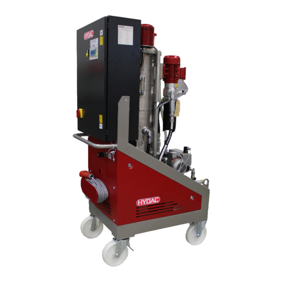
Page 26: Mobile Version
Dimensions Mobile version FluidAqua Mobil - FAM10/15-P en(us) Page 26 / 124 BEWA FAM10-15-P 4052078 en-us 2015-11-05.doc 2015-11-05... -
Page 27: Hydraulic Diagram
Hydraulic diagram Hydraulic diagram FluidAqua Mobil - FAM10/15-P en(us) Page 27 / 124 BEWA FAM10-15-P 4052078 en-us 2015-11-05.doc 2015-11-05... - Page 28 Hydraulic diagram Item Designation Suction strainer AquaSensor AS1000 Filling pump Non-return valve Vacuum column Heater (Option) Evacuation pump Check valve at the outlet Fluid filter for the separation of solid particles Differential pressure switch for filter monitoring Fluid filter drainage Air filter and dryer Needle valve for vacuum setting Pressure sensor for vacuum measurement...
-
Page 29: Function Description
Hydraulic diagram Function description = 4,5 bar ö Pö=0,1 bar G ½“ DN 25 20 bar = 1,0 bar ö 2,9 kW 1000 Not-Aus Max. 30 bar Min. G ½“ 1000 = 4,5 bar ö G 1" =0,2 bar ö Connect up the power unit in bypass flow with the tank that is to be cleaned. - Page 30 Hydraulic diagram the fluid and is then drawn off by the vacuum pump (16) through an oil mist separator (17). The saturation level of the sucked in fluid is measured continuously by the built-in AquaSensor (2) and displayed on the SIMATIC panel. The saturation level indicates what percent of maximum possible water is dissolved in the oil.
-
Page 31: Possible Applications Of The Fam
Hydraulic diagram Possible Applications of the FAM Cleaning in Bypass Flow The FAM is connected with suction and pressure lines to the tank and cleans the medium to be found there in continuous operation. Purifying and transferring by pumping The FAM is connected to the contaminated oil tank with the suction hose and pumps the fluid into the tank for the purified oil while cleaning it at the same time. -
Page 32: Fam Set-Up And Connection
FAM Set-up and Connection FAM Set-up and Connection CAUTION Rotary vane vacuum pump Hazardous to health Always make sure there is sufficient ► ventilation in the surrounding area of the unit. Air coming out of the rotary vane vacuum pump can contain particles of vacuum pump oil and/or the fluid. -
Page 33: Connection Overview
FAM Set-up and Connection Connection overview The stationary and mobile FAM versions have different scopes of delivery. The stationary FAM has positions 1-4, while the mobile FAM has positions 5- Item 28L / M36x2 FAM inlet connector (external thread)* Adapter G1 A Adapter (external thread)** FAM outlet... -
Page 34: Notes On Pipes / Hosing
FAM Set-up and Connection Notes on pipes / hosing NOTICE Non-permitted pressure at the inlet IN / outlet OUT Failure malfunction Determine the pressure to be anticipated at the inlet / outlet with the ► prescribed values. Note that the cross-section of the connected hoses/piping must be at least as large as the cross-section of the inlet/outlet port sizes. - Page 35 FAM Set-up and Connection The pressure loss in straight pipes ( P ) can be calculated as follows: (line) ∆p ≈ 6.8 * L / d * Q * V * D ∆ = Pressure differential in [bar] = Pipe length [m] = Internal pipe diameter [mm] = Flow rate [l/min] = Kinematic viscosity [mm²/s]...
-
Page 36: Connecting The Inlet (In)
FAM Set-up and Connection Connecting the inlet (IN) The suction pressure at the FAM inlet must be -0.4 bar. Use a negative pressure-resistant, flexible hose or a pipe for the suction-side connection. Note that the cross-section of the connected hoses/piping must be at least as large as the cross-section of the inlet/outlet port sizes. -
Page 37: Preparing The Vacuum Pump
MIN MAX filling level has been reached. Synthetic vacuum pump oil in accordance with DIN 51506, Group VDL, ISO VG100 must be used for topping up. HYDAC vacuum pump oil with following part no.: Description Part no.: Vacuum pump oil VE101... -
Page 38: Filling Rotary Vane Vacuum Pump
FAM Set-up and Connection Filling rotary vane vacuum pump Remove the safety screw for the plug at the level switch (1). Remove the plug (2) for the level switch. Unscrew the level switch (3) from the vacuum pump. Fill up with vacuum pump oil VE101 through the filling nozzle (4). -
Page 39: Electrical Connection Of The Fam
FAM Set-up and Connection Electrical connection of the FAM DANGER Exposed electrical components in the switch cabinet Danger of fatal injury due to electric shock Any work involving the electrical system may ► only be done by a properly trained, certified electrician. -
Page 40: Check Direction Of Rotation
FAM Set-up and Connection Check direction of rotation Check the direction of rotation of the motor by switching it on briefly (jog mode). The FAM requires a clockwise rotating field at the connecting socket. NOTICE Incorrect phase sequence / rotation direction of the motor The pumps will be destroyed. -
Page 41: Operating Elements On The Fam
Operating Elements on the FAM Operating Elements on the FAM The following operating elements are to be found on the FAM: Item Description Main switch with E-STOP function Alarm signal lamp (yellow) Control panel (for details see page 47) Vacuum gauge to set the pressure in the vacuum column SensorMonitoring Unit SMU1200 (for details see the corresponding operating instructions) FluidAqua Mobil - FAM10/15-P... -
Page 42: Starting Up The Fam
Starting up the FAM Starting up the FAM NOTICE Connection IN / OUT closed The FAM will be damaged. Check to be sure that all of the locking fixtures at the inlet / outlet are ► in "open" position each time before start-up. FluidAqua Mobil - FAM10/15-P en(us) Page 42 / 124... -
Page 43: Switching On The Fam
Starting up the FAM Switching on the FAM Move main switch to the "ON" position and wait until the "Fault" lamp lights up briefly (lamp test) and the following start screen will appear after 30 seconds. The most recently selected operating mode will be shown in the display. Select an operating mode with heater in the presence of viscosities ≥350 mm²/s. -
Page 44: Setting The Pressure In The Vacuum Column
Starting up the FAM Setting the pressure in the vacuum column For the current pressure in the vacuum column, consult the control panel. Rel. moisture: Nominal:30% Actual:33% 22°C P Ready for operation. Please press Start MENU1 START STOP RESET Pressure in the vacuum column Use the needle valve (D) to set the pressure in the vacuum column. - Page 45 Starting up the FAM With a lower pressure (such as 250 mbar), you achieve an lower residual water content. With a higher pressure (such as 500 mbar), you achieve a faster dewatering, especially with free water. By closing the needle valve (D) you reduce the absolute pressure and the required air-flow rate for dewatering the fluid.
-
Page 46: Shutting Off The Fam
Shutting off the FAM Shutting off the FAM Rel. moisture: Nominal:30% Actual:33% 22°C P Automatic mode MENU1 STOP F2 = STOP F4 = back to "MENU1" Press the "STOP" key. The power unit starts the after-run phase. All of the pumps will be switched off, except for the evacuation pump. Exception: If the heater is switched on, then a cooling phase of 60 seconds will intervene during which the heater is first shut off. -
Page 47: Control Panel Basic (Simatic Panel)
Control panel basic (SIMATIC PANEL) Control panel basic (SIMATIC PANEL) HELP SHIFT ENTER All functions are input and controlled using this control panel. Due to the size of the display it is necessary to radically shorten the texts relating to the operating modes and the functions. -
Page 48: Overview Of Operating Modes And Abbreviations
Control panel basic (SIMATIC PANEL) Overview of operating modes and abbreviations Abbreviation Description Menu 1: Operating mode Hand Manual menu Menu 2: an operating-hours counter, and Config Configuration menu Buttons: RH + T Relative humidity + temperature Temperature (only with heater option) Cont. -
Page 49: Overview Of Menu Structure
Control panel basic (SIMATIC PANEL) Overview of menu structure Menu1 Cont. ISO, SAE, NAS OM – Operating Mode DW+FT DWT+ DWT + FTB EW+H+FT DWT+H+FT DWT + H + FTB FT+H EW+FTB EW+H+FTB FTT+H DW+FT MAN. OPERATOR MANU 1 Manual Operation MANU 2 MANU 3... - Page 50 Control panel basic (SIMATIC PANEL) Menu2 Intervals an operating-hours counter, and Configuration FluidAqua Mobil - FAM10/15-P en(us) Page 50 / 124 BEWA FAM10-15-P 4052078 en-us 2015-11-05.doc 2015-11-05...
-
Page 51: Changing / Entering Values
Control panel basic (SIMATIC PANEL) Changing / entering values Meas. values: MENU1 Cont. -> Menu keys MAN. MENU2 -> Function key assignment -> Function keys The menu keys illustrated can be selected with the keys or by SHIFT means of the key combination , which is marked by framing made up of a line of dashes. -
Page 52: Menu1
Control panel basic (SIMATIC PANEL) Menu1 MENU1 Meas. values: MENU1 Cont. -> Menu keys MAN. MENU2 -> Function key assignment -> Function keys The menu keys shown can be selected with the keys . The selected menu key is marked by a dashed line around its circumference. The changeover to the selected menu is achieved with the key Menu keys Description... -
Page 53: Start Screen
Control panel basic (SIMATIC PANEL) Start screen The selected operating mode is shown in the upper line, the middle line shows the current operating status, and the key assignment is displayed in the lower line. You see this start screen only after switching on the power unit using the main switch. -
Page 54: Rh+P (Relative Humidity + Pressure)
Control panel basic (SIMATIC PANEL) RH+P (relative humidity + pressure) Start screen -> MENU1 -> RF-D Rel. moisture: Nominal:30% Actual:33% 22°C P Ready for operation. Please press Start MENU1 START STOP RESET START Start FAM Display in operating status "Ready for operation" and with the error message "Water content ≥... -
Page 55: T (Temperature)
Control panel basic (SIMATIC PANEL) T (Temperature) MENU1 -> T Heater: Hysteresis: 5°C l 55°C Ready for operation. Please press Start MENU1 START STOP RESET START Start FAM Display in operating status "Ready for operation" and with the error message "Water content ≥ 90%, measurement with CS not possible". -
Page 56: Selection Contamination (Cont.)
Control panel basic (SIMATIC PANEL) Selection Contamination (CONT.) MENU1 -> Cont. -> ISO (example, can also be SAE or NAS depending on sensor) 4 µ 6 µ 14 µ tgt: 4 µ 6 µ 14 µ Ready for operation. Please press Start START STOP RESET... -
Page 57: Operating Mode - Om
Control panel basic (SIMATIC PANEL) Operating Mode - OM MENU1 -> OM Operating mode: Dewatering + Filtration DWT+ DW+FT NEXT DW+FT Dewatering and Filtration DWT+ Dewatering up to and Filtration Filtration NEXT Other operating modes Only operating modes that can be selected are displayed. A change of operating mode is possible at any time during automatic operation. -
Page 58: Operating Modes - Brief Overview / Brief Description
Control panel basic (SIMATIC PANEL) Operating modes - Brief overview / Brief description The following offers a brief description of the operating modes: Operating Description modes: DW+FT = Dewatering The fluid will be simultaneously dewatered and filtered. Filtration DWT+ = Dewatering The fluid will be simultaneously dewatered up to and and filtered. - Page 59 Control panel basic (SIMATIC PANEL) once again after this time, then the FAM will switch off once again and the recurrent inspection interval runs again. DWT + H + = Dewater to The fluid will be simultaneously dewatered + Heat + and filtered and heated up to the prescribed Filter to temperature (see page 55).
- Page 60 Control panel basic (SIMATIC PANEL) recurrent inspection interval runs again. = Filter to The fluid will only be filtered. The FAM operates until a specified cleanliness code has been reached (see page 56). Then the FAM switches off. Now the recurrent inspection interval starts (time until the unit switches on again, see page 68).
-
Page 61: Operating Mode - Dewater To / Filter To
Control panel basic (SIMATIC PANEL) Operating mode - Dewater to / Filter to The operating mode "Filter to" is possible only up to a relative humidity of 90%. The CS is switched off in situations involving >90% or unmanaged water. The following message is output when the contamination menu is selected: "Oil saturation >90%. -
Page 62: Operating Mode - Manu
MENU1 -> MANUAL Selection Manual oper OPERA- MENU1 SERVICE OPERATOR Manual operation for operator SERVICE Manual operation for HYDAC Service (password- protected) MENU1 Back to MENU1 Operating mode - MANU – OPERATOR (MANU1) MENU1 -> MANUAL -> Operator manual1 Manual- operation Back... -
Page 63: Operating Mode - Manu - Operator (Manu2)
Control panel basic (SIMATIC PANEL) Operating mode - MANU - OPERATOR (MANU2) MENU1 -> MANUAL -> Operator -> Continue manual2 Back NEXT = back to "Manual1" Menu Switching vacuum pump on/off Switching return valve on/off Switching off the water drainage valve (present only with water ring vacuum pump) Operating mode - MANU - OPERATOR (MANU3) MENU1 ->... -
Page 64: Operating Mode - Manu - Operator (Manu4)
Control panel basic (SIMATIC PANEL) Operating mode - MANU - OPERATOR (MANU4) MENU1 -> MANUAL -> Operator -> Continue -> Continue -> Continue manual4 Back = back to "Manual3" Menu Recirculating pump FluidAqua Mobil - FAM10/15-P en(us) Page 64 / 124 BEWA FAM10-15-P 4052078 en-us 2015-11-05.doc 2015-11-05... -
Page 65: Operating Mode - Settings (Set)
Control panel basic (SIMATIC PANEL) Operating mode - SETTINGS (SET) MENU1 -> Settings Language selected: ENGLISH SELECT UNITS LANGUA MENU1 SELECT = Press the F1 key repeatedly until the desired language LANGUAGE appears. UNITS = Switch over to Units menu MENU1 = Switch to MENU1 Set units... -
Page 66: Set Temperature
Control panel basic (SIMATIC PANEL) Set temperature MENU1 -> Settings -> Units -> Temperature Temperature °C °F back °C Temperature display in °C °F Temperature display in °F back Back to Units menu Set pressure MENU1 -> Settings -> Units -> Pressure Pressure mbar back... -
Page 67: Menu2
Times for the recurrent inspection interval for the "Cleaning VALS until" and/or "Dewatering to" operating mode Display operating hours meter CONFI FAM Configuration – Access password-protected (For HYDAC Service only) MENU1 = Switch to MENU1 FluidAqua Mobil - FAM10/15-P en(us) Page 67 / 124 BEWA FAM10-15-P 4052078 en-us 2015-11-05.doc... -
Page 68: Set (Repeat Testing Interval) Times
Control panel basic (SIMATIC PANEL) Set (repeat testing interval) times Repeat testing interval: Intervals nominal minutes 0 elapsed minutes MENU2 Display: TRG MIN: Inspection repeating interval: Is the time after which the FAM switches on again after an automatic switch-off in the operating mode "Dewater to"... -
Page 69: Reset Safety Thermostat On The Heater
Control panel basic (SIMATIC PANEL) Reset safety thermostat on the heater The safety thermometer is triggered when the flow of oil through the heater is too low or if the thermostat is damaged. After the fault has been remedied, the safety thermostat can be reset by pressing the green key (C) in the head. -
Page 70: Performing Maintenance
Performing Maintenance Performing Maintenance Before performing any maintenance work, pull out the plug on the FAM and wind up the power cord to prevent the unit from being switched on again. The Unit is to be disconnected from the power supply and protected against being inadvertently switched back on when performing any maintenance, servicing, inspection or repair work. - Page 71 Performing Maintenance Replacing the Air De-oiling Element 80 Check and clean the ventilator hood Emptying / filling pump Check and clean the ventilator hood Fluid filter Changing the filter element Emptying and cleaning the filter housing Active carbon filter Change the carbon filter Condensate separator Changing the filter element on the condensate separator...
- Page 72 Performing Maintenance and/or corresponding national regulation. Measure power consumption of the heater and compare values with type label (applies only to versions with integrated heater) Function Test Testing the oil pan float switch Clean and check the level sensor in the vacuum column Completely replace all of the hoses after 5 years.
-
Page 73: Function Testing Of The Fault Indicator Lamp
4. The air filter replacement has been completed. Checking the AquaSensor Check the AquaSensor annually with the calibration and adjustment set (HYDAC p/no. 3122629). Replace the AquaSensor if it exhibits great deviations. The part no. can be found in the spare parts list. -
Page 74: Change The Active Carbon Filter Cartridge
Performing Maintenance Change the active carbon filter cartridge The active carbon filter cartridge absorbs oil vapors, odors and flavoring agents from the exhaust air. The weight of the active carbon filter can be used to determine when the filter is saturated. Check the weight of the active carbon filter as soon as you notice a deterioration in the quality of the exhaust air. -
Page 75: Performing Maintenance On The Condensate Separator
Performing Maintenance Performing maintenance on the condensate separator A condensate separator is included to neutralize odors. The condensate separator comprises the following parts: Item Designation container Filter element Seal Demister Seal Inspections glass Drain ball valve Profile clamp FluidAqua Mobil - FAM10/15-P en(us) Page 75 / 124 BEWA FAM10-15-P 4052078 en-us 2015-11-05.doc... -
Page 76: Changing The Filter Element On The Condensate Separator
Performing Maintenance Changing the filter element on the condensate separator The filter element is replaced at the same intervals as the carbon filter canister. To replace the filter element on the condensate separator, proceed as follows: Open the profile clamp (12) and pull the base down and off. The base contains approx. -
Page 77: Cleaning The Suction Strainer
Performing Maintenance Cleaning the suction strainer NOTICE Operation without a suction strainer The pump will be destroyed The unit may not be operated without the suction strainer. ► Clean the suction screen regularly. ► To protect the pump from coarse contamination particles and other foreign bodies, a dirt trap with a strainer insert is fitted at the pump inlet. -
Page 78: Rotary Vane Vacuum Pump Components
Performing Maintenance Rotary vane vacuum pump components Item Designation Oil filler neck Oil drain Oil sight glass Oil separator Suction port connection Gas outlet Safety screw on the plug Plug for the level sensor Level switch in the vacuum pump The following descriptions are in reference to these positions. -
Page 79: Performing An Oil Change
Performing Maintenance Performing an oil change The first oil change must take place after 100 operating hours. This increases the interval to approx. 3,000 hours or every six months. The vacuum pump must be at operating state temperature when the oil is changed: Put the FAM into operation for 10 minutes. -
Page 80: Replacing The Air De-Oiling Element
Performing Maintenance Replacing the Air De-oiling Element Oil mist or increased electricity consumption by the drive engine (response of the engine protection switch) are signs of a soiled air de-oiling element. To replace the air de-oiling element, proceed as follows: Remove the ventilation cover (i) from the oil separator (g). -
Page 81: Replacing The Filter Element On The Fluid Filter
Performing Maintenance Replacing the filter element on the fluid filter As soon as the error message "change fluid filter" appears on the display the filter should be taken out of the housing and be replaced by a new one. To change the filter element, proceed as follows: Switch off the system and close the locking devices at the inlet and outlet ports. - Page 82 Performing Maintenance Pull the filter bowl including filter element downwards. Remove (2) the filter element from the filter bowl by turning slightly (1). Dispose of the used filter element in an environmentally correct manner. FluidAqua Mobil - FAM10/15-P en(us) Page 82 / 124 BEWA FAM10-15-P 4052078 en-us 2015-11-05.doc 2015-11-05...
- Page 83 Performing Maintenance Clean the inside of the filter bowl of dirt and deposits. Check the O-ring on the filter bowl for damage. Replace it if necessary. Moisten the O-ring on the filter bowl with the operating medium. Moisten the O-rings on the new filter element with the operating medium.
- Page 84 Performing Maintenance Turning it slightly, press the new filter element down into the mount on the filter bowl. 10. Push the filter bowl with the filter element up into the mount on the filter head. FluidAqua Mobil - FAM10/15-P en(us) Page 84 / 124 BEWA FAM10-15-P 4052078 en-us 2015-11-05.doc 2015-11-05...
- Page 85 Performing Maintenance 11. Push the housing clamp (1) up around the filter bowl over the bead on the filter bowl / filter head. Tighten the housing clamp with an Allen wrench SW 6mm in a clockwise direction. The tightening torque is 5 Nm. 12.
-
Page 86: Testing The Float Switch In The Oil Pan
If the unit does not switch off after the lifting of the float switch and no fault message appears, contact the HYDAC Service. Checking the settings on the heater (optional) Under normal operating conditions the heater element is maintenance-free. -
Page 87: Error Messages / Troubleshooting
Error messages / Troubleshooting Error messages / Troubleshooting NOTICE Switch off the FAM at the main switch before opening the control cabinet door The main switch will be destroyed. Do not open the control cabinet door if the main switch is not in OFF ►... -
Page 88: Cs+Pump Switched Off. Cs Fault. Start 10 New Attempts With Reset
Error messages / Troubleshooting If several errors occur, then the most recently occurring message will be displayed first. One can used the arrow keys to scroll through the individual fault messages. All of the error messages shown in the display are equipped with a number. It is very easy to find the error message again in this Chapter by using the number as a reference. -
Page 89: Flow At Fam Inlet Has Been Too Low For 5 Minutes. Check The Fam Inlet
Start the unit by pressing the F1 key. ->a. The fault is repeated. -> proceed to Step 10. ->b. The fault is not repeated. -> proceed to Step 11. Contact the HYDAC service department. The fault is repaired. FluidAqua Mobil - FAM10/15-P en(us) Page 89 / 124 BEWA FAM10-15-P 4052078 en-us 2015-11-05.doc... -
Page 90: Fam Outlet Is Blocked
Start the unit by pressing the F1 key. ->a. The fault is repeated. -> proceed to Step 10. ->b. The fault is not repeated. -> proceed to Step 11. Contact the HYDAC service department. The fault is repaired. FluidAqua Mobil - FAM10/15-P en(us) Page 90 / 124 BEWA FAM10-15-P 4052078 en-us 2015-11-05.doc... -
Page 91: Error, Float Switch Of Rotary Vane Vacuum Pump At Fill Level Min. / Fill Level Overflow
Replace the level switch. -> proceed to Step 10. Replace the damaged parts. -> proceed to Step 10. The PLC is defective -> contact the HYDAC Service Department. The fault is repaired. FluidAqua Mobil - FAM10/15-P en(us) Page 91 / 124 BEWA FAM10-15-P 4052078 en-us 2015-11-05.doc... -
Page 92: 6. Error, Float Switch Of Vacuum Column At Fill Level Max And/Or Fill Level Overflow
Replace the level switch. -> proceed to Step 10. Replace the damaged parts. -> proceed to Step 10. The PLC is defective -> contact the HYDAC Service Department. The failure is repaired. FluidAqua Mobil - FAM10/15-P en(us) Page 92 / 124 BEWA FAM10-15-P 4052078 en-us 2015-11-05.doc... -
Page 93: 12. / 14. / 15. Cable Break
Error messages / Troubleshooting 11. / 12. / 14. / 15. Cable break Cause: Error 11. / 12. / 14. / 15. The signal is immediately active after the lamp test (except with AS temperature: 5 s), error message flashes on the display, the FAM continues however to run. - Page 94 F1 key. ->a. The fault is repeated. -> proceed to Step 5. ->b. The fault is not repeated. -> proceed to Step 13. Contact the HYDAC service department. The fault is repaired. FluidAqua Mobil - FAM10/15-P en(us) Page 94 / 124 BEWA FAM10-15-P 4052078 en-us 2015-11-05.doc...
-
Page 95: No Defined Value From Cs
Error messages / Troubleshooting 16. No defined value from CS Cause: The charge pump for the CS runs for 2 minutes in Automatic mode. The CS has been reporting "no measured value from CS" for 4 minutes. The message is shown on the CS display. The FAM continues to run. -
Page 96: No Measured Value From Cs. Check For Flow
Error messages / Troubleshooting 17. No measured value from CS. Check for flow Cause: The charge pump for the CS runs for 2 minutes in Automatic mode. The CS has been reporting "no measured value from CS" for 4 minutes. The message is shown on the CS display. -
Page 97: 19. / 20. / 21. / 22. Motor Protection Switch Qx Has Tripped
Error messages / Troubleshooting 18. / 19. / 20. / 21. / 22. Motor protection switch Qx has tripped. Cause: The motor protection switch has tripped, due to an overload in the motor-pump group. The FAM switches off after 1.8 seconds. Remedy: Perform the following steps: Description... - Page 98 F1 key. ->a. The fault is repeated. -> proceed to Step 12. ->b. The fault is not repeated. -> proceed to Step 13. Contact the HYDAC service department. The fault is repaired. FluidAqua Mobil - FAM10/15-P en(us) Page 98 / 124 BEWA FAM10-15-P 4052078 en-us 2015-11-05.doc...
-
Page 99: Oil Filter Contaminated -> Replace Oil Filter
10. ->a. The test resulted in no errors. -> proceed to Step 12. ->b. The errors found were -> proceed to Step 6. eliminated. The PLC is defective -> contact the HYDAC Service Department. The fault is repaired. FluidAqua Mobil - FAM10/15-P en(us) Page 99 / 124 BEWA FAM10-15-P 4052078 en-us 2015-11-05.doc... -
Page 100: Oil Tank Of Rotary Vane Vacuum Pump Is Empty -> Refill Oil
Error messages / Troubleshooting 24. Oil tank of rotary vane vacuum pump is empty -> refill oil Cause: The MIN switch point in the oil tank of the rotary vane vacuum pump has been reached. The message appears at once on the display. The FAM goes into the after-running phase and switches off. -
Page 101: Oil Tank Of Rotary Vane Vacuum Pump Is Too Full -> Drain Oil
Error messages / Troubleshooting 25. Oil tank of rotary vane vacuum pump is too full -> drain oil Cause: The MAX switch point in the oil tank of the rotary vane vacuum pump has been reached for 10 minutes. The message appears on the display. -
Page 102: Heater Safety Thermostat Triggered
Error messages / Troubleshooting 26. Heater safety thermostat triggered Cause: Thermostat trips during operating mode with heater. The FAM goes into the after-running phase and switches off. If an operating mode is selected for which no heater is switched on, then it is possible to operate the FAM. The message will however be displayed and can be reduced with ESC. - Page 103 F1 key. ->a. The fault is repeated. -> proceed to Step 13. ->b. The fault is not repeated. -> proceed to Step 21. Contact the HYDAC service department. The fault is repaired. FluidAqua Mobil - FAM10/15-P en(us) Page 103 / 124 BEWA FAM10-15-P 4052078 en-us 2015-11-05.doc...
-
Page 104: Fuse F2 Has Tripped
Error messages / Troubleshooting 27. Fuse F2 has tripped Cause: The F2 fuse triggers. A message appears on the display. The FAM switches off at once. The fault indicator lamp is not flashing. Remedy: Perform the following steps: Description Message: 27. -
Page 105: Heater Fuse Has Tripped
Error messages / Troubleshooting 28. Heater fuse has tripped Cause: The heater fuse has tripped. The FAM goes into the after-running phase and switches off. Remedy: Select an operating mode without heater. The message will however be displayed and can be reduced with ESC. - Page 106 Error messages / Troubleshooting ->b. The fault is not repeated. -> proceed to Step 15. Contact the HYDAC service department. The fault is repaired. FluidAqua Mobil - FAM10/15-P en(us) Page 106 / 124 BEWA FAM10-15-P 4052078 en-us 2015-11-05.doc 2015-11-05...
-
Page 107: Check Phase Sequence
11. ->a. The fault is repeated. -> proceed to Step 12. ->b. The fault is not repeated. -> proceed to Step 13. Contact the HYDAC service department. The fault is repaired. FluidAqua Mobil - FAM10/15-P en(us) Page 107 / 124 BEWA FAM10-15-P 4052078 en-us 2015-11-05.doc... - Page 108 Error messages / Troubleshooting NOTICE Incorrect phase sequence The motors / pumps rotate in the wrong direction. Using manual operation always check the direction of rotation of the ► motors after they have been replaced. FluidAqua Mobil - FAM10/15-P en(us) Page 108 / 124 BEWA FAM10-15-P 4052078 en-us 2015-11-05.doc 2015-11-05...
-
Page 109: Malfunction Cs Flow Too Low
Error messages / Troubleshooting 30. Malfunction CS flow too low Cause: The charge pump for the CS runs for 2 minutes in automatic mode. The CS reports "Flow too low" or "Device error" for 4 minutes, message appears in the display of the CS. -
Page 110: Dry-Running Evacuation Pump
Error messages / Troubleshooting 32. Dry-running Evacuation Pump Cause: The evacuation pump is running and the MIN switch point in the vacuum column was reached/was not reached. The timer runs 2 minutes and the MIN switch point is not exceeded during this time. The FAM switches off at once, the message appears on the display. -
Page 111: Vacuum Column Overflow -> Drain Vacuum Column And Troubleshoot Cause
Error messages / Troubleshooting 33. Vacuum column overflow -> drain vacuum column and troubleshoot cause Cause: The E-STOP MAX switch point in the vacuum column was reached. All of the pumps except the evacuation pump are switched off. The timer runs 4 minutes and 10 seconds. The level did not fall below the MAX switch point during the time, the FAM switches off at once, message appears on the display. - Page 112 Error messages / Troubleshooting Emptying duration for the vacuum column in seconds: Voltage with 50 Hz Voltage with 60 Hz Filling level marking Filling level marking E-STOP E-STOP 31.8 50.8 29.4 36.8 47.0 39.7 19.6 24.5 31.3 18.7 23.3 29.8 23.4 29.2 37.3...
-
Page 113: Oil Pan Too Full -> Drain Oil Pan And Seal Leak
Error messages / Troubleshooting 34. Oil pan too full -> drain oil pan and seal leak Cause: The float switch in the tray was actuated. The message appears on the display after 1.8 seconds, and the FAM switches itself off. Remedy: Perform the following steps: Description... -
Page 114: Saturation Oil >= 90%. Measurement With Cs 1Xxx Not Possible
Error messages / Troubleshooting 37. Saturation oil >= 90%. Measurement with CS 1xxx not possible! Cause: Error-free measurement of contamination is not possible with a water content ≥90%. The charge pump of the CS is switched off. If you selected an operating mode for which the CS controls the FAM, then the FAM will automatically jump into a similar operating mode without control by the CS. -
Page 115: Spare Parts
Spare parts Spare parts Qty. Designation Part no. Breather filter 0160 MU 003 M 1265765 Suction strainer 1" assy., 635624 consisting of: 1x strainer insert, 250µm 6016797 1x sealing ring 3186928 3/2-directional control valve 3642696 Pressure hose, Length = 5 m 6031686 Suction hose, Length = 5 m 6031685... -
Page 116: Contact / Service
Regular inspection and maintenance work is indispensable for ensuring trouble-free operation and long service life for your FluidAqua Mobil. Our HYDAC Servicenter offers you these tasks within agreed-upon time frames and at fixed prices. HYDAC SERVICE GMBH Friedrichsthaler Str. 15A, Werk 13... -
Page 117: Taking The Unit Out Of Operation
Taking the unit out of operation Taking the unit out of operation Drain the unit completely, including all of its components, the same way as is done before putting it into storage. Pull out the power plug and securely fasten the hoses and power cord to the unit. -
Page 118: Technical Details
Technical details Technical details Refer to the type label for specific data of the unit. FAM10 FAM 10/15 Flow rate 10 l/min @ 50Hz 15 l/min @ 50Hz Electrical power consumption 1500 W without heater 2000 W without heater 4400 W with heater 4900 W with heater Empty weight ≈... -
Page 119: Model Code
Model Code Model Code A - 40 - R - H - B - A - 00 Product FAM = FluidAqua Mobil Installation size = 10 l/min @ 50 Hz 12 l/min @ 60 Hz 10/15 = 15 l/min @ 50 Hz 18 l/min @ 60 Hz Operating fluid ®... -
Page 120: Eu Declaration Of Conformity
Documentation Representative: Mathias Dieter, Dipl.Kfm. Wolfgang Haering Mr. Günter Harge Registered seat of company: 66280 Sulzbach / Saar - Germany c/o HYDAC International GmbH, Industriegebiet, 66280 Sulzbach / Saar Registry Court: Saarbrücken, HRB 17216 Telephone: +49 (0) 6897 509 1511... - Page 121 Factory setting...........56, 57, 70 Fault indicator lamp ..........25 ambient temperature ......20, 23, 34, 121 filling ... 30, 31, 39, 40, 45, 50, 64, 65, 73, 81, 82, 91, AquaSensor...5, 25, 29, 31, 56, 72, 73, 75, 122 Filter ... 4, 13, 50, 60, 61, 62, 63, 70, 77, 97, 98, 111, 116, 117, 121, 122 Filter element.........77, 117, 121 Filter element type ..........
- Page 122 Index Measures.............. 11 Rigid caster ............25 Mineral oil ............. 37 Rotary vane vacuum pump..5, 34, 72, 80, 121, 122 Model code ............20 Motor protection switch........6, 99 mounting............... 34 SAE ............51, 58, 122 Safety thermostat ..........105 select ...............8, 116 NAS ............
- Page 124 HYDAC FILTER SYSTEMS GMBH Industriegebiet Postfach 1251 66280 Sulzbach/Saar 66273 Sulzbach/Saar Germany Germany Phone: +49 (0) 6897 509 01 Central Fax: +49 (0) 6897 509 9046 Technical Department Fax: +49 (0) 6897 509 577 Sales Department Internet: www.hydac.com E-mail: filtersystems@hydac.com...
Need help?
Do you have a question about the FluidAqua Mobil FAM 10-P and is the answer not in the manual?
Questions and answers