Sign In
Upload
Download
Table of Contents
Contents
Add to my manuals
Delete from my manuals
Share
URL of this page:
HTML Link:
Bookmark this page
Add
Manual will be automatically added to "My Manuals"
Print this page
×
Bookmark added
×
Added to my manuals
Manuals
Brands
Hydac Manuals
Water Filtration Systems
OFU
Operating and maintenance instructions manual
Hydac OFU Operating And Maintenance Instructions Manual
Hide thumbs
1
2
3
4
5
6
7
8
9
10
11
12
13
14
15
16
17
18
19
20
21
22
23
24
25
26
27
28
29
30
31
32
33
34
35
36
37
38
39
40
41
42
43
44
45
46
47
48
49
50
51
52
53
54
55
56
57
58
59
60
61
62
63
64
65
66
67
68
69
70
71
72
73
74
75
76
77
78
79
80
81
82
83
84
page
of
84
Go
/
84
Contents
Table of Contents
Bookmarks
Table of Contents
Table of Contents
1 General
Target Group of the Manual
Tab. 1 Target Group
Illustrations in the Manual
Illustration on the Title Page
Fig. 1 Overview / Labeling of the Title Page
Representation of Procedural Instructions
Representation of Requirements
Representation of Intermediate Results/Results
Representation of Warning/General Safety Information
Signal Words and Their Meaning in the General Safety Information
Supplementary Symbols
Exclusion of Liability/Warranty
Notes on Copyright
2 Safety
Target Group/Required Personnel Qualification
Tab. 2 Target Group / Required Personnel Qualification
Hazard Symbols / Pictograms
Danger Notifications
Observing Regulatory Information
Observing Environmental Precautions
Wear Suitable Clothing
Stoppage in an Emergency (EMERGENCY STOP)
Fire-Fighting / Extinguishing a Fire
Fig. 2 Fire Protection Class B
Fig. 3 Minimum Distance for Fire Fighting
3 Technical Specifications
Proper/Designated Use
Improper Use or Use Deviating from Intended Use
Checking the Scope of Delivery
Tab. 3 Checking the Scope of Delivery
Fig. 4 Checking the Scope of Delivery
Dimensions
OFU - Dimensions
Fig. 5 Dimensions of the OFU
Hydraulic Diagram
Technical Data
Tab. 5 Technical Data
Decoding the Name Plate
Fig. 6 Decoding the Type Label
Tab. 6 Decoding the Type Label
Model Code
Fig. 7 Model Code OFU
4 Device Description
Fig. 8 Components/Operating Elements of the OFU
5 Transporting/Storing the Filter Unit
Tab. 4 Technical Data
6 Setting up / Assembly / Integration of the Filter Unit
Avoiding Siphoning
Fig. 9 Avoiding Siphoning
Measuring or Displaying the Back Pressure / Differential Pressure
Fig. 10 Measure or Display Dynamic Pressure / Differential Pressure
Avoiding the Mixing of Oils - Emptying the Filter Unit
Making the Electrical Connections
Connecting the Filter Unit with a Three-Phase Electric Motor
Connecting the Suction/Pressure Port
Fig. 11 Pressure Loss Formula
Attaching / Connecting the Suction / Pressure Hoses (Accessories)
Inserting the Filter Element
Commissioning
7 Operation
Activate the Main Switch
Fig. 12 Activate the Main Switch
Observing the Optical Clogging Indicator (Optional)
Fig. 13 Observe the Optical Clogging Indicator
8 Performing Maintenance
Maintenance Table
Changing the Filter Element
Checking/Cleaning the Strainer
9 Decommissioning / Disposal
Temporary Shutdown
Final Decommissioning
Disposal
10 Appendix
EC Declaration of Conformity
Locating Spare Parts
Filter Elements - Size 1300
Order Filter Elements
Tab. 7 Filter Elements - Size 1300
Filter Elements - Size 2600
Tab. 8 Filter Elements - Size 2600
Clogging Indicators - Technical Data
Differential Pressure Indicator, Visual - VM X B.X
Fig. 14: Differential Pressure Indicator - Visual VM X B.X
Tab. 9: Differential Pressure Indicator -Visual VM X B.X
Fig. 15: Differential Pressure Gauge, Visual VM X Bm.X
Tab. 10: Differential Pressure Indicator, Visual VM X Bm.X
Differential Pressure Gauge, Electric (VM X C.X)
Fig. 16 Differential Pressure Indicator, Electrical VM X C
Differential Pressure Gauge, Electric (VM X D.X /-L-XX)
Fig. 17 Differential Pressure Indicator, Electrical VM X D.X /-Lxx
Tab. 12 Differential Pressure Indicator, Electrical VM X D.X / -Lxx
Contacting Customer Service
Tab. 13 HYDAC Service Deutschland
Table of Illustrations
Glossary
Index
Advertisement
Quick Links
Download this manual
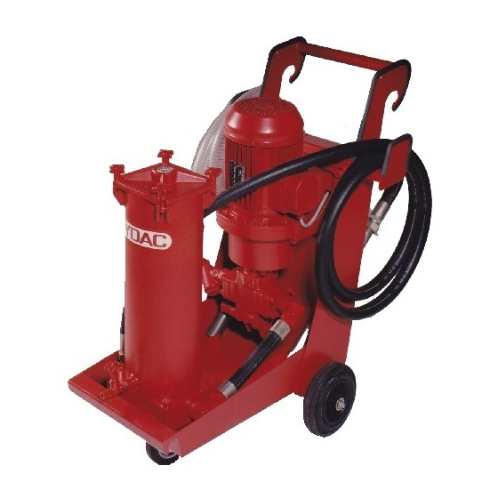
OFU
Filtromat
Operating and Maintenance Instructions
English (translation of original instructions)
Document No. : 3120755e
Follow these instructions for proper and safe use.
Keep for future reference.
Table of
Contents
Previous
Page
Next
Page
1
2
3
4
5
Advertisement
Chapters
Table of Contents
3
Table of Illustrations
75
Table of Contents
Need help?
Do you have a question about the OFU and is the answer not in the manual?
Ask a question
Questions and answers
Subscribe to Our Youtube Channel
Related Manuals for Hydac OFU
Water Filtration Systems Hydac Filtromat OF5F Operating And Maintenance Instructions Manual
(36 pages)
Water Filtration Systems Hydac OF5 CM Operating And Maintenance Instructions Manual
Filtromat (72 pages)
Water Filtration Systems Hydac OF5 CM Operating And Maintenance Instructions Manual
Filtromat (80 pages)
Water Filtration Systems Hydac Filtromat OF5 C with FCU Operating And Maintenance Instructions Manual
(44 pages)
Water Filtration Systems Hydac OffLine Filter BiDirectional OLFBD Series Installation And Maintenance Instructions Manual
(52 pages)
Water Filtration Systems Hydac OLF Series Operating And Maintenance Instruction Manual
Offline filter (53 pages)
Water Filtration Systems Hydac OLF 15 Installation And Maintenance Instructions Manual
Offline filter (52 pages)
Water Filtration Systems Hydac OLF 15 Operating And Maintenance Instructions Manual
Offline filter (40 pages)
Water Filtration Systems Hydac OLSW Operation And Maintenance Instructions
Offline separator water (76 pages)
Water Filtration Systems Hydac OLSW Operating And Maintenance Instructions Manual
Offline separator water (40 pages)
Water Filtration Systems Hydac OLS 10 Operating And Maintenance Instructions Manual
Offline separator (56 pages)
Water Filtration Systems Hydac OLFP-1 Installation And Maintenance Instructions Manual
Offline filter pressure (64 pages)
Water Filtration Systems Hydac OLF-5/Z Installation And Maintenance Instructions Manual
Offline filter (88 pages)
Water Filtration Systems Hydac OLS 10-Z Series Installation And Maintenance Instructions Manual
Offline separator with automatic water drainage (72 pages)
Water Filtration Systems Hydac OLF-5 Installation And Maintenance Instructions Manual
Offline filter (100 pages)
Water Filtration Systems Hydac OLF-5 Series Installation And Maintenance Instructions Manual
Offline filter compact (52 pages)
This manual is also suitable for:
Filtromat
Table of Contents
Print
Rename the bookmark
Delete bookmark?
Delete from my manuals?
Login
Sign In
OR
Sign in with Facebook
Sign in with Google
Upload manual
Upload from disk
Upload from URL


Need help?
Do you have a question about the OFU and is the answer not in the manual?
Questions and answers