Hydac FAM 5 FluidAqua Mobil Operating And Maintenance Instructions Manual
Hide thumbs
Also See for FAM 5 FluidAqua Mobil:
- Operating and maintenance instructions manual (148 pages)

Related Manuals for Hydac FAM 5 FluidAqua Mobil


Summary of Contents for Hydac FAM 5 FluidAqua Mobil
- Page 1 FAM 5 FluidAqua Mobil Operating and Maintenance Instructions English (translation of original instructions) Documentation no.: 4166129...
-
Page 2: Imprint
Court of Registration: Saarbrücken, HRB 17216 Executive director: Mathias Dieter, Dipl.Kfm. Wolfgang Haering Documentation Representative Mr. Günter Harge c/o HYDAC International GmbH, Industriegebiet, 66280 Sulzbach / Saar Telephone: +49 6897 509 1511 Fax: +49 6897 509 1394 E-mail: guenter.harge@HYDAC.com © HYDAC FILTER SYSTEMS GMBH All rights reserved. -
Page 3: Table Of Contents
Content Content Imprint ......................2 Documentation Representative ..............2 Content ......................3 Preface ......................7 Technical Support ..................7 Product modification ..................7 Warranty ...................... 7 Using the documentation ................8 Safety information ..................9 Hazard symbols ................... 9 Signal words and their meaning in the safety information and instructions .................... - Page 4 Content Working principle of FAM ................25 Possible applications ................. 26 Bypass purification ................. 26 Transfer by Pumping ................26 FAM set-up and connection ............... 27 Setting up the FAM ..................27 Notes on pipes and hoses ................. 28 Connecting the inlet (IN) ................. 30 Connect outlet (OUT) ................
- Page 5 Content Loading new program version/language version ........57 Inserting micro-SD card and loading program ........... 57 Configuration menu ..................58 Changing configuration ................59 Exiting the Configuration menu ..............59 FAM menu layout ..................60 Changing values and parameters in menus ..........61 Connection of an external AquaSensor AS(EXT) ........
- Page 6 Content Changing the vacuum pump oil ............91 Replacing the air de-oiling element of the vacuum pump ....92 Dry-running rotary vane vacuum pump FAM-5-x-x-x-xx-RD-x-x-x- x ......................93 Replacing the filter ................94 Blowing off the filter ................94 Inspecting/replacing vanes ..............95 Clean the suction screen ................
-
Page 7: Preface
After modification or repair work that affects the safety of the product has been carried out on components, the product may not be returned to operation until it has been checked and released by a HYDAC technician. Please notify us immediately of any modifications made to the product whether by you or a third party. -
Page 8: Using The Documentation
Safety information Using the documentation Note that the method described for locating specific information does not release you from your responsibility of carefully reading all these instructions prior to starting the unit up for the first time and at regular intervals in the future. What do I want to know? I determine which topic I am looking for. -
Page 9: Safety Information
Safety information Safety information The unit was built according to the statutory provisions valid at the time of delivery and satisfies current safety requirements. Any residual hazards are indicated by safety information and instructions and are described in the operating instructions. Observe all safety and warning instructions attached to the unit. -
Page 10: Signal Words And Their Meaning In The Safety Information And Instructions
Safety information Risk of burns due to hot surfaces Substances that are health hazards or irritants Danger from explosive atmosphere Signal words and their meaning in the safety information and instructions DANGER DANGER indicates a danger with a high risk which will lead to death or serious injury if not avoided. -
Page 11: Observe Regulatory Information
Safety information SIGNAL WORD Type and source of danger HAZARD SYMBOL Consequence of the danger Measures to avert danger ► Observe regulatory information Observe the following regulatory information and guidelines: • Legal and local regulations for accident prevention • Legal and local regulations for environmental protection •... -
Page 12: Improper Use Or Use Deviating From Intended Use
Any use extending beyond this or deviating therefrom shall not be considered intended use. HYDAC Filter Systems GmbH will assume no liability for any damage resulting from such use. The owner alone, shall assume any and all associated risk... -
Page 13: Qualifications Of Personnel / Target Group
Safety information Improper use or use deviating from intended may result in hazards and/or will damage the unit. Examples of improper use: • Operation in potentially explosive atmospheres. • Operation with a non-approved medium. • Operation under non-approved operational conditions. •... -
Page 14: Wear Suitable Clothing
Safety information Disassembly sequence • Product-specific knowledge Operation Specialist • Product-specific personnel knowledge Operations control • Knowledge about how to handle operating media. • Knowledge about contamination due to solids and water Disposal Specialist • Proper and personnel environmentally-friendly disposal of materials and substances •... -
Page 15: Unpacking The Fam
Unpacking the FAM Unpacking the FAM Before delivery, the FAM is inspected for leaks and proper functioning at the factory, then carefully packed for shipment. When receiving and unpacking the unit, check it for damage in transit. Dispose of the packaging material in an environmentally friendly manner. Transporting the FAM NOTICE Using components for pushing/pulling... -
Page 16: Vertical Transport
Transporting the FAM Close the air outlet of the vacuum pump using the matching suitable screw plugs. Ensure the FAM is fixed tight to the car using load restraint belts at the suitable lashing points in the car. Vertical transport For transport by rail or truck, supports must be placed under the mobile FAM so that none of the rollers are subjected to load pressure. -
Page 17: Transport Suspended On A Crane
FAM. Checking the scope of delivery Upon receiving the FAM check it for any damage in transit. Immediately report any damage in transit to the forwarding agent or the HYDAC department in charge. The following items are supplied:... -
Page 18: Fam Description
FAM description FAM description The FluidAqua FAM was developed for the dewatering, filtration and degassing of hydraulic and lubricating oils. It removes free water, emulsified water and a large proportion of the water in solution. The Fluidfilter that is installed provides efficient particulate separation. The fluid is degassed through a vacuum in the vacuum chamber. -
Page 19: Fam Features
FAM description FAM features The FAM is able to reduce fluids described in the chapter "Suitable fluids" typically to the following attainable residual water contents: Hydraulic and lubrication oils <100 ppm Turbine oil (ISO VG32/46) < 50 ppm Transformer oil (unit is not suitable for "Online" and <10 ppm "Onload"... -
Page 20: Fam System Components
FAM description FAM system components en(us) FAM 5 Page 20 / 114 BEWA FAM5 4166129 en-us 2016-07-28 te.doc 2016-07-28... - Page 21 FAM description Item Designation Drip tray 2.21 Pneumatic tire (mobile version only) 2.30 Guide roll (mobile version only) Vacuum column 3.68 Vacuum gauge (underpressure setting in the vacuum column) 3.73 Air filter 3.85 3/2-directional control valve Motor pump assembly ContaminationSensor CS (optional) Fluid filter for separating solid particles OLF5...
-
Page 22: Dimensions - Stationary Unit
Dimensions – stationary unit Dimensions – stationary unit en(us) FAM 5 Page 22 / 114 BEWA FAM5 4166129 en-us 2016-07-28 te.doc 2016-07-28... -
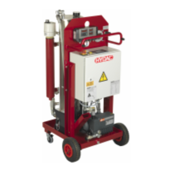
Page 23: Dimensions - Mobile Unit
Dimensions – mobile unit Dimensions – mobile unit en(us) FAM 5 Page 23 / 114 BEWA FAM5 4166129 en-us 2016-07-28 te.doc 2016-07-28... -
Page 24: Hydraulic Circuit
Hydraulic circuit Hydraulic circuit Luftauslass Air outlet Entleerung 3.37 Drain Lufteinlass Entlüftung 8.0* Vent Air intake 3.73 4.70 Entleerung 3.68 Drain 3.43 4.54 Alarm 3.38 Max. 5.0* Min. 12.0* Entleerung Drain 6.23 3.85 4.02 1.04 Einlass Auslass Entleerung Inlet Outlet Drain Optionale Bauteile x.x*... -
Page 25: Working Principle Of Fam
Working principle of FAM 3.85 3/2-directional control valve Motor pump assembly 4.02 Suction strainer 4.54 Flow divider 4.70 Orifice ContaminationSensor CS (optional) Fluid filter for separating solid particles OLF5 6.23 Non-return valve Vacuum pump Heater (optional) 12.0 AquaSensor AS (optional) Working principle of FAM After you switch on the FAM, the motor pump assembly (4.0), depending on the fill level in the vacuum column, starts to suck either from the vacuum... -
Page 26: Possible Applications
Working principle of FAM oil. A value of 0% would indicate water-free oil and 100% would mean oil that is completely saturated with water. Once the STOP button is pressed, the unit runs until the "Min" fill level in the vacuum column is reached. -
Page 27: Fam Set-Up And Connection
FAM set-up and connection FAM set-up and connection Setting up the FAM CAUTION Danger of tipping on inclines Crushing hazard Operate the power unit only on an even, ► level surface. Do not set the unit down on an inclined ►... -
Page 28: Notes On Pipes And Hoses
FAM set-up and connection Air coming out of the vacuum pump can contain particles of vacuum pump oil and/or the fluid. Depending on the composition of the oil and the composition of the gas, there is a danger of damage to health if the emergent gas is inhaled over an extended period of time. - Page 29 FAM set-up and connection The pressure differential in a hydraulic line ( ∆ P ) depends on the (line) following: • flow rate • kinematic viscosity • Pipe dimensions • Fluid density The pressure loss in straight pipes ( ∆ P ) can be calculated as follows: (line) Δp(line) ≈...
-
Page 30: Connecting The Inlet (In)
FAM set-up and connection Connecting the inlet (IN) NOTICE Moving unsecured hoses / lances in the tank The hoses/lances fall out of the tank Attach the hoses/lances to the tank and secure them against falling ► out. NOTICE Contamination in the medium too high The FAM will be damaged Do not prime directly at the bottom of the tank ►... -
Page 31: Connect Outlet (Out)
FAM set-up and connection Connect outlet (OUT) NOTICE Moving unsecured hoses / lances in the tank The hoses/lances fall out of the tank Attach the hoses/lances to the tank and secure them against falling ► out. NOTICE The out connection is closed The unit will be destroyed Check to be sure that all of the locking fixtures at the inlet/outlet are in ►... -
Page 32: Check Air Outlet Of The Vacuum Pump
FAM set-up and connection Check air outlet of the vacuum pump NOTICE Clogged air outlet of the vacuum pump The vacuum pump will be destroyed Before each startup, check the air outlet of the vacuum pump for ► possible clogging. Before each startup, remove the screw plug or other clogs at the air ►... -
Page 33: Check Direction Of Rotation
FAM set-up and connection Compare the voltage and frequency specifications on the FAM nameplate with the existing network specifications. Protect the feed-line to the FAM by using automatic fuses with triggering characteristic "C". Check direction of rotation Check the direction of rotation of the motor by switching it on briefly (jog mode). -
Page 34: Operating Elements On The Fam
Operating elements on the FAM Operating elements on the FAM The following operating elements can be found on the FAM: Item Designation 3.37 Underpressure display 3.48 Ball valve for emptying the vacuum column 3.68 Needle valve to set the pressure in the vacuum column 7.27 Ball valve for emptying the vacuum pump Heater thermostat (optional) - Page 35 Operating elements on the FAM The control and display elements on the switch box have the following functions: Item Control/display Function/designation element Main switch -> Main switch and emergency off Signal lamp -> Alarm signal lamp (yellow) Control panel -> START/STOP Selects operating mode Manual operation for manual activation of...
-
Page 36: Starting Up The Unit
Starting up the unit Starting up the unit NOTICE Connection IN/OUT closed The unit will be destroyed Check to be sure that all of the locking fixtures at the inlet/outlet are in ► "open" position each time before start-up. Switching on the FAM NOTICE Do not press any buttons during boot-up Unintended actions... -
Page 37: Fam Start Screen (Home) And Menu Layout
Starting up the unit FAM start screen (HOME) and menu layout The FAM start screen (HOME) will be displayed if the unit was booted up without error. READY Dewater until Filter until Heat START OM MAN. SET The controls consist of the four function keys (4, 5, 6, 7), the ESC key (8), an ENTER key (9) and four arrow keys (10). -
Page 38: Starting Operation Of The Fam
Starting up the unit cursor and change parameters Starting operation of the FAM Check all hydraulic and electrical connections of the power unit in accordance with the Operation and maintenance Instructions enclosed with the FAM. After switch-on, the most recently selected operating mode will be shown in the READY display. - Page 39 Starting up the unit The vacuum pump starts up and the motor pump assembly starts suction IN OPERATION either from the tank or the +13.0 %S +37.4°C vacuum column, Dewater until depending on the fill level Filter until in the vacuum column. Heat (NO) STOP...
-
Page 40: Setting The Pressure In The Vacuum Column
Starting up the unit Setting the pressure in the vacuum column Set the pressure in the vacuum column with the needle valve (3.68) and check the vacuum using pressure gauge (3.37). Note that the pressure to be set in the vacuum column is dependent, for example, on the operating medium, the operating viscosity, the air or the water content. - Page 41 Starting up the unit • Be on the alert for foam formation and function problems, particularly with high-viscosity media and operating media with high air and water content. Lower pressure (e.g., -0.6 bar) means lower residual water content. Higher pressure (e.g., -0.4 bar) means faster dewatering, especially with free water. By closing the needle valve (D) you reduce the absolute pressure and also the air-flow rate for dewatering the operating medium.
-
Page 42: Pressure Information In The Vacuum Range
Starting up the unit Pressure information in the vacuum range Vacuum Absolute Absolute Relative Relative pressure pressure (gauge) (gauge) mbar mbar … … … … 5000 4000 4000 3000 3000 2000 2000 1000 1000 [8] Atmospheric pressure -100 -0,1 -200 -0,2 -300 -0,3... -
Page 43: Venting The Filter Housing
Starting up the unit Venting the filter housing WARNING Hot fluid Risk of burns Make sure that hot fluid can exit when ► bleeding. NOTICE Air in the fluid filter The filter element is not utilized completely. Bleed the fluid filter after each shut-down/filter element replacement. ►... - Page 44 Starting up the unit Oils with high viscosity Functional issues Set the heater to ≈ 50 °C with an oil viscosity ≥ 350 mm²/sec. ► If the temperature of the operating fluid is raised by 10-20 °C, then the dewatering capacity increases by up to 50 %.
-
Page 45: Stopping Operation Of The Fam
Stopping operation of the FAM Stopping operation of the FAM Press the function key F2 "STOP". The power unit starts the after-run IN OPERATION phase. +13.0 %S +37.4 °C Dewater until Filter until Heat STOP Version with integrated heater: The heater is switched IN OPERATION RESET PHASE off. -
Page 46: Switching Off Fam
Switching off FAM Switching off FAM Once operation is stopped, the unit can be switched off as follows. Close all locking features in the inlet and outlet lines. Switch off the unit using the main switch (position: OFF) Selecting operating mode Press the function key F2 "MODE". -
Page 47: Dewater" Operating Mode (Optional)
Selecting operating mode Change: Move: Done: ENTER 6. Confirm change with ENTER 7. Exit with ESC. NOTICE The operating mode cannot be changed during operation. "Dewater" operating mode (optional) This menu is only displayed when an AquaSensor AS is installed and activated in the Configuration menu. - Page 48 Selecting operating mode OFF: The operating medium is constantly dewatered. Dewater until ON: The operating medium is dewatered until the configured limit for switch-off is reached. The FAM then switches off. • Internal AquaSensor AS: The test interval (see page xx) now starts the time until the FAM switches back on.
-
Page 49: Filter" Operating Mode (Optional)
Selecting operating mode "Filter" operating mode (optional) This menu is only displayed when a ContaminationSensor CS is installed and activated in the Configuration menu. FILTER Filter until HOME Description OFF: The operating medium is constantly filtered. Filter to ON: The operating medium is filtered until the ContaminationSensor CS1000 reaches the configured limit. - Page 50 Selecting operating mode NOTICE The limit for switch-on, "UPPER", must be at least one class higher than the limit for switch-off (LOWER) for each particle size class. Example: UPPER: ISO 20/19/18, LOWER: ISO 19/18/17 Mode 2 (M2) Switching output – Switching output –...
-
Page 51: Contaminationsensor Cs1000 Menu Layout
Selecting operating mode ContaminationSensor CS1000 menu layout o.k. Measuring menu DSPLAY SWtOU switching output o.k. M2 Mode 2 o.k. SP1 switch point o.k. MEAsCH test channel o.k. SAeMAX SAE A-D SAE Class A/B/C/D o.k. ISO 4 ISO class 4µm ISO 6 ISO class 6µm ISO 14 ISO class 14µm... -
Page 52: Setting Times For "Dewater/Filter Until" (Optional)
Selecting operating mode Setting times for "Dewater/Filter until" (optional) INTER- Dewater/filter until: Test interval 00:60h Min. duration 00:10h HOME Description Test interval The amount of time after which the FAM switches back on to check the contamination of the operating media with the operating modes "Dewater until"... -
Page 53: Heat" Operating Mode (Optional)
Selecting operating mode "Heat" operating mode (optional) This menu is only displayed when a heater is installed and activated in the Configuration menu. HEAT Heat HOME Description OFF: The operating medium is not heated. The heater is Heating not in operation. ON: The operating medium is heated up until it reaches the specified target temperature. -
Page 54: Manual Operation
Selecting operating mode Manual Operation In this menu, it is possible to empty the vacuum column and control the individual FAM components manually. Press the function key F3 "MANUAL". READY Dewater until Filter until Heat START MAN. Two submenus are available. -
Page 55: Manually Controlling Components
Selecting operating mode EMPTY After pressing the function key F3 "START", the oil is pumped out of the vacuum column until fill level "Min" is reached in the vacuum column. The unit then runs for a "reset time" of 10 seconds. NOTICE The vacuum column cannot be completely emptied in manual mode since part of the pumped oil returns to the vacuum column through the flow... -
Page 56: Settings - Language, Operating Hours, Program Version
Settings – Language, operating hours, program version Avoid allowing the pumps to run without medium. ► Settings – Language, operating hours, program version Press the function key F4 "SET". READY Dewater until Filter until Heat START MAN. Press on the appropriate function key F3/F4 to change the language. -
Page 57: Loading New Program Version/Language Version
Loading new program version/language version Loading new program version/language version A USB drive with other language versions is included in the scope of delivery. These can also be loaded to the PLC using a micro-SD card, which is also included in the scope of delivery. To do this, load the desired language version from the USB drive to the micro-SD card. -
Page 58: Configuration Menu
Configuration menu The inlet of the card slot is angled on the bottom right side. The cards themselves have a corresponding angled edge. This prevents the cards from being inserted incorrectly. Insert the card into the card edge socket and insert it into the card socket until it clicks into place. -
Page 59: Changing Configuration
Configuration menu Description AS1000 AquaSensor AS1000 detected: detected FAM-5-x-x-x-xx-x-x-S-A/AC/ACS-x CS1000 ContaminationSensor CS1000 detected: detected FAM-5-x-x-x-xx-x-x-S-AC/ACS-x Heater Heater detected: detected FAM-5-x-x-x-xx-x-H-S-x-x The individual components could have the following status: • OFF: Inactive/not detected • ON: Active/detected Changing configuration 1. Press and hold the ESC key. The cursor appears. 2. -
Page 60: Fam Menu Layout
FAM menu layout FAM menu layout HOME - Start Menu START/STOP MODE – Operating mode* DEWATER* External AS ON/OFF Dewater until ON/OFF "Switch-on" limit "Switch-off" limit FILTER* Filter until ON/OFF HEAT* Heat ON/OFF INTERVALS* Test interval MAN – Manual mode Min. -
Page 61: Changing Values And Parameters In Menus
Changing values and parameters in menus Changing values and parameters in menus Change the parameters or values as follows: Press and hold the ESC key. The cursor appears at the top. Use the up ▲ or down ▼ arrow keys to select the desired position Confirm the position with ENTER Switch between ON/OFF with the up Change:... -
Page 62: Network Connection (Ethernet)
Network connection (Ethernet) Network connection (Ethernet) The unit has an open network port on the control panel. This allows the unit to connected to a network via Ethernet or monitored remotely via an integrated web server. Web server DANGER Death or serious injury and/or property damage due to unintentional or unauthorized acces to unit from web server. - Page 63 Network connection (Ethernet) The web server supports the following site languages: • German, English, Italian, French, Spanish Other languages may not be properly displayed on the web server. If the power unit is integrated in a network, then the integrated web server can be accessed via the following IP address.
- Page 64 Network connection (Ethernet) NOTICE • With remote access, the registration process can take several seconds. • In case the registration fails, please press the update key or button in your browser in order to try again. • Access to an individual device can be done simultaneously via multiple web server clients.
- Page 65 Network connection (Ethernet) Make sure to use the exact value shown in the example. Any deviation can result in an error. Click on "OK". The updated parameter is saved. en(us) FAM 5 Page 65 / 114 BEWA FAM5 4166129 en-us 2016-07-28 te.doc 2016-07-28...
-
Page 66: Troubleshooting
Troubleshooting Troubleshooting DANGER Electric shock Danger of fatal injury Any work involving electrical equipment may ► only be done by a properly trained, certified electrician. If an error occurs, the following takes place: • The FAM switches to "ERROR" status •... - Page 67 Troubleshooting No. Function Details Display error number(s) of error(s) currently Page 66 and pending. starting on page Example in window above: #33 = Vacuum column alarm #34 = Dry tray full. NOTE: Errors "12/13", "18/19" and "26/28" are always displayed together. In these cases, it must be determined which error has actually occurred.
-
Page 68: Error Notifications
Troubleshooting 1. Correct error. Information on correcting errors can be found on the following pages. 2. Acknowledge the error on the display by pressing the ENTER key. An error can only be acknowledged when its window is active. 3. Restart power unit. See page 38. NOTICE •... -
Page 69: Empty Vacuum Column
The fault is repeated. -> proceed to Step 10. ->b. The fault is not repeated. -> proceed to Step 11. Contact the HYDAC service department. The fault is repaired. en(us) FAM 5 Page 69 / 114 BEWA FAM5 4166129 en-us 2016-07-28 te.doc... -
Page 70: 04 Vacuum Pump Level Sensor
->b. The cable and plug are not OK. -> proceed to Step 8. Replace the level switch. -> proceed to Step 10. Replace the damaged parts. -> proceed to Step 10. The PLC is defective -> contact the HYDAC Service Department. The fault is repaired. en(us) FAM 5 Page 70 / 114 BEWA FAM5 4166129 en-us 2016-07-28 te.doc... -
Page 71: 05 Vacuum Column Sensor
->b. The cable and plug are not OK. -> proceed to Step 8. Replace the level switch. -> proceed to Step 10. Replace the damaged parts. -> proceed to Step 10. The PLC is defective -> contact the HYDAC Service Department. The failure is repaired. en(us) FAM 5 Page 71 / 114 BEWA FAM5 4166129 en-us 2016-07-28 te.doc... -
Page 72: 12 Measured As Temp Value/13 Measured As %S Value
The fault is repeated. -> proceed to Step 5. ->b. The fault is not repeated. -> proceed to Step 13. Contact the HYDAC service department. The fault is repaired. en(us) FAM 5 Page 72 / 114 BEWA FAM5 4166129 en-us 2016-07-28 te.doc... -
Page 73: 18 H Pump Motor Protection Switch/19 V Pump Motor Protection Switch V-Pump
Troubleshooting When defective, the AquaSensor can be deactivated from the Configuration menu and the unit can continue operation. See page 58. 18 H pump motor protection switch/19 V pump motor protection switch V-pump Trigger for the The motor protection switch has tripped, due to an message: overload in the motor-pump group. -
Page 74: 23. Filter Clogged
The test resulted in no errors. -> proceed to Step 12. ->b. The errors found were -> proceed to Step 6. eliminated. The PLC is defective -> contact the HYDAC Service Department. en(us) FAM 5 Page 74 / 114 BEWA FAM5 4166129 en-us 2016-07-28 te.doc... -
Page 75: 24. V Pump Min
Troubleshooting The fault is repaired. 24 V pump min. Trigger for the The "Min." switch point in the oil tank of the rotary vane message: vacuum pump has been reached. The unit switches to the reset phase and switches off. Notification only displays for FAM-5-x-x-x-xx-R-x-x-x-. -
Page 76: 26. Heater Thermostat
Troubleshooting The fault is repaired. If the error occurs again despite sufficient vacuum pump oil in the rotary vane vacuum pump, check the float switch and then the PLC. 26 Heater thermostat Trigger for the The safety thermostat trips during operating mode with message: heater. -
Page 77: 28 Heater Motor Protection Switch
Troubleshooting Put the cover on. Attach the cover by screwing in the two screws. Attach the setting switch of the heater onto the shaft from above. Note that the adjustment switch only fits one way onto the shaft. Switch the unit on using the main switch and start operation by pressing the F1 key. - Page 78 -> proceed to Step 14. ->b. The fault is not repeated. -> proceed to Step 15. Contact the HYDAC service department. The fault is repaired. When defective, the heater can be deactivated from the Configuration menu and the unit can continue operation. See page 58.
-
Page 79: 32. Fill Column
The fault is repeated. -> proceed to Step 9. ->b. The fault is not repeated. -> proceed to Step 8. The fault is repaired. Contact HYDAC Service. en(us) FAM 5 Page 79 / 114 BEWA FAM5 4166129 en-us 2016-07-28 te.doc 2016-07-28... -
Page 80: 33. Vacuum Column Alarm
Check the pressure in the -> Reduce the vacuum, e.g., vacuum column. See page 40. from -0.6 bar to -0.4 bar. If the error occurs again, contact HYDAC Service. en(us) FAM 5 Page 80 / 114 BEWA FAM5 4166129 en-us 2016-07-28 te.doc... -
Page 81: 34 Drip Tray Full
Troubleshooting 34 Drip tray full Trigger for the The float switch in the tray was actuated. message: The unit stops immediately. Remedy: Perform the following steps: Description Message: 34. Drip tray full Empty the drip tray on the FAM. Check the FAM for any leaks and eliminate any that are found. Acknowledge the error. -
Page 82: Performing Maintenance
Performing maintenance Performing maintenance WARNING FAM in operation Danger of bodily injury Switch off the unit before any maintenance ► work.See page 43 for details. The safety of all persons coming into contact with the FAM and the availability of the unit for use are dependent on regular servicing and maintenance. - Page 83 Performing maintenance Check the fault signal lamps Change Air filter Cleaning the suction strainer Check the AquaSensor Check the float switch in the oil pan 104 Vacuum pump Replace the active carbon filter cartridge (accessory) Rotary vane vacuum pump FAM- 5-x-x-x-xx-R-x-x-x-x Checking the oil level Replace the oil and air de-oiling...
- Page 84 Performing maintenance Main Filter Changing filter element Heater (Option) Check that the connectors are in contact and tight Clean the heating element Synchronize the electricity consumption of the heater by comparing the current values with those on the type label. (optional) Electric System Check the cable conduits for damage...
-
Page 85: Check Fault Signal Lamps
Performing maintenance Check fault signal lamps To check the fault signal lamp (2), switch on the FAM using the main switch. The "Fault" signal lamp then lights up. Change Air filter Replace the air filter (3.73) every six months. If the FAM is in a very dusty/damp environment, the replacement intervals shorten accordingly. -
Page 86: Rotary Vane Vacuum Pump Fam-5-X-X-X-Xx-R-X-X-X-X
Performing maintenance If the vacuum pump has an active carbon filter cartridge at the air inlet, it should be replaced every six months. The active carbon filter cartridge absorbs oil vapors and odors from the exhaust air. Replace the active carbon filter cartridge sooner if exhaust air quality has noticeably worsened. -
Page 87: Checking The Oil Level
To fill up the vacuum pump, proceed as described on page 88. You may only use synthetic vacuum pump oil in accordance with DIN 51506, Group VDL, ISO VG100 when topping up. Vacuum pump oil is available from HYDAC under the following part no.: Description Part no.:... -
Page 88: Filling/Refilling Vacuum Pump Oil
Performing maintenance Filling/Refilling vacuum pump oil WARNING Hot surfaces Risk of burns Keep away from hot surfaces. ► Allow the vacuum pump to cool down before ► performing any work. Proceed as follows to fill the vacuum pump: Switch the unit off at the main switch and unplug the power connector. - Page 89 Performing maintenance Fill the vacuum pump with vacuum pump oil VE 101 via the filler neck (a). Check the oil level through the inspection glass (d). Fill the vacuum pump to no higher than the "Max." mark. Insert the level sensor into the vacuum pump from above.
-
Page 90: Emptying The Vacuum Pump
Performing maintenance Emptying the vacuum pump WARNING Hot surfaces Risk of burns Keep away from hot surfaces. ► Allow the vacuum pump to cool down before ► performing any work. To empty the vacuum pump, proceed as follows: Switch the unit off at the main switch and unplug the power connector. -
Page 91: Changing The Vacuum Pump Oil
Performing maintenance Screw the screw plug back into the drain fitting. The filter element is to be disposed of in an environmentally correct manner. 10. Emptying the vacuum pump is complete. Changing the vacuum pump oil The first oil change must take place after 100 operating hours. Afterwards, the interval increases to ≈... -
Page 92: Replacing The Air De-Oiling Element Of The Vacuum Pump
Performing maintenance Replacing the air de-oiling element of the vacuum pump Oil mist or increased electricity consumption by the drive engine (response of the engine protection switch) are signs of a soiled air de-oiling element. To perform these tasks, you will need the following tools and equipment: •... -
Page 93: Dry-Running Rotary Vane Vacuum Pump Fam-5-X-X-X-Xx-Rd-X-X-X-X
Performing maintenance Dry-running rotary vane vacuum pump FAM-5-x-x-x-xx-RD-x-x-x-x The vacuum pump comes with the following components: Item Designation Direction of rotation Minimum height Angled vane side Housing hole Housing cover Rotor Body 4x vane* Filter cartridge* Filter chamber Seal* Seal* screws * In maintenance kit, see page 107. -
Page 94: Replacing The Filter
Performing maintenance Since wear depends greatly on operating conditions, and replacement may be necessary sooner under extreme conditions, we recommend inspecting the vanes after 4,000 operating hours. Replacing the filter 1. Unscrew the housing cover (b). 2. Remove the filter cartridge (f) with seals (m, n) from the filter chamber (g). -
Page 95: Inspecting/Replacing Vanes
Performing maintenance Inspecting/replacing vanes 1. Unscrew the housing cover (b) from the housing. 2. Remove the vanes (e) for inspection. All vanes should have a min. height (X): Item Minimum height 12 mm NOTICE All of the vanes should be replaced at the same time. If the min. -
Page 96: Clean The Suction Screen
Performing maintenance Clean the suction screen NOTICE Operation without a suction strainer The pump will be destroyed The unit may not be operated without the suction strainer. ► Clean the suction screen regularly. ► To protect the pump from coarse contamination particles and other foreign bodies, a dirt trap with a strainer insert is fitted at the pump inlet. - Page 97 Performing maintenance Switch off the FAM at the main switch and close the shut-off valve at the inlet and outlet in order to prevent the oil from flowing back out of the tank. Make sure that the unit cannot be inadvertently switched back on during maintenance work.
- Page 98 Performing maintenance Remove (2) the filter element from the filter bowl by turning slightly (1). Clean the inside of the filter bowl of dirt and deposits. Check the O-ring on the filter bowl for damage. Replace it if necessary. Moisten the O-ring on the filter bowl with the operating medium.
- Page 99 Performing maintenance Turning it slightly, press the new filter element down into the mount on the filter bowl. 10. Push the filter bowl with the filter element up into the mount on the filter head. 11. Push the housing clamp (1) up around the filter bowl over the bead on the filter bowl / filter head.
- Page 100 Performing maintenance 12. Check that the drain plug on the filter bowl is secure. 13. The filter element change is now complete. Bleed the filter housing as described on page 43. After commissioning, check the filtration unit for leaks. en(us) FAM 5 Page 100 / 114 BEWA FAM5 4166129 en-us 2016-07-28 te.doc...
-
Page 101: Heater Maintenance (Optional)
Performing maintenance Heater maintenance (optional) WARNING Hot surfaces Risk of burns Allow the heater to cool down before ► performing any work. The use of different oils can lead to a build-up of a layer of film on the heating element. - Page 102 12. Check the heating element for overheating. This can be seen in a bent heater core or sheath and in crack formations. If required, replace the heating element or the sheath. Contact HYDAC in this regard. 13. As a seal, wrap Teflon tape around the connecting thread on the heating element.
-
Page 103: Emptying The Heater
Performing maintenance 19. Plug the mains plug or connect the FAM up to the main electricity supply. 20. Switch on the FAM at the main switch and start the unit by pressing the on switch. 21. Check the heater for any leaks while in operation. 22. -
Page 104: Checking The Aquasensor As1000
Emptying the heater is now complete. Checking the AquaSensor AS1000 Check the AquaSensor annually with the calibration and adjustment set. This can be acquired from HYDAC under item no. 3122629. You can find further information in the calibration and adjustment set instruction manual. - Page 105 Performing maintenance The function of the float switch is thus ensured and the check has been successfully completed. en(us) FAM 5 Page 105 / 114 BEWA FAM5 4166129 en-us 2016-07-28 te.doc 2016-07-28...
-
Page 106: Spare Parts
Spare parts Spare parts Make sure to indicate the entire unit designation from the unit designation and the serial number when ordering spare parts. Qty. Designation p/no. Breather filter 0080 MG 020 300873 Motor pump assembly Complete suction strainer G1", 635624 consisting of: 1x strainer insert, 250µm... -
Page 107: Dry-Running Rotary Vane Vacuum Pump Fam-5-X-X-X-Xx-Rd-X-X-X-X
Regular inspection and maintenance work is indispensable for ensuring trouble-free operation and long service life for your FluidAqua Mobil. Our HYDAC Servicenter offers you these tasks within agreed-upon time frames and at fixed prices. HYDAC SERVICE GMBH Friedrichstaler Straße 15a, Werk 13... -
Page 108: Disposing Of The Unit
Disposing of the unit Store the unit in a clean, dry (non-condensing) space. Observe the storage temperature range of 0–40 °C. Disposing of the unit Please dispose of the packaging material in an environmentally friendly manner. After dismantling the unit and separating the various materials, dispose of the unit in an environmentally-friendly manner. - Page 109 Technical data Permissible 15 … 350 mm²/s (without integrated heater) Operating viscosity range ** 15 ... 550 mm²/s (with integrated heater) Permissible viscosity range for 15 … 200 mm²/s - with technical the particle measurement measurement equipment (ACS) Fluid temperature range** 10 to 80 °C / 50 to 176 °F Ambient temperature ** 10 to 40 °C / 32 to 104 °F...
-
Page 110: Connection Overview
Connection overview Connection overview Item FAM 5 1 FAM inlet connector 42L/M52x2 (external thread)* 2 adapter Adapter G1 ½ A (external thread)** 3 FAM outlet connector 28L/M36x2 (external thread)* 4 adapter Adapter G1 A (external thread)** 5 Suction hose connection 42L/M52x2 (internal thread)*** 6 adapter Adapter G1 ½... -
Page 111: Model Code
Model code Model code - M - - Z - 1 / Product FluidAqua Mobil Filter Size ≈ 5 l/min Operating fluid Mineral oil – NBR seals, checked with mineral oil* Insulation oil – NBR seals, checked with insulation oil* HFD-R phosphoric acid ester fluids –... -
Page 112: Ec Declaration Of Conformity
EC declaration of conformity EC declaration of conformity HYDAC FILTER SYSTEMS GMBH Postfach 12 51 66273 Sulzbach / Saar Deutschland Industriegebiet 66280 Sulzbach / Saar Deutschland Telephone: ++49 (0) 6897 509 01 Internet: www.hydac.com EC declaration of conformity We hereby declare that the following designated product, on the basis of its design and construction, and in the version which we have brought to market, corresponds to the fundamental safety and health requirements contained in the standards listed below. - Page 114 HYDAC FILTER SYSTEMS GMBH Industriegebiet Postfach 1251 66280 Sulzbach/Saar 66273 Sulzbach/Saar Germany Germany Phone: +49 (0) 6897 509 01 Central Fax: +49 (0) 6897 509 9046 Technical Department Fax: +49 (0) 6897 509 577 Sales Department Internet: www.hydac.com E-mail: filtersystems@hydac.com...
Need help?
Do you have a question about the FAM 5 FluidAqua Mobil and is the answer not in the manual?
Questions and answers