Table of Contents
Advertisement
Quick Links
Advertisement
Table of Contents

Related Manuals for SMART Embedded Computing PCIE-7217

Summary of Contents for SMART Embedded Computing PCIE-7217
- Page 1 PCIE-7217 Installation and Use P/N: 6806873A01B October 2019...
- Page 2 Computing” and the SMART Embedded Computing logo are trademarks of SMART Modular Technologies, Inc. All other names and logos referred to are trade names, trademarks, or registered trademarks of their respective owners. These materials are provided by SMART Embedded Computing as a service to its customers and may be used for informational purposes only. Disclaimer* SMART Embedded Computing (SMART EC) assumes no responsibility for errors or omissions in these materials.
-
Page 3: Table Of Contents
Unpacking and Inspecting the PCIE-7217 Card ....... . . 45... - Page 4 4.2.1 PCIE-7217 Face Plate View........
- Page 5 Related Documentation ............105 A.1 SMART Embedded Computing Documentation ....... . 105...
- Page 6 Table of Contents PCIE-7217 Installation and Use (6806873A01B)
- Page 7 PCIE-7217 Block Diagram ........
- Page 8 Table of Contents PCIE-7217 Installation and Use (6806873A01B)
- Page 9 SMART EC Documentation ......... . . 105 PCIE-7217 Installation and Use (6806873A01B)
- Page 10 List of Tables PCIE-7217 Installation and Use (6806873A01B)
-
Page 11: About This Manual
Functional Description on page 53 provides information about the functional blocks in the PCIE-7217 card block diagram. Controls, Indicators, and Connectors on page 59 provides information about the controls, indicators, connectors, and pin assignments associated with the PCIE-7217 card. - Page 12 ElectroStatic Discharge ESSD ElectroStatic Sensitive Device FUF Command-line Utility Firmware Upgrade Facility GaaS Gaming-as-a-Service Graphics Processing Unit JTAG Joint Test Action Group High Definition Light Emitting Diode Low Pin Count Least Significant Byte mCPU Management CPU PCIE-7217 Installation and Use (6806873A01B)
- Page 13 Small Outline Dual In-Line Memory Module Serial Presence Detect Serial Peripheral Interface Solid State Device SVID Serial Voltage Identification Test Clock Test Data Output UEFI Unified Extensible Firmware Interface Universal Serial Bus Virtual Function Virtual Machine PCIE-7217 Installation and Use (6806873A01B)
- Page 14 Ranges, for example: 0..4 means one of the integers 0,1,2,3, and 4 (used in registers) Logical OR Indicates a hazardous situation which could result in death or serious injury Indicates a hazardous situation which may result in minor or moderate injury PCIE-7217 Installation and Use (6806873A01B)
- Page 15 Indicates an electrical situation that could result in moderate injury or death Indicates that when working in an ESD environment care should be taken to use proper ESD practices No danger encountered, pay attention to important information PCIE-7217 Installation and Use (6806873A01B)
- Page 16 This manual has been revised and replaces all prior editions. Part Number Publication Date Description Re-brand to SMART Embedded Computing. Updated English and German safety notes; added French safety notes section. Updated operating temperature and power requirements in Section 2.3. Added Section 6.3 for Windows information.
-
Page 17: Safety Notes
Failure to comply with these precautions or with specific warnings elsewhere in this manual could result in personal injury or damage to the equipment. SMART Embedded Computing intends to provide all necessary information to install and handle the product in this manual. Because of the complexity of this product and its various uses, we do not guarantee that the given information is complete. - Page 18 Operating the product without forced air cooling may lead to overheating and product damage. When operating the product in areas of electromagnetic radiation, secure the product in the system using the front panel screws. Make sure the product is fully shielded by the enclosure. PCIE-7217 Installation and Use (6806873A01B)
- Page 19 Before installing or removing an additional device or module, read the respective documentation. Incorrect installation of the product can cause damage to the product. Use appropriate tools when installing or removing the card to avoid damaging the card. PCIE-7217 Installation and Use (6806873A01B)
- Page 20 During handling, shipping, and assembly, it is possible that pins, mounting screws, fans, and other items became loose or damaged. Do not operate a damaged system, as it may damage the devices that interface with the system. PCIE-7217 Installation and Use (6806873A01B)
- Page 21 Power Feed Short Circuits or Personal Injury Make sure that all power feeds to the chassis are not energized. Be careful with the tools used to prevent a short circuit. PCIE-7217 Installation and Use (6806873A01B)
- Page 22 Always use the same type of lithium battery as is installed and make sure the battery is installed as described in the manual. Data Loss Installing another battery type than the one mounted at product delivery may cause data loss. PCIE-7217 Installation and Use (6806873A01B)
- Page 23 PCB or the battery holder. Environment Environmental Damage Improper disposal of used products may harm the environment Always dispose of used products according to your country’s legislation and manufacturer’s instructions. PCIE-7217 Installation and Use (6806873A01B)
- Page 24 Safety Notes Safety Notes PCIE-7217 Installation and Use (6806873A01B)
-
Page 25: Notice De Sécurité
à ces précautions ou aux avertissements spécifiques contenus ailleurs dans ce manuel, peut engendrer des lésions corporelles ou dommages à l’équipement. SMART Embedded Computing prévoit dans ce manuel de fournir toute l’information nécessaire pour installer et manipuler le produit. En raison de la complexité de ce produit et de ses diverses utilisations, nous ne pouvons pas garantir que les informations fournies sont complètes. - Page 26 Une humidité élevée et la condensation sur la surface du produit crée des courts-circuits. N’opérez pas le système en dehors des limites environnementales spécifiées. Assurez-vous que le système soit complètement sec et qu'il n'y ait pas d'humidité sur aucune surface, avant de mettre sous tension PCIE-7217 Installation and Use (6806873A01B)
- Page 27 Avant de toucher au produit, assurez-vous que vous travaillez dans un environnement exempt de décharge électrostatique. Tenez le produit par ses extrémités et ne touchez aucune composante ou circuit. Zone d'accès Restreint Installez le système uniquement dans une zone d’accès restreint. PCIE-7217 Installation and Use (6806873A01B)
- Page 28 Si le support est équipé de dispositifs de stabilisation, assurez-vous qu'ils sont installés et déployés de façon à ce que le support soit sécurisé. Ensuite, procédez au montage ou à la maintenance du système. PCIE-7217 Installation and Use (6806873A01B)
- Page 29 Le port intra-bâtiment de l'équipement ou du sous-ensemble NE DOIT PAS être relié métalliquement à des interfaces qui se connectent à l'installation extérieure (OSP) ou à son filage. Ces interfaces sont conçues pour être utilisées uniquement comme PCIE-7217 Installation and Use (6806873A01B)
- Page 30 (ou les deux) et peut être nocif pour les yeux. Recherchez de l’information supplémentaire (puissance, longueur d'onde, visibilité, durée d'impulsion, normes applicables) avant de faire le maintien de l'équipement. Ne regardez jamais un appareil laser avec un instrument optique. PCIE-7217 Installation and Use (6806873A01B)
- Page 31 PCB ou le support de batterie. Environnment Dommage Environnemental Une disposition impropre des produits usagés peut être nocif pour l’environnement. Éliminez les produits usagés toujours conformément à la législation de votre pays et aux instructions du fabricant. PCIE-7217 Installation and Use (6806873A01B)
- Page 32 Notice de Sécurité Notice de Sécurité PCIE-7217 Installation and Use (6806873A01B)
-
Page 33: Sicherheitshinweise
Verletzungen oder Schäden am Produkt zur Folge haben. SMART Embedded Computing ist darauf bedacht, alle notwendigen Informationen zum Einbau und zum Umgang mit dem Produkt in diesem Handbuch bereit zu stellen. Da es sich jedoch um ein komplexes Produkt mit vielfältigen Einsatzmöglichkeiten handelt, können wir die Vollständigkeit der im Handbuch enthaltenen Informationen nicht... - Page 34 Hohe Luftfeuchtigkeit und Kondensat auf der Oberfläche des Produktes können zu Kurzschlüssen führen. Betreiben Sie das Produkt nicht außerhalb der angegebenen Grenzwerte. Stellen Sie sicher, dass das Produkt vollständig trocken ist und keine Feuchtigkeit auf der Oberfläche ist, bevor Sie den Strom einschalten. PCIE-7217 Installation and Use (6806873A01B)
- Page 35 Bevor Sie Karten berühren, vergewissern Sie sich, dass Sie in einem ESD-geschützten Bereich arbeiten. Fassen Sie Karten nur an der Seite an und berühren Sie keine elektronischen Komponenten. Bereich mit eingeschränktem Zugang Installieren Sie das Board in ein System nur in Bereichen mit eingeschränktem Zugang. PCIE-7217 Installation and Use (6806873A01B)
- Page 36 Schaltschrank mit Kippsicherungen ausgestattet ist, stellen Sie sicher, dass diese auch installiert und ausgefahren sind, um einen sicheren Stand des Schranks zu gewährleisten. Beginnen Sie erst danach mit dem Einbau oder der Wartung des Systems. PCIE-7217 Installation and Use (6806873A01B)
- Page 37 CORE) der Geräte oder Baugruppen sind nur für gebäudeinterne Verkabelung vorgesehen. Die Schnittstellen sind als Typ 2 oder Typ 4 definiert (wie in GR-1089-Core beschrieben) und erfordern eine Isolation zu Leitungen außerhalb des Gebäudes. Die PCIE-7217 Installation and Use (6806873A01B)
- Page 38 Wenn ein Etikett mit der Aufschrift CLASS 1 LASER PRODUCT auf Ihrem System angebracht ist, ist das Gerät mit einem Lasergerät ausgestattet. Diese Geräte enthalten ein Lasersystem, das sichtbare oder unsichtbare Laserstrahlung (oder beides) erzeugt und für die Augen schädlich sein kann. PCIE-7217 Installation and Use (6806873A01B)
- Page 39 Wenn Sie die Batterie mit einem Schraubenzieher ausbauen, können das PCB und die Batteriehalterung beschädigt werden. Umweltschutz Umweltschäden Unsachgemäße Entsorgung von gebrauchten Produkten kann die Umwelt schädigen. Entsorgen Sie gebrauchte Produkte stets gemäß der in Ihrem Land gültigen Gesetzgebung und den Empfehlungen des Herstellers. PCIE-7217 Installation and Use (6806873A01B)
- Page 40 Sicherheitshinweise Sicherheitshinweise PCIE-7217 Installation and Use (6806873A01B)
-
Page 41: Introduction
The PCIE-7217 is a high density, PCI Express (PCIe) card with two independent CPU complexes which is optimized to provide maximum gaming density for Gaming-as-a- Service (GaaS) and cloud gaming applications in a carrier data center environment. -
Page 42: Hardware Description
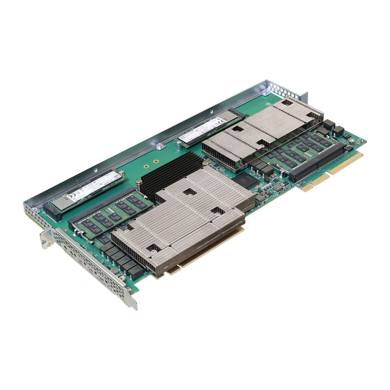
Figure 1-2 Mechanical Layout CPU2 CPU1 Features PCIE-7217 cards are designed specifically for use in the MC4100 shelf and are not compatible with standard PCIe-based systems.The main features of the PCIE-7217 card include: PCIe full length, extended full height card (312mm x 159.6mm x 22.86mm) ... -
Page 43: Software Overview
The software is delivered in the form of software components. These software components contain necessary binaries, utilities, and tools to enable the PCIE-7217 card function as a management CPU (mCPU) or an application CPU (aCPU) for upgrading firmware and for media transcoding. -
Page 44: Standard Compliances
Annex II to Directive 2011/65/EU) substances in electrical and electronic equipment (RoHS) Ordering and Support Information Refer to the data sheet for the PCIE-7217 for a complete list of available variants and accessories. Refer to Appendix A, Related Documentation on page 105 or consult your local SMART EC sales representative for the availability of other variants. -
Page 45: Hardware Preparation And Installation
Chapter 2 Hardware Preparation and Installation Overview This chapter provides information on unpacking and inspecting the PCIE-7217 card along with procedures and safety precautions to follow while handling the card. The environmental, thermal, and power requirements, and the installation and removal procedures of the card are also explained in this chapter. -
Page 46: Environmental, Thermal, And Power
High humidity and condensation on the card surface causes short circuits. Do not operate the card outside the specified environmental limits. Make sure that the card is completely dry and there is no moisture on its surface before applying power. PCIE-7217 Installation and Use (6806873A01B) -
Page 47: Power Requirements
Hardware Preparation and Installation 2.3.2 Power Requirements The next table provides the typical power consumed by the PCIE-7217 card. Table 2-2 Power Requirements Mode PCIe slot power with expansion connector Idle Active 200W Peak 230W Idle: Both CPUs at Linux login prompt. -
Page 48: Esd Prevention
Necessary precautions must be followed to keep the card stable to avoid damage to the card. For more information about securing the PCIe card in a Appendix A, Related server, refer to the product documentation listed in Documentation on page 105 PCIE-7217 Installation and Use (6806873A01B) -
Page 49: Pcie-7217 Card Installation And Removal
6-32 screw (0.25") is used near the rear panel – M3.0 screw (6mm) is used on the front card guide. 7. Fill the empty PCIe slots adjacent to the PCIE-7217 with other PCIe cards or filler cards for optimal cooling. PCIE-7217 Installation and Use (6806873A01B) - Page 50 The CPU transcoding performance is directly related to the airflow and cooling ability of the server in which the card is installed. 8. Connect your system to the console microUSB port of the PCIE-7217 card using a standard USB-A to microUSB-B cable.
-
Page 51: Pcie-7217 Card Removal
3. Remove the 6/32 screw securing the card near the rear panel, and the M3.0 screw on the front card guide and gently pull the PCIE-7217 card from the slot. 4. Place the PCIE-7217 card in an ESD-protective bag and seal it securely. - Page 52 Hardware Preparation and Installation Hardware Preparation and Installation PCIE-7217 Installation and Use (6806873A01B)
-
Page 53: Functional Description
PCIe (x16) Edge Connector MaxCore Edge Connector CPU Complex The CPU complex of PCIE-7217 card is comprised of two Intel Core i7 processors that operate independently in the system. The processor information in this section describes the features and details of a single Intel Core processor. -
Page 54: Processor
Timer functions DDR4 Memory The PCIE-7217 card comes with four DDR4 SO-DIMM slots, two on each processor. Each DIMM is populated with either 8GB or 16GB of memory. That means each processor has an 16GB DDR4 memory (8GB in each slot) running at DDR4-2400 speed, resulting a total 32GB of memory on each PCIE-7217 card. -
Page 55: Storage
PCIE-7217 face plate as a regular USB port to connect USB devices. A second USB2.0 port is only available if the PCIE-7217 is installed in an MC4100 chassis and is selected as the mCPU. In this case, it connects to the MC4100 BMC and supports the Remote Media function. -
Page 56: Real Time Clock
The serial console COM1 of the processor connects to the BMC on the system’s motherboard and provides Serial Over LAN (SOL) access. The PCIE-7217 card provides one USB 2.0 host port per CPU and one USB terminal port to access the serial console (COM port) of the card’s CPUs on its face plate. -
Page 57: Trusted Platform Module
Edge connector 1 provides 3.3V supply to the CPLD and edge connector 2 provides 3.0V RTC power to the PCH1 and PCH2. 3.11 Temperature Sensors There are several temperature sensors on the PCIE-7217 card. Two SPD memory temperature sensor devices are each located in different areas, refer to Figure 3-2 on page 57. -
Page 58: Clock Distribution
PCH. During power up the CPLD state machine drives the reset control to each CPU during an induced reset from the front panel reset switch. For more information about Reset button, refer the section Controls on page PCIE-7217 Installation and Use (6806873A01B) -
Page 59: Controls, Indicators, And Connectors
USB 2.0 CPU2 Console via USB 2.0 CPU1 & CPU2 User LED CPU1 User LED CPU2 The PCIE-7217 card comes with two gold finger edge connectors referred as edge connector 1 and edge connector 2. PCIE-7217 Installation and Use (6806873A01B) -
Page 60: Pci Express Edge Connector
3.3 Volt auxiliary power +3.3V 3.3 Volt power Signal for Link WAKE# PRST# Reset reactivation Mechanical Key RSVD Reserved Ground Ground REFCLK+ Reference clock Tx_P(0) Transmitter Lane 0 REFCLK- Differential pair Tx_N(0) Differential pair Ground PCIE-7217 Installation and Use (6806873A01B) - Page 61 Transmitter Lane 4 RSVD Reserved Tx_N(4) Differential pair Ground Ground Rx_P(4) Receiver Lane 4 Ground Rx_N(4) Differential pair Tx_P(5) Transmitter Lane 5 Ground Tx_N(5) Differential pair Ground Ground Rx_P(5) Receiver Lane 5 Ground Rx_N(5) Differential pair PCIE-7217 Installation and Use (6806873A01B)
- Page 62 Transmitter Lane 10 Ground Tx_N(10) Differential pair Ground Ground Rx_P(10) Receiver Lane 10 Ground Rx_N(10) Differential pair Tx_P(11) Transmitter Lane 11 Ground Tx_N(11) Differential pair Ground Ground Rx_P(11) Receiver Lane 11 Ground Rx_N(11) Differential pair PCIE-7217 Installation and Use (6806873A01B)
- Page 63 Ground Ground Rx_P(14) Receiver Lane 14 Ground Rx_N(14) Differential pair Tx_P(15) Transmitter Lane 15 Ground Tx_N(15) Differential pair Ground Ground Rx_P(15) Receiver Lane 15 PRSNT#2 Hot plug present detect Rx_N(14) Differential pair RSVD#2 Reserved Ground PCIE-7217 Installation and Use (6806873A01B)
-
Page 64: Maxcore™ Expansion Edge Connector
UART1 receiver of PCH2 GND Ground EXT_RXD PCH1_UART1_EXT_ UART1 transmitter Ground of PCH1 PCH1_UART1_EXT_ UART1 receiver of Ground PCH1 PCH2_USB2_B USB port of PCH2 Ground MC_DP PCH2_USB2_B Differential pair Ground MC_DM PCH1_USB2_BMC_ Ground USB port of PCH1 PCIE-7217 Installation and Use (6806873A01B) - Page 65 Reference Clock of PCH2 GND Ground PCH2_CLK_10 0M_REFCLK_D Differential pair Ground PCH1_100M_REFCL Reference Clock of Ground K_DP PCH1 PCH1_100M_REFCL Ground Differential pair K_DN CON_EXT_PR PCIe edge present input Ground SNT_N Mechanical Key Not connected Not connected PCIE-7217 Installation and Use (6806873A01B)
-
Page 66: Table 4-2 Maxcore Expansion Edge Connector 2 Pinout
LPC Frame of PCH1 LPC Port of PCH1 bus PCH1_LPC_LA PCH1_SERIRQ LPC Interrupt signal PCH1_LPC_LA PCH_SKL1_PLTRST LPC reset signal Ground Ground PCH2_USB2_I PCH1_CLKOUT_LP USB2 port of PCH2 LPC clock of PCH1 OMOD_DP PCH2_USB2_I Differential pair Ground OMOD_DM PCIE-7217 Installation and Use (6806873A01B) - Page 67 PCH2_SATA0_ Ground RX_D_P SATA0receiver port of PCH2 (Diff pair) PCH2_SATA0_ Ground RX_D_M PCH2_SATA0_TX_D SATA0 transmitter Ground port of PCH2 (Diff pair) PCH2_SATA0_TX_D Ground PCH1_P2E_EX Ground T_RX_D_P PCIe receiver of PCH1 (Diff pair) PCH1_P2E_EX Ground T_RX_D_M PCIE-7217 Installation and Use (6806873A01B)
- Page 68 SATA0 receiver port of PCH1 (Diff pair) PCH1_SATA0_ Ground RX_D_M PCH1_SATA0_TX_D Ground SATA0 transmitter port of PCH1 (Diff PCH1_SATA0_TX_D pair) Ground Not connected Ground Not connected Ground Ground Not connected Ground Not connected CON_MNGR_P Management signal Ground RSNT_N PCIE-7217 Installation and Use (6806873A01B)
-
Page 69: Console Access Port (Usb Slave)
Console Access Port (USB Slave) Pinout Name VBUS Data- Data+ Identification 4.2.5 USB Host Ports The microUSB port is the USB1 port of the PCH. Table 4-4 USB Host Ports Pinout Name VCC 5V Data- Data+ Identification PCIE-7217 Installation and Use (6806873A01B) -
Page 70: Leds
(CPUs off). 4.3.2 On-board SSD Activity LEDs The following figures shows the on-board SSD activity LEDs for CPU1 (D13) and CPU2 (D6). Figure 4-3 Location of On-board SSD Activity LED for CPU1 (D13) (CPU1) PCIE-7217 Installation and Use (6806873A01B) -
Page 71: Figure 4-4 Location Of On-Board Ssd Activity Led For Cpu2 (D6)
Controls, Indicators, and Connectors Figure 4-4 Location of On-board SSD Activity LED for CPU2 (D6) CPU2 CPU1 (CPU2) Table 4-5 On-board SSD Activity LEDs Label Color Status Description Green CPU1 on-board SSD activity Green CPU2 on-board SSD activity PCIE-7217 Installation and Use (6806873A01B) -
Page 72: Ssd Activity Leds
The following figure shows the M.2 SSD activity LEDs for CPU1 (D8) and CPU2 (D7). Figure 4-5 Location of M.2 SSD Activity LEDs (D7 and D8) Table 4-6 M.2 SSD Activity LEDs Label Color Status Description Green CPU1 M.2 SSD activity Green CPU2 M.2 SSD activity PCIE-7217 Installation and Use (6806873A01B) -
Page 73: Face Plate Leds
Blinking Blue CPU power has been toggled Blinking Red On-board power failure Solid Red Processor held in reset state CPU2 Green CPU power UP None CPU power OFF Blinking Blue CPU power has been toggled PCIE-7217 Installation and Use (6806873A01B) -
Page 74: Backplane Ethernet Communication Status/Activity Leds
Figure 4-7 Location of Backplane Ethernet Communication Status LEDs CPU2 CPU1 CPU1 CPU2 Table 4-8 Backplane Ethernet Communication LEDs Label Color Status Description Green Link Up/Activity Green Link 1000 Amber Link 100 Green Link Up/Activity Green Link 1000 Amber Link 100 PCIE-7217 Installation and Use (6806873A01B) -
Page 75: Controls
Controls, Indicators, and Connectors Controls There are two reset buttons available on the face plate of the PCIE-7217 card used to reset PCH1 and PCH2. Button S4 resets PCH1 Button S3 resets PCH2 The following figure shows the location of the reset buttons (S3 and S4) and the switch (S1). - Page 76 Controls, Indicators, and Connectors Controls, Indicators, and Connectors PCIE-7217 Installation and Use (6806873A01B)
-
Page 77: Bios
To access the BIOS Setup screen, press <F2> when the message to enter the BIOS setup appears on the screen. The following figure shows a sample BIOS Setup screen. PCIE-7217 Installation and Use (6806873A01B) -
Page 78: Figure 5-1 Bios Setup Screen
If those values cause the system boot to fail, reboot and enter setup to get the default values or to change the selections that caused the failure. PCIE-7217 Installation and Use (6806873A01B) -
Page 79: Menu Bar
Figure 5-1 screen are used to make selections on-screen or to leave the current menu. The legend keys and their alternate options are explained in Table 5-2. All submenus are indicated by the right-bracket symbol (>). PCIE-7217 Installation and Use (6806873A01B) -
Page 80: Field Help
Moves cursor to next or previous page 5.2.3 Field Help The help text of the selected field is displayed on the right side of the screen. By scrolling through each field, the related help text of the active selection is displayed. PCIE-7217 Installation and Use (6806873A01B) -
Page 81: General Help
Configuring BIOS Setup Settings This section provides BIOS configuration in each of the menu options. 5.3.1 Main Menu Select the Main tab from the menu bar. By default, the Main tab is selected on the BIOS Setup screen. PCIE-7217 Installation and Use (6806873A01B) -
Page 82: Figure 5-3 Main Menu
The next table provides the list of features that can be configured in Main menu. Table 5-3 Main Menu Selection Options/Format Description Language English/French/Chinese/Japanese Set the setup language System Time HH:MM:SS Set the system time System Date MM/DD/YYYY Set the system date PCIE-7217 Installation and Use (6806873A01B) -
Page 83: Advanced Menu
The other configurations shown in the Advanced menu are default values and do not need configuring. Table 5-4 Advanced Menu Feature Description Boot Configuration To select the boot configuration Console Redirection To change console redirection parameter PCIE-7217 Installation and Use (6806873A01B) -
Page 84: Boot Configuration
Figure 5-5 Boot Configuration The following table provides information about options in the Boot Configuration submenu and their default values. NOTICE The values shown in the tables enclosed within brackets [...] indicate the default settings. PCIE-7217 Installation and Use (6806873A01B) -
Page 85: Console Redirection Setup
Figure 5-6 Console Redirection Setup This table provides information about the feature options in the Console Redirection Setup submenu and their defaults values. NOTICE The values shown in the tables enclosed within brackets [...] indicate the default settings. PCIE-7217 Installation and Use (6806873A01B) -
Page 86: Table 5-5 Console Redirection Setup
Selects the flow control XON/XOFF 0 Second 2 Second Selects the information screen display Information Wait Time [5 Second] time 10 Second 30 Second [Yes] Selects if the console redirections is C.R. After Post enabled after Post PCIE-7217 Installation and Use (6806873A01B) -
Page 87: Security Menu
To view the Security menu, select the Security tab from the menu bar. Use the legend keys to make a selection and exit from the Security menu. The Security menu appears as shown in the following figure. Figure 5-7 Security Menu PCIE-7217 Installation and Use (6806873A01B) -
Page 88: Power Menu
Sets the password 5.3.4 Power Menu To view the Power menu, select the Power tab from the menu bar. The Power menu is displayed and looks similar to the following figure. Figure 5-8 Power Menu PCIE-7217 Installation and Use (6806873A01B) -
Page 89: Boot Menu
Dual Boot Type Boot Type Legacy Boot Type Selects the boot type [UEFI Boot Type] [Enabled] Enables or disables the quick boot feature which skip Quick Boot certain tests to decrease the boot time Disabled PCIE-7217 Installation and Use (6806873A01B) - Page 90 Selects the timeout in seconds before the first boot Timeout attempt [Enabled] Selects if another boot devices is used after the first Automatic Failover one failed Disabled Change EFI boot order settings Legacy Change Legacy boot order settings PCIE-7217 Installation and Use (6806873A01B)
-
Page 91: Exit Menu
Exits the setup and saves the changes Save Changes Without Exit Saves the changes without exiting Exit Discarding Changes Exits the setup and discards the changes Load Setup Defaults Loads the default setup parameter Discard Changes Discards all changes performed PCIE-7217 Installation and Use (6806873A01B) -
Page 92: Bios Boot Parameter
# BIOS Setup > Boot > EFI Device First fw_boot_order=[<bootdev>{[,<bootdev>]}] bootdev: full name of a boot option, as it is shown by the BIOS, or one of the following predefined selfspeaking names bpusb0 bpusb1 bpusb2 bpusb3 PCIE-7217 Installation and Use (6806873A01B) -
Page 93: Information For Other Software
Information for Other Software References to software installation and use manuals related to the operating system (OS), Basic Blade Services (BBS) software installation, and firmware upgrades for the PCIE-7217 cards are found in Related Documentation on page 105. PCIE-7217 Installation and Use (6806873A01B) - Page 94 BIOS BIOS PCIE-7217 Installation and Use (6806873A01B)
-
Page 95: Software
This chapter provides the software-related information for the PCIE-7217. Management CPU Software The PCIE-7217 software is based on CentOS 7.x Linux distribution. It runs on both the Management CPU (mCPU) and the Application CPU (aCPU). A service is started on the mCPU, which exposes an interface for you to configure the PCI switch of the MC4100 system. -
Page 96: Disk Installation
10. Execute disk_install.sh -d disk:<storage-device> -i bootusb If you want to install Complete ISO on shelfHost using a bootable USB and also want to setup TFTP server to enable PXEboot for applicationCPUs, use the following command: PCIE-7217 Installation and Use (6806873A01B) -
Page 97: Login
6.2.2 Firmware Upgrade The PCIE-7217 card has two firmware devices that need to be upgraded, when required. The first device is the CPU with the BIOS firmware and the second is the CPLD. The root file system includes the latest firmware images for both the devices and a firmware command-line utility (FCU) to execute the upgrade procedure. -
Page 98: Query Command
#01 Device : pcie7217-cpu Bank #0 - Version: 0.1.00000006 ********************[[[[[ REPORT END ]]]]]******************** The BIOS image has two images inside, the upper is for the first CPU and the other is for the second CPU. PCIE-7217 Installation and Use (6806873A01B) -
Page 99: Upgrade Command
–do-reboot. 2. After the reboot, enter the upgrade command again. FCU uploads the image to the flash. [root@pcie7217-s1-c1 rom]# fcu -uf pcie7217-cpu-1.1.0.fri ****************[[[[[REPORT BEGIN]]]]]**************** Operation: Upgrade PCIE-7217 Installation and Use (6806873A01B) -
Page 100: Upgrading The Cpld
To activate the new CPLD firmware, a chassis power-cycle is required. Other Operating Systems ® ® The PCIE-7217 supports the Microsoft Windows 10 operating system in a limited capacity. Support for other operating systems may be added at a later date. -
Page 101: Microsoft Windows
Drivers The latest updates and Microsoft Windows drivers are available for download through the SMART EC Customer Resource Center at https://www.smartembedded.com/ec/support/. ® NOTE: The PCIE-7217 requires, at a minimum, that the Intel Dynamic Power and ® Thermal Framework (DPTF), Intel Graphics and Radeon RX Vega M Graphics drivers are installed. -
Page 102: Installation Procedures
NOTE: If you do not have Windows 10 install media, use Microsoft's Media Creation Tool (on another computer) to create a bootable USB flash drive or DVD. 2. Identify which CPU will be the installation target (the PCIE-7217 has two separate CPU complexes) and ensure the targeted CPU is configured as the management CPU (mCPU) in the MegaRAC GUI. - Page 103 1. Install the driver(s) downloaded in the preparation stage. The system might reboot several times. 2. The PCIE-7217 was designed to operate headless (no display). Ensure that you enable a remote desktop service and configure a network port. 3. Repeat this process as required for additional Windows 10 installations.
- Page 104 Software Software PCIE-7217 Installation and Use (6806873A01B)
-
Page 105: Related Documentation
Publication Number PCIE-7217 Data Sheet PCIE-7217 DS PCIE-7217 Quick Start Guide 6806873A02 PCIE-7217 Safety Notes Summary 6806873A03 MC4100 Data Sheet MC4100-DS MaxCore MC3000 Platform Installation and Use 6806800T88 MaxCore MC3000 Platform Software Installation and Use 6806800U97 PCIE-7217 Installation and Use (6806873A01B) - Page 106 Related Documentation PCIE-7217 Installation and Use (6806873A01B)
- Page 108 © 2019 SMART Embedded Computing™, Inc. All rights reserved. The stylized “S” and “SMART” is a registered trademark of SMART Modular Technologies, Inc. and “SMART Embedded Computing” and the SMART Embedded Computing logo are trademarks of SMART Modular Technologies, Inc. All other names and logos...
Need help?
Do you have a question about the PCIE-7217 and is the answer not in the manual?
Questions and answers