Sign In
Upload
Manuals
Brands
SMART Embedded Computing Manuals
PCI Card
PCIE-7217
SMART Embedded Computing PCIE-7217 Manuals
Manuals and User Guides for SMART Embedded Computing PCIE-7217. We have
1
SMART Embedded Computing PCIE-7217 manual available for free PDF download: Installation And Use Manual
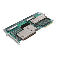
SMART Embedded Computing PCIE-7217 Installation And Use Manual (108 pages)
Brand:
SMART Embedded Computing
| Category:
PCI Card
| Size: 2 MB
Table of Contents
Table of Contents
3
About this Manual
11
Safety Notes
17
Notice de Sécurité
25
Sicherheitshinweise
33
1 Introduction
41
Overview
41
Figure 1-1 PCIE-7217 Card
41
Hardware Description
42
Features
42
Figure 1-2 Mechanical Layout
42
Software Overview
43
Certified Compliances
43
Table 1-1 Certified Compliances
43
Standard Compliances
44
Ordering and Support Information
44
Table 1-2 Standard Compliances
44
2 Hardware Preparation and Installation
45
Overview
45
Unpacking and Inspecting the PCIE-7217 Card
45
Environmental, Thermal, and Power
46
Environmental and Thermal Requirements
46
Table 2-1 Environmental and Thermal Requirements
46
Power Requirements
47
Precautions
47
Table 2-2 Power Requirements
47
ESD Prevention
48
PCIE-7217 Card Installation and Removal
49
PCIE-7217 Card Installation
49
PCIE-7217 Card Removal
51
3 Functional Description
53
Overview
53
CPU Complex
53
Figure 3-1 PCIE-7217 Block Diagram
53
Platform Controller Hub
54
Processor
54
DDR4 Memory
54
Storage
55
On-Board SSD
55
Socketed (M.2) SSD
55
Ethernet Controller
55
Usb
55
UART (COM Port)
55
Real Time Clock
56
Trusted Platform Module
57
Power
57
3.11 Temperature Sensors
57
Figure 3-2 Location of Temperature Sensors
57
Clock Distribution
58
Reset Management
58
4 Controls, Indicators, and Connectors
59
Overview
59
Connectors
59
PCIE-7217 Face Plate View
59
Figure 4-1 PCIE-7217 Face Plate
59
PCI Express Edge Connector
60
Table 4-1 PCI Express Edge Connector 1 Pinout
60
Maxcore™ Expansion Edge Connector
64
Table 4-2 Maxcore Expansion Edge Connector 2 Pinout
66
Console Access Port (USB Slave)
69
USB Host Ports
69
Table 4-3 Console Access Port (USB Slave) Pinout
69
Table 4-4 USB Host Ports Pinout
69
Leds
70
POST Code Leds
70
On-Board SSD Activity Leds
70
Figure 4-2 POST Leds
70
Figure 4-3 Location of On-Board SSD Activity LED for CPU1 (D13)
70
Figure 4-4 Location of On-Board SSD Activity LED for CPU2 (D6)
71
Table 4-5 On-Board SSD Activity Leds
71
SSD Activity Leds
72
Figure 4-5 Location of M.2 SSD Activity Leds (D7 and D8)
72
Table 4-6 M.2 SSD Activity Leds
72
Face Plate Leds
73
Figure 4-6 Face Plate Leds
73
Table 4-7 Face Plate Leds
73
Backplane Ethernet Communication Status/Activity Leds
74
Figure 4-7 Location of Backplane Ethernet Communication Status Leds
74
Table 4-8 Backplane Ethernet Communication Leds
74
Controls
75
Figure 4-8 Reset Buttons S3 and S4, and Switch S1 Location
75
Table 4-9 Switch S1 Settings
75
5 Bios
77
Overview
77
Accessing the BIOS Setup Screen
77
Figure 5-1 BIOS Setup Screen
78
Legend Bar
79
Menu Bar
79
Table 5-1 BIOS Setup Menu Bar
79
Field Help
80
Table 5-2 Legend Keys
80
General Help
81
Configuring BIOS Setup Settings
81
Main Menu
81
Figure 5-2 General Help Menu
81
Figure 5-3 Main Menu
82
Table 5-3 Main Menu
82
Advanced Menu
83
Figure 5-4 Advanced Menu
83
Table 5-4 Advanced Menu
83
Boot Configuration
84
Figure 5-5 Boot Configuration
84
Console Redirection Setup
85
Figure 5-6 Console Redirection Setup
85
Table 5-5 Console Redirection Setup
86
Security Menu
87
Figure 5-7 Security Menu
87
Power Menu
88
Figure 5-8 Power Menu
88
Table 5-6 Security Menu
88
Boot Menu
89
Figure 5-9 Boot Menu
89
Table 5-7 Boot Menu
89
Exit Menu
91
Figure 5-10 Exit Menu
91
Table 5-8 Exit Menu
91
BIOS Boot Parameter
92
Information for Other Software
93
6 Software
95
Overview
95
Management CPU Software
95
Installing Linux
95
Table 6-1 List of Files in Delivery Package
95
Disk Installation
96
Login
97
Firmware Upgrade
97
Table 6-2 Login Credentials
97
Query Command
98
Show Command
98
Upgrade Command
99
Upgrading the BIOS
99
Upgrading the CPLD
100
Other Operating Systems
100
Microsoft Windows
101
Drivers
101
Table 6-3 Available Drivers
101
Installation Procedures
102
Related Documentation
105
SMART Embedded Computing Documentation
105
Table A-1 SMART EC Documentation
105
Advertisement
Advertisement
Related Products
SMART Embedded Computing PrAMC-7311
SMART Embedded Computing Penguin Edge RTM-ATCA-F140
SMART Embedded Computing Categories
Single board computers
Control Unit
Motherboard
Computer Hardware
Storage
More SMART Embedded Computing Manuals
Login
Sign In
OR
Sign in with Facebook
Sign in with Google
Upload manual
Upload from disk
Upload from URL