Table of Contents
Advertisement
Advertisement
Table of Contents

Related Manuals for Cisco 4G-ANTM-OM-CM


Summary of Contents for Cisco 4G-ANTM-OM-CM
- Page 1 Cisco Industrial Routers and Industrial Wireless Access Points Antenna Guide May 2019 Cisco Systems, Inc. www.cisco.com Cisco has more than 200 offices worldwide. Addresses, phone numbers, and fax numbers are listed on the Cisco website at www.cisco.com/go/offices.
- Page 2 Cisco and the Cisco logo are trademarks or registered trademarks of Cisco and/or its affiliates in the U.S. and other countries. To view a list of Cisco trademarks, go to this URL: www.cisco.com/go/trademarks. Third-party trademarks mentioned are the property of their respective owners. The use of the word partner does not imply a partnership relationship between Cisco and any other company.
- Page 3 TIAL, OR INCIDENTAL DAMAGES, INCLUDING, WITHOUT LIMITATION, LOST PROFITS OR LOSS OR DAM- AGE TO DATA ARISING OUT OF THE USE OR INABILITY TO USE THIS MANUAL, EVEN IF CISCO OR ITS SUPPLIERS HAVE BEEN ADVISED OF THE POSSIBILITY OF SUCH DAMAGES.
-
Page 4: Table Of Contents
Cisco General Information ........ - Page 5 Cisco.com.........
- Page 6 Cisco Bug Search Tool ........
- Page 7 Obtaining Documentation and Submitting a Service Request ....... Cisco Aironet Four-Element, MIMO, Dual-Band Ceiling Mount Omni-Directional Antenna (AIR-ANT2524V4C-R) .
- Page 8 Obtaining Documentation and Submitting a Service Request ......Cisco Aironet 2.4 GHz and 5 GHz Dual-Band Polarization-Diverse Directional Array Antenna (AIR-ANT2566D4M-R).
- Page 9 Communications, Services, and Additional Information ........Cisco Aironet 2.4-GHz/5-GHz 8-dBi Directional Antenna (AIR-ANT2588P3M-N) .
- Page 10 Cisco Bug Search Tool ........
- Page 11 Obtaining Documentation and Submitting a Service Request ....... Cisco Dual Port, Dual Band Vehicle Mount and Fixed Infrastructure WLAN Antenna (ANT-2-WLAN-D-O).
- Page 12 Obtaining Documentation and Submitting a Service Request ......Cisco Multiband Panel Outdoor 3G Antenna (ANT-3G-PNL-OUT-N) .
- Page 13 Obtaining Documentation and Submitting a Service Request ....... Cisco Outdoor Omnidirectional Antenna for 2G/3G/4G Cellular (ANT-4G-OMNI-OUT-N) .
- Page 14 Obtaining Documentation and Submitting a Service Request ......Cisco Integrated 4G Low-profile Outdoor Saucer Antenna (ANT-4G-SR-OUT-TNC) .
- Page 15 Obtaining Documentation and Submitting a Service Request ....... Cisco 5-in-1 Vehicle Mount and Fixed Infrastructure Antenna (ANT-5-4G2WL2G1-O) .
- Page 16 Obtaining Documentation and Submitting a Service Request ......Cisco Outdoor 5 dBI Omni Antenna for 863-928 MHz WPAN, LoRaWan, and ISM (ANT-LPWA-DB-O-N-5) .
- Page 17 Obtaining Documentation and Submitting a Service Request ....... Cisco Vandal Resistant Omni-directional Dome Antenna for 860-928 MHz ISM, WPAN and LoRaWAN (ANT-UN-MP-OUT-QMA) .
- Page 18 Obtaining Documentation and Submitting a Service Request ......Cisco Outdoor Omni Antenna for 900 MHz WPAN (ANT-WPAN-OM-OUT-N).
- Page 19 Installing the Cisco Active GPS Antenna..........Installation Guidelines for the Cisco Active GPS Antenna ......
- Page 20 Connecting the Antenna to the Router ..........Obtaining Documentation and Submitting a Service Request .
-
Page 22: Cisco Industrial Routers And Industrial Wireless Access Points Antenna Guide
Cisco Industrial Routers and Industrial Wireless Access Points Antenna Guide This document provides the descriptions and installation instructions for wireless antennas supported on the Cisco Industrial Series Routers and Industrial Wireless Access Points. This guide is not intended to replace existing hardware installation guides, software configuration guides, or other sources of information that are product specific. -
Page 23: Installation Requirements
If you are installing an antenna for the first time, for your own safety as well as others, seek professional assistance. Your Cisco sales representative can explain which mounting method to use for the size and type antenna you are about to install. -
Page 24: Antenna Connections
Cisco Industrial Routers and Industrial Wireless Access Points Antenna Guide If the antenna is designed to create an omnidirectional broadcast pattern, the antenna should be mounted clear of any obstructions to the sides of the radiating element. Antenna installation and replacement should only be performed at one of the following, certified location types: ... -
Page 25: General Installation Instructions For Mounting Antennas
Cisco Industrial Routers and Industrial Wireless Access Points Antenna Guide — Signals penetrate three or four concrete and wood block walls without degrading signal strength. — Signals penetrate five or six walls constructed of drywall or wood without degrading signal strength. -
Page 26: Unused Antenna Ports
Cisco provides Cisco.com as a starting point for all technical assistance. Customers and partners can obtain documentation, troubleshooting tips, and sample configurations from online tools by using the Cisco Technical Assistance Center (TAC) Web Site. Cisco.com registered users have complete access to the technical support resources on the Cisco TAC Web Site. -
Page 27: Product Specific Guides For Industrial Routers
Cisco Industrial Routers and Industrial Wireless Access Points Antenna Guide Cisco IW3702 Access Point Getting Started Guide http://www.cisco.com/c/en/us/td/docs/wireless/outdoor_industrial/iw3702/hardware/install/guide/iw3702-gsg.html Product Specific Guides for Industrial Routers Cisco 807 Industrial Integrated Services Routers Cisco 809 Industrial Integrated Services Routers ... -
Page 28: Antenna Selection Table
Antenna Selection Table This section is designed to provide detailed information for each antenna that can be used for Cisco Industrial Routers and Industrial Wireless Access Points. This document also contains selection tables for the Cisco antennas and accessories, as well as basic compatibility information with Cisco Industrial Routers and Access Points Cisco antennas and accessories, as well as installation scenarios, and technical specifications and diagrams of the available antennas. -
Page 29: Cellular 2G/3G/4G Antennas
Part Number / Description RF Connectors Antenna Frequency Band Industrial Products Where Support and Gain Supported Cisco 5-in-1 Vehicle Mount and Fixed 2 x 4G LTE, TNC(m) 4G LTE 698-960, Good fit for IR829. Infrastructure Antenna 1448-1511, 1710-2400, 2 x 2.4/5 GHz WiFi, Can be used with other (ANT-5-4G2WL2G1-O). - Page 30 CGR1120 and GSM900/GSM1800/UMTS/LTE2600 CGR1240. bands. In most cases adapters or cables are required. Cisco Multiband Panel Outdoor 4G MIMO Dual type N female 698-960 MHz 8.0-10.0 dBi IR807, IR809, and IR829 Antenna (ANT-4G-PNL-OUT-N). direct connector 1710-2170 MHz 6.0-8.5...
- Page 31 LTE-ANTM-D antennas have high standalone efficiency, and maintain high efficiency when directly installed on front plate of a small or medium size Cisco router. However, depending on chassis size and a variety of other electromagnetic considerations, installing the antenna directly on the chassis is not always recommended.
-
Page 32: Gps/Gnss Antennas
1575.42 +/- 1 MHz, support of multiple technologies. GPS L1 Cisco Cellular and GPS 3-in-1 Vehicle Mount and Cellular – TNC 1 dBi zenith, plus IR807, IR809, and IR829 Fixed Infrastructure Antenna (ANT-3-4G2G1-O). - Page 33 Part Number / Description RF Connectors Antenna Frequency Industrial Products Where Band Support and Supported Gain Cisco GPS Antenna (ANT-GPS-OUT-TNC). Right-angle TNC Active GPS antenna, CGR1120 router use case male 4.0 dBi min at requires ANT-ADPTR-Q-TNC Active GPS antenna, integrated 15' LMR-100 Zenith, 1575.42...
- Page 34 IR1101 with P-LTE cellular 1575.42 MHz, plus Active GPS antenna that can be physically module 27dB amplifier gain connected to the Cisco Integrated Services C819HG-LTE and C819HG-4G Routers (ISRs) and Cisco Enhanced High-Speed WAN Interface Cards (EHWICs) to receive GPS broadcasts from satellites.
-
Page 35: Wpan, Ism, And Lorawan Antennas
Wi-Fi Antennas NOTE: Cisco has the broadest selection of WiFi antennas in the industry. Not all combinations of antennas and routers are supported or tested. For detailed information about antennas supported please check the documentation available for your router or access point. - Page 36 Dual Band 2.4 GHz + 5 GHz Antennas In addition to the information found in this guide, another detailed source for Cisco WiFi antennas, Access Points and deployment considerations can be found here: Cisco Aironet Antennas and Accessories Reference Guide...
-
Page 37: Single Band 2.4 Ghz Antennas
Part Number / Description RF Connectors Antenna Frequency Industrial Products Where Band Support and Supported Gain Cisco Aironet 2.4 GHz 13-dBi Directional Antenna Type N Male WiFi 2.4 Ghz IW3702 in FlexPort mode only (AIR-ANT2413P2M-N). 13 dBi IW3702 use case requires 2-Element Patch Array designed for outdoor use N-type cables. - Page 38 Part Number / Description RF Connectors Antenna Frequency Industrial Products Where Band Support and Supported Gain Cisco Aironet 5-GHz 13-dBi Directional Antenna Type N Male WiFi 5 GHz IW3702 in FlexPort mode only (AIR-ANT5114P2M-N). 13 dBi IW3702 use case requires 2-Port Directional antenna with N-type connectors N-type cables.
-
Page 39: Dual Band 2.4 Ghz + 5 Ghz Antennas
Part Number / Description RF Connectors Antenna Frequency Industrial Products Where Band Support and Supported Gain Cisco Dual Port, Dual Band Vehicle Mount and WiFi 2.4G/5G IR829 2 x 3 foot Fixed Infrastructure WLAN Antenna LMR-240 cables 4.0 dBi typical, 5.1 (ANT-2-WLAN-D-O). - Page 40 AIR-ANT2524DW-R). AIR-ACC370-NM-RF coaxial 4 dBi 5. GHz High-performance, dual-band dipole antenna adapters designed for use with Cisco Aironet 2.4 GHz and 5 Matching antenna color is the GHz radio products with dual-band white AIR-ANT2524DW-R reverse-polarity TNC (RP-TNC) antenna ports. IR829...
-
Page 41: Planned Eos Antennas
CGR 1000 2500-2700 MHz. The 4G-LTE-ANTM-D omnidirectional dipole Connected Grid Modules antenna is designed for indoor use with Cisco 4G 2 dBi and Cisco 3G wireless Integrated Services Routers Generation 2 (ISRs G2) and Enhanced High-Speed WAN Interface Cards (EHWICs). -
Page 42: Eos Antennas
3.5 dBi 1710-2170 non-integrated coaxial cable. No cable (option CGR1120 chassis class). 4 dBi 2300-2700 Cisco Outdoor Omni Antenna for 900 MHz WPAN Type N female WPAN 902-928 MHz IR509, IR510, and IR529 as (ANT-WPAN-OM-OUT-N). only well as WPAN... - Page 43 Antenna Selection Table...
-
Page 44: Cisco Rf Cables And Accessories
TNC(m) to TNC(f) RF cable TNC(m) to SMA(m) RF cables Cellular Antenna Extension Bases The following tables provide information for the Extension Bases supported by Cisco. Extension Bases Other Accessories The following table provides information for other accessories supported by Cisco. - Page 45 Cisco RF Cables and Accessories Table 1 N(m) to N(m) RF cables Antenna Cable Type Description RF Loss AIR-CAB002L240-N N(m)-STR to N(m)-RA 0.2dB @ 0.7 GHz LMR-240, 2 foot RF cable 0.3dB @ 1.0 GHz Type: Indoor Interconnect. 0.4dB @ 1.7 GHz Not DB, CMR or CMP 0.5dB @ 2.4 GHz...
- Page 46 Cisco RF Cables and Accessories Table 2 N(m) to QMA(m) RF cables Antenna Cable Type Description RF Loss CAB-L240-10-Q-N N(m)-STR to QMA(m)-RA 0.8dB @ 0.7 GHz LMR-240, 10 foot RF cable 0.9dB @ 1.0 GHz Type: FR/CMR (Communication Cable Riser) 1.2dB @ 1.7 GHz...
- Page 47 Cisco RF Cables and Accessories Antenna Cable Type Description RF Loss AIR-CAB050LL-R RPTNC (plug)-STR to RPTNC (jack)-STR 3.4dB @ 2.4 GHz LMR-400, 50 foot RF cable 5.75dB @ 5.8 GHz Type: outdoor DB (direct burial) AIR-CAB100ULL-R RPTNC (plug)-STR to RPTNC (jack)-STR 4.4dB @ 2.4 GHz...
- Page 48 Cisco RF Cables and Accessories Table 6 N(m) to TNC(m) RF cable Antenna Cable Type Description RF Loss CAB-L400-20-TNC-N TNC(m)-RA to N(m)-STR 0.8dB @ 0.7 GHz LMR-400, 20 foot RF cable 1.0dB @ 1.0 GHz Type: outdoor DB (direct burial) 1.3dB @ 1.7 GHz...
- Page 49 Cisco RF Cables and Accessories Table 8 TNC(m) to SMA(m) RF cables Antenna Cable Type Description RF Loss CAB-L240-10-SM-TM SMA(m)-STR to TNC(m)-STR 0.8dB @ 0.7 GHz LMR-240, 10ft RF cable 0.9dB @ 1.0 GHz Type: outdoor DB (direct burial) 1.2dB @ 1.7 GHz 1.5dB @ 2.4 GHz...
-
Page 50: Cellular Antenna Extension Bases
Cisco RF Cables and Accessories Cellular Antenna Extension Bases The following tables provide information for the Extension Bases supported by Cisco. Table 9 Extension Bases Extension Base PID Description RF Loss 4G-AE010-R TNC(m)-STR to TNC(f)-STR 1.1dB @ 0.7 GHz LMR-195, 10 foot RF cable 1.4dB @ 1.0 GHz... -
Page 51: Accessories
Cisco RF Cables and Accessories Accessories Table 10 Cisco Lightning Arrestors Cisco PID Connectors Type Arrestor Type and Frequency Range (MHz) CGR-LA-NM-NF N(m)-STR to N(f)-STR DC to 6000 MHz GDT type Supports active GNSS antennas, passes DC ACC-LA-H-NM-NF N(m)-STR to N(f)-STR... -
Page 52: Cisco 4G Indoor Ceiling-Mount Omnidirectional Antenna (4G-Antm-Om-Cm)
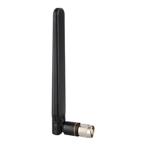
Obtaining Documentation Overview The 4G-ANTM-OM-CM antenna is a ceiling-mount omnidirectional antenna that operates in any of the 3G or 4G bands. These bands cover the following frequencies: 700, 800, 900, 1700, 1800, 1900, 2100,and 2600 MHz. This antenna is designed for use with Cisco 3G cellular Enhanced High-Speed WAN Interface Cards (EHWICs) and is compatible with Cisco 3G cellular products using a threaded Neill-Concelman (TNC) Male connector. - Page 53 Running H/F 1 Running H/F 2 Figure 1 shows a front view of the 4G-ANTM-OM-CM antenna. The green circle around the Cisco logo means that this is a 4G antenna. Figure 1 Cisco 4G-ANTM-OM-CM Antenna (Front View)
- Page 54 Running H/F 1 Running H/F 2 Figure 2 shows a side view of the 4G-ANTM-OM-CM antenna. Figure 2 Cisco 4G-ANTM-OM-CM Antenna (Side View) Mounting screws and anchors (#6 x 1-1/4”) Mounting nut for mounting on a hard ceiling Self-adhesive screw covers...
-
Page 55: Technical Specifications
Running H/F 1 Running H/F 2 Figure 3 shows a top view of the 4G-ANTM-OM-CM antenna. Figure 3 Cisco 4G-ANTM-OM-CM Antenna (Top View) Technical Specifications The following table lists the technical specifications for the 4G-ANTM-OM-CM antenna. - Page 56 Running H/F 1 Running H/F 2 Antenna type Low profile, ceiling-mount omnidirectional Operating frequency range 698–806 MHz 824–894 MHz 925 –960 MHz 1575 MHz 1710–1885 MHz 1920–1980 MHz 2110–2170 MHz 2500–2690 MHz Nominal Impedance 50 Ohms Voltage Standing Wave Ratio (VSWR) ...
- Page 57 Running H/F 1 Running H/F 2 Figure 4 shows the azimuth plane patterns for the 700 MHz band for the 4G-ANTM-OM-CM antenna. Figure 4 Azimuth Plane Patterns for the 700 MHz Band...
- Page 58 Running H/F 1 Running H/F 2 Figure 5 shows the azimuth plane patterns for the 800 MHz band for the 4G-ANTM-OM-CM antenna. Figure 5 Azimuth Plane Patterns for the 800 MHz Band...
- Page 59 Running H/F 1 Running H/F 2 Figure 6 shows the azimuth plane patterns for the 900 MHz band for the 4G-ANTM-OM-CM antenna. Figure 6 Azimuth Plane Patterns for the 900 MHz Band...
- Page 60 Running H/F 1 Running H/F 2 Figure 7 shows the azimuth plane patterns for the 1700 MHz band for the 4G-ANTM-OM-CM antenna. Figure 7 Azimuth Plane Patterns for the 1700 MHz Band...
- Page 61 Running H/F 1 Running H/F 2 Figure 8 shows the azimuth plane patterns for the 1800 MHz band for the 4G-ANTM-OM-CM antenna. Figure 8 Azimuth Plane Patterns for the 1800 MHz Band...
- Page 62 Running H/F 1 Running H/F 2 Figure 9 shows the azimuth plane patterns for the 1900 MHz band for the 4G-ANTM-OM-CM antenna. Figure 9 Azimuth Plane Patterns for the 1900 MHz Band...
- Page 63 Running H/F 1 Running H/F 2 Figure 10 shows the azimuth plane patterns for the 2100 MHz band for the 4G-ANTM-OM-CM antenna. Figure 10 Azimuth Plane Patterns for the 2100 MHz Band...
- Page 64 Running H/F 1 Running H/F 2 Figure 11 shows the azimuth plane patterns for the 2600 MHz band for the 4G-ANTM-OM-CM antenna. Figure 11 Azimuth Plane Patterns for the 2600 MHz Band...
- Page 65 Running H/F 1 Running H/F 2 Figure 12 shows the elevation plane patterns (Phi = 0 degree plane cut) for the 700 MHz band for the 4G-ANTM-OM-CM antenna. Figure 12 Elevation Plane Patterns (Phi = 0 degree Plane Cut) for the 700 MHz Band...
- Page 66 Running H/F 1 Running H/F 2 Figure 13 shows the elevation plane patterns (Phi = 0 degree plane cut) for the 800 MHz band for the 4G-ANTM-OM-CM antenna. Figure 13 Elevation Plane Patterns (Phi = 0 degree Plane Cut) for the 800 MHz Band...
- Page 67 Running H/F 1 Running H/F 2 Figure 14 shows the elevation plane patterns (Phi = 0 degree plane cut) for the 900 MHz band for the 4G-ANTM-OM-CM antenna. Figure 14 Elevation Plane Patterns (Phi = 0 degree Plane Cut) for the 900 MHz Band...
- Page 68 Running H/F 1 Running H/F 2 Figure 15 shows the elevation plane patterns (Phi = 0 degree plane cut) for the 1700 MHz band for the 4G-ANTM-OM-CM antenna. Figure 15 Elevation Plane Patterns (Phi = 0 degree Plane Cut) for the 1700 MHz Band...
- Page 69 Running H/F 1 Running H/F 2 Figure 16 shows the elevation plane patterns (Phi = 0 degree plane cut) for the 1800 MHz band for the 4G-ANTM-OM-CM antenna. Figure 16 Elevation Plane Patterns (Phi = 0 degree Plane Cut) for the 1800 MHz Band...
- Page 70 Running H/F 1 Running H/F 2 Figure 17 shows the elevation plane patterns (Phi = 0 degree plane cut) for the 1900 MHz band for the 4G-ANTM-OM-CM antenna. Figure 17 Elevation Plane Patterns (Phi = 0 degree Plane Cut) for the 1900 MHz Band...
- Page 71 Running H/F 1 Running H/F 2 Figure 18 shows the elevation plane patterns (Phi = 0 degree plane cut) for the 2100 MHz band for the 4G-ANTM-OM-CM antenna. Figure 18 Elevation Plane Patterns (Phi = 0 degree Plane Cut) for the 2100 MHz Band...
- Page 72 Running H/F 1 Running H/F 2 Figure 19 shows the elevation plane patterns (Phi = 0 degree plane cut) for the 2600 MHz band for the 4G-ANTM-OM-CM antenna. Figure 19 Elevation Plane Patterns (Phi = 0 degree Plane Cut) for the 2600 MHz Band...
- Page 73 Running H/F 1 Running H/F 2 Figure 20 shows the elevation plane patterns (Phi = 90 degree plane cut) for the 700 MHz band for the 4G-ANTM-OM-CM antenna. Figure 20 Elevation Plane Patterns (Phi = 90 degree Plane Cut) for the 700 MHz Band...
- Page 74 Running H/F 1 Running H/F 2 Figure 21 shows the elevation plane patterns (Phi = 90 degree plane cut) for the 800 MHz band for the 4G-ANTM-OM-CM antenna. Figure 21 Elevation Plane Patterns (Phi = 90 degree Plane Cut) for the 800 MHz Band...
- Page 75 Running H/F 1 Running H/F 2 Figure 22 shows the elevation plane patterns (Phi = 90 degree plane cut) for the 900 MHz band for the 4G-ANTM-OM-CM antenna. Figure 22 Elevation Plane Patterns (Phi = 90 degree Plane Cut) for the 900 MHz Band...
- Page 76 Running H/F 1 Running H/F 2 Figure 23 shows the elevation plane patterns (Phi = 90 degree plane cut) for the 1700 MHz band for the 4G-ANTM-OM-CM antenna. Figure 23 Elevation Plane Patterns (Phi = 90 degree Plane Cut) for the 1700 MHz Band...
- Page 77 Running H/F 1 Running H/F 2 Figure 24 shows the elevation plane patterns (Phi = 90 degree plane cut) for the 1800 MHz band for the 4G-ANTM-OM-CM antenna. Figure 24 Elevation Plane Patterns (Phi = 90 degree Plane Cut) for the 1800 MHz Band...
- Page 78 Running H/F 1 Running H/F 2 Figure 25 shows the elevation plane patterns (Phi = 90 degree plane cut) for the 1900 MHz band for the 4G-ANTM-OM-CM antenna. Figure 25 Elevation Plane Patterns (Phi = 90 degree Plane Cut) for the 1900 MHz Band...
- Page 79 Running H/F 1 Running H/F 2 Figure 26 shows the elevation plane patterns (Phi = 90 degree plane cut) for the 2100 MHz band for the 4G-ANTM-OM-CM antenna. Figure 26 Elevation Plane Patterns (Phi = 90 degree Plane Cut) for the 2100 MHz Band...
-
Page 80: System Requirements
Running H/F 1 Running H/F 2 Figure 27 shows the elevation plane patterns (Phi = 90 degree plane cut) for the 2600 MHz band for the 4G-ANTM-OM-CM antenna. Figure 27 Elevation Plane Patterns (Phi = 90 degree Plane Cut) for the 2600 MHz Band System Requirements The 4G-ANTM-OM-CM antenna requires a Cisco 3G EHWIC that uses a TNC-Male connector. -
Page 81: Safety Instructions
Running H/F 1 Running H/F 2 The density of the materials used in a building’s construction determines the number of walls the signal must pass through and still maintain adequate coverage. Consider the following before choosing the location to install your antenna: —... -
Page 82: Installation Instructions
Cable Distribution System ONLY through a device that is approved for direct connection. Statement 1078 Installation Instructions To install the Cisco 4G-ANTM-OM-CM antenna on a ceiling: Drill a 3/4” diameter hole in the ceiling where you want to mount the antenna. - Page 83 To extend the coaxial cable included with your antenna, we recommend an ultra-low-loss coaxial cable for installation flexibility without a significant loss in range. The following table lists insertion loss information about ULL extension coaxial cables available from Cisco. Cisco Product Number...
-
Page 84: Obtaining Documentation
Installation Instructions for the Cisco 4G-ANTM-OM-CM Antenna Router Obtaining Documentation Cisco documentation and additional literature are available on Cisco.com. Cisco also provides several ways to obtain technical assistance and other technical resources. These sections explain how to obtain technical information from Cisco Systems. -
Page 85: Cisco.com
Cisco and the Cisco logo are trademarks or registered trademarks of Cisco and/or its affiliates in the U.S. and other countries. To view a list of Cisco trademarks, go to this URL: www.cisco.com/go/trademarks. Third-party trademarks mentioned are the property of their respective owners. The use of the word partner does not imply a partnership relationship between Cisco and any other company. -
Page 86: Cisco 4G/3G Omnidirectional Dipole Antenna (4G-Lte-Antm-D)
Safety Instructions, page 95 Overview The 4G-LTE-ANTM-D omnidirectional dipole antenna is designed for indoor use with Cisco 4G and Cisco 3G wireless Integrated Services Routers Generation 2 (ISRs G2) and Enhanced High-Speed WAN Interface Cards (EHWICs). The 4G-LTE-ANTM-D antenna is marked with a green band and the product ID (PID) to indicate that it supports 4G Long Term Evolution (LTE) networks. - Page 87 Cisco 4G/3G Omnidirectional Dipole Antenna (4G-LTE-ANTM-D) Figure 1 Cisco 4G-LTE-ANTM-D Ominidirectional Dipole Antenna, TNC Connector, and Articulation Joint 4G-LTE-ANTM-D 0 degree position TNC connector 45 degree position Green band 90 degree position Product ID Articulating joint...
-
Page 88: Specifications
Antennas were designed and tested to high RF efficiency in all supported cellular bands. Detailed technical specifications can be obtained through your Cisco authorized partner or Cisco account representative. Maximum Peak Gain 2 dBi Figure 2 Elevation Cut (AMPS) Phi 0 Degree Plane for Cisco 4G-LTE-ANTM-D... - Page 89 Cisco 4G/3G Omnidirectional Dipole Antenna (4G-LTE-ANTM-D)
- Page 90 Cisco 4G/3G Omnidirectional Dipole Antenna (4G-LTE-ANTM-D) Figure 3 Elevation Cut (AMPS) Phi 90 Degree Plane for Cisco 4G-LTE-ANTM-D...
- Page 91 Cisco 4G/3G Omnidirectional Dipole Antenna (4G-LTE-ANTM-D) Figure 4 Azimuth Cut (AMPS) for Cisco 4G-LTE-ANTM-D...
- Page 92 Cisco 4G/3G Omnidirectional Dipole Antenna (4G-LTE-ANTM-D) Figure 5 Elevation Cut (PCS) Phi 0 Degree Plane for Cisco 4G-LTE-ANTM-D...
- Page 93 Cisco 4G/3G Omnidirectional Dipole Antenna (4G-LTE-ANTM-D) Figure 6 Elevation Cut (PCS) Phi 90 Degree Plane for Cisco 4G-LTE-ANTM-D...
-
Page 94: System Requirements
Installation Notes This antenna is designed to be mounted directly to any Cisco 4G and Cisco 3G wireless ISR and EHWIC with a TNC connector by simply threading it onto the mating connector. Mount and deploy the antenna at the 0-degree position, 45-degree position, or the 90-degree position, and then change that position at will. -
Page 95: Safety Instructions
Cisco 4G/3G Omnidirectional Dipole Antenna (4G-LTE-ANTM-D) Follow these guidelines to ensure the best possible performance: When used on an EHWIC, always mount the antenna on an appropriate extension cable and antenna stand. The antenna performance will not be optimal if mounted directly to an EHWIC. Mounting directly to a fixed router (without an EHWIC) is allowed. - Page 96 Cisco 4G/3G Omnidirectional Dipole Antenna (4G-LTE-ANTM-D) Caution: Remember that electric power cables and telephone lines look alike. For your safety, assume that any line is an electric power line until determined otherwise. Call your local power company or building maintenance organization if you are unsure about cables close to your mounting location.
- Page 97 Cisco 4G/3G Omnidirectional Dipole Antenna (4G-LTE-ANTM-D)
-
Page 98: Cisco Dual Lte-Single Gps Multi-Band Antenna Installation Guide (4G-Lte-Antm-O-3-B)
Cisco Dual LTE-Single GPS Multi-band Antenna Installation Guide (4G-LTE-ANTM-O-3-B) This document provides the description, supported features, and installation instructions of the Cisco Dual LTE-Single GPS Multi-band (4G-LTE-ANTM-O-3-B) Antenna. Caution: Read the information in Safety Precautions before installing or replacing antennas. -
Page 99: Parts List
Cisco Dual LTE-Single GPS Multi-band Antenna Installation Guide (4G-LTE-ANTM-O-3-B) Figure 1 4G-LTE-ANTM-O-3 Antenna Parts List The shipment of your antenna includes the following items: One Antenna Unit Two SMA-Female to TNC-Male Adapters Installation Guide Features of the 4G-LTE-ANTM-O-3-B Antenna The 4G-LTE-ANTM-O-3-B antenna supports the following features: ... - Page 100 Cisco Dual LTE-Single GPS Multi-band Antenna Installation Guide (4G-LTE-ANTM-O-3-B) Table 1 Specifications of RF antenna Operating Frequencies 698-960 MHz 1710-2700 MHz Polarization Vertical, linear Nominal Impedance 50 Ohms Gain (Typical) 2.5 dBi Maximum Power 3 Watts VSWR < 2.5:1 Elevation Plane (3 dB Beamwidth) 30°...
- Page 101 Cisco Dual LTE-Single GPS Multi-band Antenna Installation Guide (4G-LTE-ANTM-O-3-B) Table 2 Specifications of the GPS Antenna Frequency Band 1575.42 MHz (GPS L1) Amplifier Gain 26 dBc ± 3 dB Nominal Impedance 50 Ohms Output VSWR 1.5:1 typical DC Current 20 mA nominal; < 30 mA @ -40°C to +85° C DC Voltage 3.3-5 V...
- Page 102 Cisco Dual LTE-Single GPS Multi-band Antenna Installation Guide (4G-LTE-ANTM-O-3-B) Figure 3 The Antenna with Cable Labels MPN LABEL LTE-ID LABEL 2EA GPS ID LABEL Figure 4 shows the Low Band 698-960 MHz EL (PHI=0).
- Page 103 Cisco Dual LTE-Single GPS Multi-band Antenna Installation Guide (4G-LTE-ANTM-O-3-B) Figure 4 Low band 698-960 MHz EL (PHI=0) Figure 5 shows the Low Band 698-960 MHz EL (PHI=90).
- Page 104 Cisco Dual LTE-Single GPS Multi-band Antenna Installation Guide (4G-LTE-ANTM-O-3-B) Figure 5 Low band 698-960 MHz EL (PHI=90) Figure 6 shows the Low Band 698-960 MHz AZ (THETA=90).
- Page 105 Cisco Dual LTE-Single GPS Multi-band Antenna Installation Guide (4G-LTE-ANTM-O-3-B) Figure 6 Low Band 698-960 MHz AZ (THETA=90) Figure 7 shows High Band 1710-2700 MHz EL (PHI=0).
- Page 106 Cisco Dual LTE-Single GPS Multi-band Antenna Installation Guide (4G-LTE-ANTM-O-3-B) Figure 7 High Band 1710-2700 MHz EL (PHI=0) Figure 8 shows High Band 1710-2700 MHz EL (PHI=90).
- Page 107 Cisco Dual LTE-Single GPS Multi-band Antenna Installation Guide (4G-LTE-ANTM-O-3-B) Figure 8 High Band 1710-2700 MHz EL (PHI=90) Figure 9 shows High Band 1710-2700 MHz AZ (THETA=90).
-
Page 108: Supported Antennas
Cisco Dual LTE-Single GPS Multi-band Antenna Installation Guide (4G-LTE-ANTM-O-3-B) Figure 9 High Band 1710-2700 MHz AZ (THETA=90) Supported Antennas Table 3 lists the supported antennas. Table 3 Supported Antennas Part Number Description 4G-LTE-ANTM-O-3-W Indoor or outdoor low-profile antenna with 4-foot dongle, white radome. -
Page 109: Supported Antenna Accessories
Cisco Dual LTE-Single GPS Multi-band Antenna Installation Guide (4G-LTE-ANTM-O-3-B) Supported Antenna Accessories Table 4 lists the supported antenna accessories. Table 4 Supported Antenna Accessories Part Number Cable Length Maximum Insertion Loss 4G-CAB-LMR240-25 25 foot (7.5 m) 2.1 dB @ 700 MHz 4.0 dB @ 2.6 GHz... -
Page 110: Statement 1052—Installing And Grounding The Antenna
If you are installing an antenna for the first time, for your own safety as well as others, seek professional assistance. Your Cisco sales representative can explain which mounting method to use for the size and type of antenna you are about to install. -
Page 111: Installation Instructions
Cisco Dual LTE-Single GPS Multi-band Antenna Installation Guide (4G-LTE-ANTM-O-3-B) Installation Instructions The following section contains steps for installing the 4G-LTE-ANTM-O-3-B antenna: While choosing the location, keep the following in mind: — Attempt to center the antenna on a flat plane. -
Page 112: Deployment Scenarios
Cisco Dual LTE-Single GPS Multi-band Antenna Installation Guide (4G-LTE-ANTM-O-3-B) Figure 11 Bottom View of the Antenna 4G-LTE-ANTM-O-3-B 4G LTE 3 in 1 outdoor Black antenna 700MHZ www.cisco.com/go/4g SN: 14300881 INSTALLATION TORQUE 4.5Nm MPN: 07-01329-01 RoHs Complaint Made in: CN Product ID and Serialization Label... - Page 113 Cisco Dual LTE-Single GPS Multi-band Antenna Installation Guide (4G-LTE-ANTM-O-3-B) Figure 13 Deployment of an Antenna with One Router Router MODEM MAIN Power AC or DC input Adapter option available Figure 14 shows the deployment of 4G-LTE-ANTM-O-3-B on an ATM with dual routers.
-
Page 114: Related Documentation
Obtaining Documentation and Submitting a Service Request For information on obtaining documentation, submitting a service request, and gathering additional information, see the monthly What’s New in Cisco Product Documentation, which also lists all new and revised Cisco technical documentation, at: http://www.cisco.com/en/US/docs/general/whatsnew/whatsnew.html... - Page 115 Cisco Dual LTE-Single GPS Multi-band Antenna Installation Guide (4G-LTE-ANTM-O-3-B) Subscribe to the What’s New in Cisco Product Documentation as a Really Simple Syndication (RSS) feed and set content to be delivered directly to your desktop using a reader application. The RSS feeds are a free service and Cisco currently supports RSS version 2.0.
-
Page 116: Cisco Aironet 2.4 Ghz 13-Dbi Directional Antenna (Air-Ant2413P2M-N)
Cisco Aironet 2.4 GHz 13-dBi Directional Antenna (AIR-ANT2413P2M-N) This document outlines the specifications for the Cisco Aironet AIR-ANT2413P2M-N 2.4 GHz 13-dBi 2-Port Directional antenna with N-type connectors and provides instructions for mounting it. The antenna operates in the 2.4 GHz frequency band and is designed for use in outdoor environments. -
Page 117: Technical Specifications
(–40°C to 55°C) Elevation and Azimuth Plane Patterns System Requirements This antenna is designed for use with Cisco Aironet access points and bridges but can be used with any 2.4-GHz Cisco Aironet radio device that uses an N-male connector. -
Page 118: Safety Precautions
If you are installing an antenna for the first time, for your own safety as well as others, seek professional assistance. Your Cisco sales representative can explain which mounting method to use for the size and type antenna you are about to install. -
Page 119: Installation Guidelines
Cisco Aironet 2.4 GHz 13-dBi Directional Antenna (AIR-ANT2413P2M-N) Installation Guidelines Because the antennas transmit and receive radio signals, they are susceptible to RF obstructions and common sources of interference that can reduce throughput and range of the device to which they are connected. Follow these guidelines to ensure the best possible performance: ... -
Page 120: Mounting On A Pole
Cisco Aironet 2.4 GHz 13-dBi Directional Antenna (AIR-ANT2413P2M-N) Four 1/4-in. 20x3/4 carriage bolts Six 1/4-in. 20 hex nuts Six 1/4-in. 20 spring lock washers Six 1/4-in. 20 flat washers Two pipe clamps To attach the mount to the antenna and secure it to the pole, you need the following tools and equipment, which are not provided. - Page 121 Cisco Aironet 2.4 GHz 13-dBi Directional Antenna (AIR-ANT2413P2M-N) Figure 1 Attaching Antenna Mount Bracket Antenna mount bracket 1/4-in. spring lock washer 1/4-in. flat washer 1/4-in. 20 hex nut Attach elevation adjustable bracket as shown and loosely secure hardware. The carriage bolt square holes must be on the...
- Page 122 Cisco Aironet 2.4 GHz 13-dBi Directional Antenna (AIR-ANT2413P2M-N) Figure 2 Attaching Elevation Adjustable Bracket Elevation adjustable bracket 1/4-in. spring lock washer 1/4-in. 20x3/4 carriage bolt 1/4-in. 20 hex nut 1/4-in. flat washer Attach azimuth adjustable bracket to pipe routing band clamps as shown. Tighten the pipe clamps to a torque of 43-51...
- Page 123 Cisco Aironet 2.4 GHz 13-dBi Directional Antenna (AIR-ANT2413P2M-N) Figure 3 Attaching Azimuth Adjustable Bracket Azimuth adjustable bracket Pipe clamps Attach antenna assembly to azimuth bracket on pipe.
- Page 124 Cisco Aironet 2.4 GHz 13-dBi Directional Antenna (AIR-ANT2413P2M-N) Figure 4 Attaching Antenna Assembly 1/4-in. flat washer Elevation adjustable bracket 1/4-in. spring lock washer 1/4-in. 20x3/4 carriage bolt 1/4-in. 20 hex nut Adjust the position of the antenna to the desired azimuth and elevation angles and tighten all pivot hardware (4 places) to a maximum torque of 55 in-lbf (6.2 Nm).
-
Page 125: Installing The Optional Mounting Bracket Kit
For more information on mounting the antenna with the optional mounting bracket, refer to Installing Antenna Brackets on Cisco 1550 Series Outdoor Mesh Access Points. - Page 126 Cisco Aironet 2.4 GHz 13-dBi Directional Antenna (AIR-ANT2413P2M-N) Figure 6 Wall Mounting Figure 7 shows, in inches, the distance between the bracket mounting holes. Figure 7 Distance Between Bracket Mounting Holes 2.40 2.40 Attach antenna assembly to azimuth bracket, as shown in...
-
Page 127: Antenna Cable Information
Antenna Cable Information If the antenna is used with the Cisco 1552CU or 1552EU access point, the port A of the antenna must be connected to port 4 of the access point, port B of the antenna must be connected to port 6 of the access point, and port 5 of the access point must be capped with the cap enclosed with the antenna. - Page 128 Cisco Aironet 2.4 GHz 13-dBi Directional Antenna (AIR-ANT2413P2M-N) Cisco and the Cisco Logo are trademarks of Cisco Systems, Inc. and/or its affiliates in the U.S. and other countries. A listing of Cisco's trademarks can be found at www.cisco.com/go/trademarks. Third party trademarks mentioned are the property of their respective owners. The use of the word partner does not imply a partnership relationship...
- Page 129 Cisco Aironet 2.4 GHz 13-dBi Directional Antenna (AIR-ANT2413P2M-N)
-
Page 130: Cisco Aironet Omnidirectional Antennas Air-Ant2450V-N, Air-Ant2450Vg-N Air-Ant2450V-N-Hz, And Air-Ant2450Hg-N
This document describes the Cisco Aironet AIR-ANT2450V-N, AIR-ANT2450VG-N, AIR-ANT2450V-N-HZ, and AIR-ANT2450HG-N omnidirectional antennas and provides instructions for mounting. The antennas are designed for outdoor use with Cisco Aironet Outdoor Access Points (hereafter referred to as access points) with radios operating in the 2.4 GHz frequency band. -
Page 131: Technical Specifications
Cisco Aironet Omnidirectional Antennas AIR-ANT2450V-N, AIR-ANT2450VG-N, AIR-ANT2450V-N-HZ, and Technical Specifications Antenna Type Omnidirectional Operating Frequency Range 2400-2500 MHz VSWR 50 Ω Nominal Input Impedance Gain 5 dBi Polarization AIR-ANT2450VG-N: Vertical AIR-ANT2450HG-N: Horizontal Azimuth Plane Ripple 2 dB (Max) Elevation Plane 3 dB Beamwidth 30°... -
Page 132: Air-Ant2450V-N, Air-Ant2450Vg-N, And Air-Ant2450V-N-Hz
Cisco Aironet Omnidirectional Antennas AIR-ANT2450V-N, AIR-ANT2450VG-N, AIR-ANT2450V-N-HZ, and AIR-ANT2450V-N, AIR-ANT2450VG-N, and AIR-ANT2450V-N-HZ Figure 1 Azimuth Radiation Pattern Figure 2 Elevation Radiation Pattern... -
Page 133: Air-Ant2450Hg-N
(e.g. U.S.: NFPA 70, National Electrical Code, Article 810, Canada: Canadian Electrical Code, Section 54). Statement 280 For your safety, read and follow these safety precautions. Before you install an antenna, contact your Cisco account representative to explain which mounting method to use for the size and type of antenna that you are about to install. -
Page 134: Installation Notes
Obtaining Documentation and Submitting a Service Request For information on obtaining documentation, submitting a service request, and gathering additional information, see the monthly What’s New in Cisco Product Documentation, which also lists all new and revised Cisco technical documentation, at: http://www.cisco.com/c/en/us/td/docs/general/whatsnew/whatsnew.html. - Page 135 RSS Version 2.0. Cisco and the Cisco Logo are trademarks of Cisco Systems, Inc. and/or its affiliates in the U.S. and other countries. A listing of Cisco's trademarks can be found at www.cisco.com/go/trademarks. Third party trademarks mentioned are the property of their respective owners.
-
Page 136: Cisco Aironet 6.5-Dbi Diversity Patch Antenna (Air-Ant2465P-R)
Cisco Aironet 6.5-dBi Diversity Patch Antenna (AIR-ANT2465P-R) This describes the AIR-ANT2465P-R 6-dBi patch antenna specifications and mounting instructions. The antenna operates in the 2.4-GHz frequency range and is designed for use in both indoor and outdoor environments. These topics are discussed. -
Page 137: Technical Specifications
Left Antenna Azimuth and Elevation Pattern Right Antenna Azimuth and Elevation Pattern System Requirements This antenna is designed for use with Cisco Aironet access points and bridges but can be used with any 2.4-GHz Cisco Aironet radio device that utilizes an RP-TNC connector. -
Page 138: Safety Precautions
If you are installing an antenna for the first time, for your own safety as well as others, seek professional assistance. Your Cisco sales representative can explain which mounting method to use for the size and type antenna you are about to install. -
Page 139: Installation Guidelines
Cisco Aironet 6.5-dBi Diversity Patch Antenna (AIR-ANT2465P-R) Installation Guidelines If any part of the antenna system should come in contact with a power line, do not touch it or try to remove it yourself. Call your local power company. They will remove it safely. -
Page 140: Installing The Antenna
Cisco Aironet 6.5-dBi Diversity Patch Antenna (AIR-ANT2465P-R) Installing the Antenna Installing the Antenna You can install the antenna on any flat indoor or outdoor vertical surface. Hardware for mounting the antenna on drywall is provided. If you intend to install your antenna on another surface, you must provide the appropriate hardware. -
Page 141: Outdoor Installations
After the cable is attached to the antenna, ensure that the connections are sealed (if outdoors) to prevent moisture and other weathering elements from affecting performance. Cisco recommends using a coax seal (such as CoaxSeal) for outdoor connections. Silicon sealant or electrical tape are not recommended for sealing outdoor connections. -
Page 142: Cisco Bug Search Tool
Consult the dealer or an experienced radio/TV technician for help. Modifications to this product not authorized by Cisco could void the FCC approval and negate your authority to operate the product. The Cisco implementation of TCP header compression is an adaptation of a program developed by the University of California, Berkeley (UCB) as part of UCB’s public domain version of the UNIX operating system. - Page 143 IN NO EVENT SHALL CISCO OR ITS SUPPLIERS BE LIABLE FOR ANY INDIRECT, SPECIAL, CONSEQUENTIAL, OR INCIDENTAL DAMAGES, INCLUDING, WITHOUT LIMITATION, LOST PROFITS OR LOSS OR DAMAGE TO DATA ARISING OUT OF THE USE OR INABILITY TO USE THIS MANUAL, EVEN IF CISCO OR ITS SUPPLIERS HAVE BEEN ADVISED OF THE POSSIBILITY OF SUCH DAMAGES.
-
Page 144: Cisco Aironet 8-Dbi Omni-Directional Antenna (Air-Ant2480V-N)
This describes the Cisco Aironet AIR-ANT2480V-N 8 dBi Omni-directional Antenna, and provides specifications and mounting instructions. The antenna operates in the 2400 MHz frequency range and is designed for outdoor use with Cisco Aironet 1500 Series Lightweight Outdoor Mesh Access Points. -
Page 145: Technical Specifications
Cisco Aironet 8-dBi Omni-Directional Antenna (AIR-ANT2480V-N) Technical Specifications Table 1 Specifications Antenna type Omni-directional (collinear array) Operating frequency range 2400–2484 MHz VSWR < 1.7:1 Gain 8 dBi Polarization Linear, vertical Horizontal half-power 10 degrees beamwidth Vertical half-power Omni-directional beamwidth Length 19-1/2 in. - Page 146 Cisco Aironet 8-dBi Omni-Directional Antenna (AIR-ANT2480V-N) The attenuation can be in the form of an attenuator, coax cable loss, or both. This attenuation is required for the system to meet the regulatory requirements of the indicated country. Failure to install the minimum amount of attenuation shown results in non-compliant operation.
-
Page 147: System Requirements
Cisco Aironet 8-dBi Omni-Directional Antenna (AIR-ANT2480V-N) System Requirements This antenna is designed for use with Cisco Aironet access points and bridges but can be used with any Cisco Aironet radio device that uses an N-connector. Safety Precautions Warning: Installation of this antenna near power lines is dangerous. For your safety, follow the installation directions. -
Page 148: Choosing A Mounting Location
Cisco Aironet 8-dBi Omni-Directional Antenna (AIR-ANT2480V-N) Figure 1 Antenna Drain Hole Locations Antenna drain hole under the cap Antenna drain holes at the base Choosing a Mounting Location The antenna is designed to create an omni-directional broadcast pattern. To achieve this pattern, the access point should be mounted clear of any obstructions to the sides of the radiating element. -
Page 149: Communications, Services, And Additional Information
5-GHz antenna Access point 5-GHz antenna connector Communications, Services, and Additional Information To receive timely, relevant information from Cisco, sign up at Cisco Profile Manager. To get the business impact you’re looking for with the technologies that matter, visit Cisco Services. - Page 150 Consult the dealer or an experienced radio/TV technician for help. Modifications to this product not authorized by Cisco could void the FCC approval and negate your authority to operate the product. The Cisco implementation of TCP header compression is an adaptation of a program developed by the University of California, Berkeley (UCB) as part of UCB’s public domain version of the UNIX operating system.
- Page 151 Cisco Aironet 8-dBi Omni-Directional Antenna (AIR-ANT2480V-N)
-
Page 152: Cisco Aironet Four-Port Dual-Band Polarization-Diverse Antenna (Air-Ant2513P4M-N)
Krylon or Rust-Oleum. The antenna is designed for use in indoor and outdoor environments with Cisco Aironet 3702P and 1570 series access points. The following information is provided in this document: ... -
Page 153: Technical Specifications
Cisco Aironet Four-Port Dual-Band Polarization-Diverse Antenna (AIR-ANT2513P4M-N) Technical Specifications Antenna Type Dual-Band Polarization Diverse Patch Array Operating Frequency Ranges 2.4-2.5 GHz 5.15-5.925 GHz Nominal Input Impedance 50 Ohms 50 Ohms VSWR 1.6:1 1.5:1 (above 5.7 GHz to 5.9 GHz) 2:1 (from 5.15 GHz to 5.7 GHz) -
Page 154: Ghz Antenna Radiation Patterns
Cisco Aironet Four-Port Dual-Band Polarization-Diverse Antenna (AIR-ANT2513P4M-N) 2.4 GHz Ports A&C Azimuth Plane 2.4 GHz Ports A&C Elevation Plane 2.4 GHz Ports B&D Azimuth Plane 2.4 GHz Ports B&D Elevation Plane 5 GHz Antenna Radiation Patterns... -
Page 155: Antenna And Bracket Dimensions
Cisco Aironet Four-Port Dual-Band Polarization-Diverse Antenna (AIR-ANT2513P4M-N) 5 GHz Ports A&C Azimuth Plane 5 GHz Ports A&C Elevation Plane 5 GHz Ports B&D Azimuth Plane 5 GHz Ports B&D Elevation Plane Antenna and Bracket Dimensions Figure 2 Figure 3 show the overall dimensions of the antenna and bracket. - Page 156 Cisco Aironet Four-Port Dual-Band Polarization-Diverse Antenna (AIR-ANT2513P4M-N) Figure 2 Antenna and Bracket Dimensions (in millimeters) Figure 3 Rear View of Antenna (dimensions in millimeters)
-
Page 157: System Requirements
Cisco Aironet Four-Port Dual-Band Polarization-Diverse Antenna (AIR-ANT2513P4M-N) System Requirements This antenna is designed for use with Cisco Aironet 3702P and 1570 series access points. The antenna can be mounted on a wall, a ceiling, or a pole with a maximum diameter of 5 inches (12.7 cm). -
Page 158: Installation Notes
Cisco Aironet Four-Port Dual-Band Polarization-Diverse Antenna (AIR-ANT2513P4M-N) Call your local power company or building maintenance organization if you are unsure about cables close to your mounting location. When installing your antenna, do not use a metal ladder. Do dress properly: shoes with rubber soles and heels, rubber gloves, and a long sleeved shirt or jacket. -
Page 159: Tools And Equipment Required
Cisco Aironet Four-Port Dual-Band Polarization-Diverse Antenna (AIR-ANT2513P4M-N) Figure 4 Antenna Bracket Kit Contents Mounting flange Flat washers Mounting arm Lock washers Arm attachment bolts (5/16-18 x 1-5/8") Arm attachment nuts (5/16-18) Serrated washers Hose clamps (50 – 135 mm adjustment) NOTE: One flange (not pictured here) ships attached to the antenna. -
Page 160: Mounting On A Wall Or Ceiling
Cisco Aironet Four-Port Dual-Band Polarization-Diverse Antenna (AIR-ANT2513P4M-N) Slotted screwdriver to tighten the screws on the hose clamps A 5/16 in. (8mm) socket or box wrench NOTE: The pole or mast must be rigid enough to hold the weight of the antenna plus the associated forces produced by wind loads. - Page 161 Cisco Aironet Four-Port Dual-Band Polarization-Diverse Antenna (AIR-ANT2513P4M-N) Figure 6 Assembling the Bracket Hardware Make sure you orient the antenna correctly (note the arrow on the back of the antenna that indicates the top of the antenna). Use a 1/2 in. (13-mm) wrench to loosen the elevation adjustment bolt and the elevation pivot bolt.
-
Page 162: Mounting On A Pole Or Mast
NOTE: Before painting the antenna, cover the pressure-release vent on the rear, lower-left of the antenna with masking tape to prevent clogging (Figure Cisco recommends Krylon Fusion for Plastic or Rust-Oleum for Plastic (which might require a primer coat). For best results, follow the surface preparation suggestions from the paint manufacturer. -
Page 163: Obtaining Documentation And Submitting A Service Request
Subscribe to the What’s New in Cisco Product Documentation as a Really Simple Syndication (RSS) feed and set content to be delivered directly to your desktop using a reader application. The RSS feeds are a free service and Cisco currently supports RSS Version 2.0. - Page 164 Cisco Aironet Four-Element, MIMO, Dual-Band Ceiling Mount Omni-Directional Antenna (AIR-ANT2524V4C-R) This describes the AIR-ANT2524V4C-R antenna, and provides specifications and mounting instructions. The antenna is a four-element, MIMO, dual-band antenna that operates in the 2.4 and 5 GHz frequency ranges. The antenna is designed for ceiling-mounting in an indoor environment.
-
Page 165: Technical Specifications
Cisco Aironet Four-Element, MIMO, Dual-Band Ceiling Mount Omni-Directional Antenna (AIR-ANT2524V4C-R) Technical Specifications Figure 1 Antenna type 4-Element, Dual-band, Low Profile Omni Operating frequency 2400–2484 MHz ranges 5150–5850 MHz VSWR 2:1 or less in both bands Peak gain 2.4-GHz band: 2 dBi... - Page 166 Cisco Aironet Four-Element, MIMO, Dual-Band Ceiling Mount Omni-Directional Antenna (AIR-ANT2524V4C-R) 2.4 GHz Element 1 Azimuth and Elevation Plane 5 GHz Element 1 Azimuth and Elevation Plane Patterns Patterns 2.4 GHz Element 2 Azimuth and Elevation Plane 5 GHz Element 2 Azimuth and Elevation Plane...
-
Page 167: System Requirements
System Requirements This antenna is for indoor use with any Cisco Aironet radio device with dual-band (2.4 and 5 GHz) RP-TNC antenna ports. The antenna can be mounted on suspended ceiling tiles having a thickness between ½ in. (1.27 cm) and 1 in. (2.54 cm). -
Page 168: Installation Notes
Cisco Aironet Four-Element, MIMO, Dual-Band Ceiling Mount Omni-Directional Antenna (AIR-ANT2524V4C-R) Plan your installation procedure carefully and completely before you begin. If you are installing an antenna for the first time, for your own safety as well as others, seek professional assistance. Consult your dealer, who can explain which mounting method to use for the location where you intend to install the antenna. -
Page 169: Choosing A Mounting Location
Cisco Aironet Four-Element, MIMO, Dual-Band Ceiling Mount Omni-Directional Antenna (AIR-ANT2524V4C-R) Choosing a Mounting Location Mount the antenna mounted clear of obstructions to the sides of the radiating elements. Generally, the higher an antenna is above the floor, the better it performs. If possible, mount the antenna on the ceiling panel within 12 in. (30.5 cm) of the access point so you can connect its cables directly to the access point. -
Page 170: Mounting The Antenna On A Ceiling Tile
Cisco Aironet Four-Element, MIMO, Dual-Band Ceiling Mount Omni-Directional Antenna (AIR-ANT2524V4C-R) Mounting the Antenna on a Ceiling Tile Figure 2 Ceiling Tile Mounting Details Ceiling Tile To mount the antenna on a suspended ceiling tile: Mark the mounting location on the ceiling tile. -
Page 171: Suggested Cable
(the longer the run, the greater the loss). Obtain Documentation and Submit a Service Request For information on obtaining documentation, using the Cisco Bug Search Tool (BST), submitting a service request, and gathering additional information, see What’s New in Cisco Product... - Page 172 Cisco Aironet Four-Element, MIMO, Dual-Band Ceiling Mount Omni-Directional Antenna (AIR-ANT2524V4C-R) Modifications to this product not authorized by Cisco could void the FCC approval and negate your authority to operate the product. The Cisco implementation of TCP header compression is an adaptation of a program developed by the University of California, Berkeley (UCB) as part of UCB’s public domain version of the UNIX operating system.
- Page 173 Cisco Aironet Four-Element, MIMO, Dual-Band Ceiling Mount Omni-Directional Antenna (AIR-ANT2524V4C-R)
-
Page 174: Cisco Aironet Dual-Band Mimo Wall-Mounted Omnidirectional Antenna (Air-Ant2544V4M-R
Wall-Mounted Omnidirectional Antenna (AIR-ANT2544V4M-R) This document outlines the specifications for the Cisco Aironet 2.4-GHz/5-GHz Dual-Band MIMO Wall-Mounted Omnidirectional Antenna (AIR-ANT2544V4M-R) and provides instructions for mounting it. The antenna operates in the 2.4- and 5-GHz frequency ranges and is designed for indoor or outdoor use. -
Page 175: Technical Specifications
Cisco Aironet Dual-Band MIMO Wall-Mounted Omnidirectional Antenna (AIR-ANT2544V4M-R) Technical Specifications Antenna type 4-element MIMO omnidirectional Operating frequency 2400–2484 MHz range 5150–5850 MHz Nominal input 50 Ohms impedance VSWR 2:1 or less Peak gain 2.4-GHz band: 4 dBi 5-GHz band: 4 dBi... - Page 176 Cisco Aironet Dual-Band MIMO Wall-Mounted Omnidirectional Antenna (AIR-ANT2544V4M-R) 2.4-GHz Antenna 1 Azimuth and Elevation Plane 5-GHz Antenna 1 Azimuth and Elevation Plane Patterns Patterns 2.4-GHz Antenna 2 Azimuth and Elevation Plane 5-GHz Antenna 2 Azimuth and Elevation Plane Patterns Patterns...
-
Page 177: System Requirements
2.4-GHz Antenna 4 Azimuth and Elevation Plane 5-GHz Antenna 4 Azimuth and Elevation Plane Patterns Patterns System Requirements This antenna is designed for indoor and outdoor use with any Cisco Aironet radio device with dual-band (2.4- and 5-GHz) RP-TNC connectors. -
Page 178: Safety Precautions
(e.g. U.S.: NFPA 70, National Electrical Code, Article 810, Canada: Canadian Electrical Code, Section 54). Statement 280 For your safety, read and follow these safety precautions. Before you install an antenna, contact your Cisco account representative to explain which mounting method to use for the size and type of antenna that you are about to install. -
Page 179: Choosing A Mounting Location
Cisco Aironet Dual-Band MIMO Wall-Mounted Omnidirectional Antenna (AIR-ANT2544V4M-R) — Signals penetrate three or four concrete and wood block walls without degrading signal strength. — Signals penetrate five or six walls constructed of drywall or wood without degrading signal strength. —... -
Page 180: Mounting On A Vertical Surface
Cisco Aironet Dual-Band MIMO Wall-Mounted Omnidirectional Antenna (AIR-ANT2544V4M-R) Mounting on a Vertical Surface Follow these steps to mount your antenna on a vertical surface. Attach the antenna bracket to the antenna using the jam nut provided (Figure Figure 1 Antenna Bracket... - Page 181 Cisco Aironet Dual-Band MIMO Wall-Mounted Omnidirectional Antenna (AIR-ANT2544V4M-R) Figure 2 Antenna Bracket Attached to Mounting Bracket Determine the mounting location for the antenna. Attach the wall bracket to the wall using the two screws provided (Figure...
- Page 182 Cisco Aironet Dual-Band MIMO Wall-Mounted Omnidirectional Antenna (AIR-ANT2544V4M-R) Figure 3 Wall Mounting Slide the mounting bracket onto the wall bracket and secure it in place (optional) with the two screws provided (Figure Figure 4 Attaching Mounting Bracket to Wall Bracket Once the antenna is secured on the wall, you can adjust the azimuth and elevation.
-
Page 183: Outdoor Installations
Cisco Aironet Dual-Band MIMO Wall-Mounted Omnidirectional Antenna (AIR-ANT2544V4M-R) Figure 5 Azimuth and Elevation Adjustment Outdoor Installations You can mount this antenna outdoors. If you mount the antenna outdoors, you must ensure that the antenna cables exit from the bottom to prevent any water intrusion and to provide a drain for any moisture that may accumulate inside the antenna. -
Page 184: Mounting On A Mast
Cisco Aironet Dual-Band MIMO Wall-Mounted Omnidirectional Antenna (AIR-ANT2544V4M-R) Figure 6 Mounting on a Ceiling Mounting on a Mast The antenna can be mounted on a mast rather than on a wall using two 1/2 inch-wide hose clamps (not provided). To mount the antenna on a mast, follow these steps:... -
Page 185: Suggested Cable
The RSS feeds are a free service. Cisco and the Cisco logo are trademarks or registered trademarks of Cisco and/or its affiliates in the U.S. and other countries. To view a list of Cisco trademarks, go to this URL: www.cisco.com/go/trademarks. - Page 186 This describes the Cisco Aironet AIR-ANT2547V-N, AIR-ANT2547V-N-HZ, and ANT2547VG-N dual-band omni-directional antennas and provides specifications and mounting instructions. These antennas are designed for outdoor use with Cisco Aironet Outdoor Access Points with radios operating in the 2.4 GHz and 5 GHz frequency bands.
-
Page 187: Technical Specifications
Cisco Aironet Dual-Band Omni-Directional Antenna (AIR-ANT2547V-N, AIR-ANT2547V-N-HZ, and ANT2547VG-N) Technical Specifications Table 2 Antenna type Omni-directional colinear array Operating frequency range 2400–2483 MHz; 5150–5875 2:1 VSWR bandwidth 2400–2483 MHz; 5150–5875 Nominal input impedance 50 Ohms Gain (2400–2483 MHz) 4-dBi Gain (5250–5875 MHz) -
Page 188: System Requirements
Elevation Radiation Pattern (2.4 GHz) Azimuth Radiation Pattern (5 GHz) Elevation Radiation Pattern (5 GHz) System Requirements This antenna is designed for use with the Cisco Aironet Outdoor Access Points, specifically Cisco Aironet 1550 Series Outdoor Access Points. Safety Precautions WARNING: Do not locate the antenna near overhead power lines or other electric light or power circuits, or where it can come into contact with such circuits. -
Page 189: Installation Notes
Cisco Aironet Dual-Band Omni-Directional Antenna (AIR-ANT2547V-N, AIR-ANT2547V-N-HZ, and ANT2547VG-N) For your safety, read and follow these safety precautions. Before you install an antenna, contact your Cisco account representative to explain which mounting method to use for the size and type of antenna that you are about to install. -
Page 190: Mounting The Antenna
Connect the equipment into an outlet on a circuit different from that to which the receiver is connected. Consult the dealer or an experienced radio/TV technician for help. Modifications to this product not authorized by Cisco could void the FCC approval and negate your authority to operate the product. - Page 191 All printed copies and duplicate soft copies are considered un-Controlled copies and the original on-line version should be referred to for latest version. Cisco has more than 200 offices worldwide. Addresses, phone numbers, and fax numbers are listed on the Cisco website at www.cisco.com/go/offices.
- Page 192 The radome can be painted using commonly available non-conductive spray paints, such as Krylon or Rust-Oleum. The antenna is designed for use in indoor and outdoor environments with an approved Cisco Aironet access point that requires four dual-band antennas.
-
Page 193: Technical Specifications
Cisco Aironet 2.4 GHz and 5 GHz Dual-Band Polarization-Diverse Directional Array Antenna (AIR-ANT2566D4M-R) Obtain Documentation and Submit a Service Request Technical Specifications Antenna Type Dual-Band Polarization-Diverse Directional Array Operating Frequency Ranges 2.4–2.5 GHz 5.15–5.925 GHz Nominal Input Impedance 50 Ohms... -
Page 194: Azimuth And Elevation Radiation Patterns
If you are installing an antenna for the first time, for your own safety as well as that of others, seek professional assistance. Your Cisco sales representative can explain which mounting method to use for the size and type of antenna you are about... -
Page 195: Installation Notes
They will remove it safely. If an accident occurs with the power lines, call for qualified emergency help immediately. For a listing of all the warning statements and their translations, see Translated Safety Warnings for Cisco Aironet Access Points http://www.cisco.com/c/en/us/td/docs/wireless/access_point/warnings/reference/guide/ap_warn1.html Installation Notes Antennas transmit and receive radio signals that are susceptible to RF obstructions and common sources of interference that can reduce throughput and the range of the device to which they are connected. -
Page 196: Contents Of The Antenna And Bracket Kit
Cisco Aironet 2.4 GHz and 5 GHz Dual-Band Polarization-Diverse Directional Array Antenna (AIR-ANT2566D4M-R) Install the antenna away from microwave ovens and 2-GHz cordless phones. These products can cause signal interference because they operate in the same frequency range as the device to which your antenna is connected. - Page 197 Cisco Aironet 2.4 GHz and 5 GHz Dual-Band Polarization-Diverse Directional Array Antenna (AIR-ANT2566D4M-R) Obtain Documentation and Submit a Service Request Figure 2 Dimensions of the Antenna with Brackets and Cables 217.0 254.0 240.0 41.0 176.0 254.0 240.0 4.50 THRU ALL 36"...
- Page 198 Cisco Aironet 2.4 GHz and 5 GHz Dual-Band Polarization-Diverse Directional Array Antenna (AIR-ANT2566D4M-R) Figure 3 Locations of Screw Holes and Pressure Vent at the Back of the Antenna 62.0 83.1 PRESSURE RELEASE 4X M4x0.7 THREADED VENT INSERT...
-
Page 199: Installing The Antenna
Cisco Aironet 2.4 GHz and 5 GHz Dual-Band Polarization-Diverse Directional Array Antenna (AIR-ANT2566D4M-R) Obtain Documentation and Submit a Service Request Figure 4 Locations of the Screw Holes on the Articulating Mount Flange 4.50 62.0 83.1 Installing the Antenna You can install the antenna on a wall or ceiling (must be a flat surface), or on a pole with a minimum diameter of 2 inches (5.08 cm) and a maximum diameter of 5 inches (12.7 cm). -
Page 200: Deciding On A Mounting Location
Cisco Aironet 2.4 GHz and 5 GHz Dual-Band Polarization-Diverse Directional Array Antenna (AIR-ANT2566D4M-R) Deciding on a Mounting Location The antenna should be mounted clear of any obstructions to the side or front of the enclosure, which contains the radiating elements. Keep in mind that this antenna should be aimed at the intended coverage area. Therefore, you should mount the antenna such that the desired mechanical tilt is achieved. - Page 201 Cisco Aironet 2.4 GHz and 5 GHz Dual-Band Polarization-Diverse Directional Array Antenna (AIR-ANT2566D4M-R) Obtain Documentation and Submit a Service Request Orient the antenna correctly (note the arrow on the back of the antenna that indicates the top of the antenna). Use a flat-blade screwdriver to loosen or tighten the fasteners at the azimuth and elevation- adjustment pivots.
- Page 202 Cisco Aironet 2.4 GHz and 5 GHz Dual-Band Polarization-Diverse Directional Array Antenna (AIR-ANT2566D4M-R) Figure 5 Exploded View of Antenna and Bracket Hardware Assembly The articulating mount flange bracket that comes The end of the articulating mount arm, which attaches to attached to the back of the antenna.
- Page 203 Cisco Aironet 2.4 GHz and 5 GHz Dual-Band Polarization-Diverse Directional Array Antenna (AIR-ANT2566D4M-R) Obtain Documentation and Submit a Service Request Figure 6 Close-Up View of the Azimuth and Elevation-Adjustment Pivots ANGULAR MARKINGS EVERY 5 , LABELS AT 30 & 60...
- Page 204 Cisco Aironet 2.4 GHz and 5 GHz Dual-Band Polarization-Diverse Directional Array Antenna (AIR-ANT2566D4M-R) Figure 7 Azimuth Adjustment 90° ADJUSTMENT MAST AZIMUTH ADJUSTMENT...
-
Page 205: Mounting On A Pole Or Mast
Cisco Aironet 2.4 GHz and 5 GHz Dual-Band Polarization-Diverse Directional Array Antenna (AIR-ANT2566D4M-R) Obtain Documentation and Submit a Service Request Figure 8 Elevation Adjustment 55° ADJUSTMENT MAST ELEVATION ADJUSTMENT Mounting on a Pole or Mast NOTE: The pole or mast must be rigid enough to hold the weight of an antenna along with the associated forces produced by wind loads. - Page 206 Cisco Aironet 2.4 GHz and 5 GHz Dual-Band Polarization-Diverse Directional Array Antenna (AIR-ANT2566D4M-R) After the antenna is secured on the mast, adjust the azimuth (side-to-side position) and elevation (up-and-down position) of the antenna. Loosen the adjustment pivot bolts slightly to allow for adjustment.
-
Page 207: Flush Mounting On A Wall Without Mount Brackets
Cisco Aironet 2.4 GHz and 5 GHz Dual-Band Polarization-Diverse Directional Array Antenna (AIR-ANT2566D4M-R) Obtain Documentation and Submit a Service Request Flush Mounting on a Wall Without Mount Brackets You can flush mount the antenna on a wall. For this, you will need to discard the articulating mount flange brackets from the installation. -
Page 208: Recommended Cable
Cisco Aironet 2.4 GHz and 5 GHz Dual-Band Polarization-Diverse Directional Array Antenna (AIR-ANT2566D4M-R) Figure 10 Back of the Antenna with Flush Mounting Screw-Holes Locations Screw holes for flush mounting on a wall. Each hole takes Pressure release vent. an 8 x 1¼-inch screw. -
Page 209: Painting The Antenna
The RSS feeds are a free service. Cisco and the Cisco logo are trademarks or registered trademarks of Cisco and/or its affiliates in the U.S. and other countries. To view a list of Cisco trademarks, go to this URL: www.cisco.com/go/trademarks. -
Page 210: Cisco Aironet 2.4-Ghz/5-Ghz Mimo 4-Element Patch Antenna (Air-Ant2566P4W-R)
4-Element Patch Antenna (AIR-ANT2566P4W-R) This document outlines the specifications for the Cisco Aironet 2.4-GHz/5-GHz MIMO 4-Element Patch Antenna (AIR-ANT2566P4W-R) and provides mounting instructions. The antenna operates in both the 2.4-GHz and 5-GHz frequency ranges and is designed for indoor and outdoor use. -
Page 211: Technical Specifications
Cisco Aironet 2.4-GHz/5-GHz MIMO 4-Element Patch Antenna (AIR-ANT2566P4W-R) Technical Specifications Antenna type 4-element dual-band MIMO Operating frequency 2400 to 2484 MHz range 5150–5850 MHz VSWR 2:1 or less Gain 6 dBi in both bands Polarization Linear, vertical Azimuth Plane 3-dB 2.4 GHz band: 105°... - Page 212 Cisco Aironet 2.4-GHz/5-GHz MIMO 4-Element Patch Antenna (AIR-ANT2566P4W-R) Figure 1 Azimuth and Elevation Radiation Patterns - 2.4 GHz Band...
-
Page 213: System Requirements
If you are installing an antenna for the first time, for your own safety as well as others, seek professional assistance. Your Cisco sales representative can explain which mounting method to use for the size and type antenna you are about to install. -
Page 214: Installation Notes
Cisco Aironet 2.4-GHz/5-GHz MIMO 4-Element Patch Antenna (AIR-ANT2566P4W-R) Select your installation site with safety as well as performance in mind. Remember: electric power lines and phone lines look alike. For your safety, assume that any overhead line can kill you. -
Page 215: Choosing A Mounting Location
Cisco Aironet 2.4-GHz/5-GHz MIMO 4-Element Patch Antenna (AIR-ANT2566P4W-R) Choosing a Mounting Location The antenna should be mounted clear of any obstructions to the sides of the radiating elements. Generally, the higher an antenna is above the floor, the better it performs. If possible, find a mounting place directly above your wireless device to ensure the lead-in cable can be as short as possible. -
Page 216: Outdoor Installations
The RSS feeds are a free service. Cisco and the Cisco logo are trademarks or registered trademarks of Cisco and/or its affiliates in the U.S. and other countries. To view a list of Cisco trademarks, go to this URL: www.cisco.com/go/trademarks. - Page 217 Cisco Aironet 2.4-GHz/5-GHz MIMO 4-Element Patch Antenna (AIR-ANT2566P4W-R)
-
Page 218: Cisco Aironet Dual-Band Omni-Directional Antenna (Air-Ant2568Vg-N)
This describes the Cisco Aironet AIR-ANT2568VG-N dual-band omni-directional antenna, and provides specifications and mounting instructions. The antenna is designed for outdoor use with Cisco Aironet Outdoor Access Points with radios operating in the 2.4 GHz and 5 GHz frequency bands. -
Page 219: Technical Specifications
Cisco Aironet Dual-Band Omni-Directional Antenna (AIR-ANT2568VG-N) Communications, Services, and Additional Information Technical Specifications Antenna Type Omni-directional Operating Frequency Range 2400–2483 MHz; 5150–5925 MHz VSWR 1.5:1 (2400–2483 MHz) 2:1 (5150–5925 MHz) Nominal Input Impedance 50 Ohms Gain 6 dBi (2400–2483 MHz) 8 dBi (5150–5925 MHz) - Page 220 Cisco Aironet Dual-Band Omni-Directional Antenna (AIR-ANT2568VG-N) Communications, Services, and Additional Information Azimuth Radiation Pattern (2.4 GHz) Elevation Radiation Pattern (2.4 GHz) Azimuth Radiation Pattern (5 GHz) Elevation Radiation Pattern (5 GHz)
-
Page 221: System Requirements
Electrical Code, Section 54). Statement 280 For your safety, read and follow these safety precautions. Before you install an antenna, contact your Cisco account representative to explain which mounting method to use for the size and type of antenna that you are about to install. -
Page 222: Choosing A Mounting Location
Gently push the antenna into the port. Tighten the antenna hand tight. Communications, Services, and Additional Information To receive timely, relevant information from Cisco, sign up at Cisco Profile Manager. To get the business impact you’re looking for with the technologies that matter, visit Cisco Services. - Page 223 IN NO EVENT SHALL CISCO OR ITS SUPPLIERS BE LIABLE FOR ANY INDIRECT, SPECIAL, CONSEQUENTIAL, OR INCIDENTAL DAMAGES, INCLUDING, WITHOUT LIMITATION, LOST PROFITS OR LOSS OR DAMAGE TO DATA ARISING OUT OF THE USE OR INABILITY TO USE THIS MANUAL, EVEN IF CISCO OR ITS SUPPLIERS HAVE BEEN ADVISED OF THE POSSIBILITY OF SUCH DAMAGES.
-
Page 224: Cisco Aironet 2.4-Ghz/5-Ghz 8-Dbi Directional Antenna (Air-Ant2588P3M-N)
Directional Antenna (AIR-ANT2588P3M-N) This describes the Cisco Aironet AIR-ANT2588P3M-N 2.4/5-GHz 8-dBi 3-port directional antenna with N-connectors, and provides specifications and mounting instructions. The antenna operates in both the 2.4 GHz and 5 GHz frequency bands and is designed for outdoor use. - Page 225 Cisco Aironet 2.4-GHz/5-GHz 8-dBi Directional Antenna (AIR-ANT2588P3M-N) Technical Specifications Antenna type 3-element dual-polarized patch Operating frequency range 2400–2500 MHz 5150–5900 MHz Nominal input impedance 50 Ohms VSWR 2:1 or less Peak gain 8 dBi (both bands) Polarization Linear, Dual Elevation Plane 3-dB Beamwidth 30°...
-
Page 226: Azimuth And Elevation Radiation Patterns
Cisco Aironet 2.4-GHz/5-GHz 8-dBi Directional Antenna (AIR-ANT2588P3M-N) Azimuth and Elevation Radiation Patterns Azimuth and Elevation Radiation Patterns 2.4 GHz Band - Horizontal Polarization 5 GHz Band - Horizontal Polarization 2.4 GHz Band - Vertical Polarization 5 GHz Band - Vertical Polarization... -
Page 227: System Requirements
System Requirements System Requirements This antenna is designed for outdoor use with any Cisco Aironet access point that requires three (3) dual-band antennas. Safety Precautions Translated versions of the following safety warnings are provided in the Safety Warnings for Cisco Aironet Antennas, which is available at http://www.cisco.com. -
Page 228: Installation Guidelines
Cisco Aironet 2.4-GHz/5-GHz 8-dBi Directional Antenna (AIR-ANT2588P3M-N) Installation Guidelines If the assembly starts to drop, get away from it and let it fall. Remember, the antenna, mast, cable, and metal guy wires are all excellent conductors of electrical current. Even the slightest touch of any of these parts to a power line... -
Page 229: Installing The Antenna
Cisco Aironet 2.4-GHz/5-GHz 8-dBi Directional Antenna (AIR-ANT2588P3M-N) Installing the Antenna Installing the Antenna You can install the antenna on a pole from 1.63" to 2.3" pipe O.D. The mounting options allow the antenna to be vertically or horizontally polarized. Tools and Equipment Required ... - Page 230 Cisco Aironet 2.4-GHz/5-GHz 8-dBi Directional Antenna (AIR-ANT2588P3M-N) Installing the Antenna Figure 1 Attaching Antenna Mount Bracket Antenna Antenna mount bracket Stud nut Attach elevation adjustable bracket as shown and loosely secure hardware.
- Page 231 Cisco Aironet 2.4-GHz/5-GHz 8-dBi Directional Antenna (AIR-ANT2588P3M-N) Installing the Antenna Figure 2 Attach elevation adjustable bracket Elevation adjustable bolt Elevation adjustable bracket Lock washer Hex nut 1/4-in. flat washer Attach azimuth adjustable bracket to pipe routing band clamps as shown. Tighten the pipe clamps to a torque of...
- Page 232 Cisco Aironet 2.4-GHz/5-GHz 8-dBi Directional Antenna (AIR-ANT2588P3M-N) Installing the Antenna Figure 3 Attaching Azimuth Adjustable Bracket Pipe clamps Azimuth adjustable bracket Attach the antenna assembly to the azimuth adjustable bracket on pipe.
-
Page 233: Mounting On A Vertical Surface
Cisco Aironet 2.4-GHz/5-GHz 8-dBi Directional Antenna (AIR-ANT2588P3M-N) Installing the Antenna Figure 4 Attaching Antenna Assembly Azimuth adjustment bolt 1/4-in. flat washer Lock washer Hex nut Adjust the position of the antenna to the desired azimuth and elevation angles and tighten all pivot hardware (2 places) to a maximum torque of 30 in-lbf (3.4 Nm). - Page 234 Cisco Aironet 2.4-GHz/5-GHz 8-dBi Directional Antenna (AIR-ANT2588P3M-N) Installing the Antenna Figure 5 Wall Mounting Figure 6 shows, in inches, the distance between the bracket mounting holes. Figure 6 Distance Between Bracket Mounting Holes 2.44 3.27 Attach antenna assembly to azimuth bracket, as shown in...
-
Page 235: Antenna Cable Information
Antenna Cable Information The antenna is to be used with the Cisco 1552E access point. The port-to-port designations are as follows: port A of the antenna must be connected to port 4 of the access point, port B of the antenna must be connected to port 6 of the access point, and port C of the antenna must be connected to port 5 of the access point. - Page 236 IN NO EVENT SHALL CISCO OR ITS SUPPLIERS BE LIABLE FOR ANY INDIRECT, SPECIAL, CONSEQUENTIAL, OR INCIDENTAL DAMAGES, INCLUDING, WITHOUT LIMITATION, LOST PROFITS OR LOSS OR DAMAGE TO DATA ARISING OUT OF THE USE OR INABILITY TO USE THIS MANUAL, EVEN IF CISCO OR ITS SUPPLIERS HAVE BEEN ADVISED OF THE POSSIBILITY OF SUCH DAMAGES.
- Page 237 Cisco Aironet 2.4-GHz/5-GHz 8-dBi Directional Antenna (AIR-ANT2588P3M-N) Installing the Antenna...
-
Page 238: Cisco Aironet 5-Ghz 13-Dbi Directional Antenna (Air-Ant5114P2M-N)
Cisco Aironet 5-GHz 13-dBi Directional Antenna (AIR-ANT5114P2M-N) This describes the Cisco Aironet AIR-ANT5114P2M-N 5-GHz 13-dBi 2-Port Directional antenna with N-type connectors, and provides specifications and mounting instructions. The antenna operates in the 5 GHz frequency band and is designed for use in outdoor environments. -
Page 239: Technical Specifications
-40–131°F (-40–55°C) Note: The AIR-ANT5114P2M-N antenna may be referred to as a +14 dBI antenna in variety of Cisco documents. The actual gain of the AIR-ANT5114P2M-N product is +13 dBI, confirmed over many samples of the AIR-ANT5114P2M-N antenna. The gain of the raw antenna element inside AIR-ANT5114P2M-N is just under 14 dBI, but due to 1dB RF loss of the integrated 30"... -
Page 240: Elevation And Azimuth Plane Patterns
Cisco Aironet 5-GHz 13-dBi Directional Antenna (AIR-ANT5114P2M-N) Elevation and Azimuth Plane Patterns System Requirements This antenna is designed for use with Cisco Aironet access points and bridges, but can be used with any 5 GHz Cisco Aironet radio device that uses an N-male connector. Safety Precautions WARNING: Installation of this antenna near power lines is dangerous. -
Page 241: Installation Guidelines
If you are installing an antenna for the first time, for your own safety as well as others, seek professional assistance. Your Cisco sales representative can explain which mounting method to use for the size and type antenna you are about to install. -
Page 242: Site Selection
Cisco Aironet 5-GHz 13-dBi Directional Antenna (AIR-ANT5114P2M-N) Site Selection Before attempting to install your antenna, determine where you can best place the antenna for safety and performance. To determine a safe distance from wires, power lines, and trees: Measure the height of your antenna. - Page 243 Cisco Aironet 5-GHz 13-dBi Directional Antenna (AIR-ANT5114P2M-N) Figure 1 Attaching Antenna Mount Bracket Antenna mount bracket 1/4-in. spring lock washer 1/4-in. flat washer 1/4-in. 20 hex nut Attach elevation adjustable bracket as shown and loosely secure hardware. The carriage bolt square holes must be on the...
- Page 244 Cisco Aironet 5-GHz 13-dBi Directional Antenna (AIR-ANT5114P2M-N) Figure 2 Attaching Elevation Adjustable Bracket Elevation adjustable bracket 1/4 in. spring lock washer 1/4 in. 20x3/4 carriage bolt 1/4 in. 20 hex nut 1/4 in. flat washer Attach azimuth adjustable bracket to pipe routing band clamps as shown. Tighten the pipe clamps to a torque of 43-51 in...
- Page 245 Cisco Aironet 5-GHz 13-dBi Directional Antenna (AIR-ANT5114P2M-N) Figure 3 Attaching Azimuth Adjustable Bracket Azimuth adjustable bracket Pipe clamps Attach antenna assembly to azimuth bracket on pipe.
- Page 246 Cisco Aironet 5-GHz 13-dBi Directional Antenna (AIR-ANT5114P2M-N) Figure 4 Attaching Antenna Assembly 1/4 in. flat washer Elevation adjustable bracket 1/4 in. spring lock washer 1/4 in. 20x 3/4 carriage bolt 1/4 in. 20 hex nut Adjust the position of the antenna to the desired azimuth and elevation angles and tighten all pivot hardware (4 places) to a maximum torque of 55 in lbf (6.2 Nm).
-
Page 247: Installing The Optional Mounting Bracket Kit
For more information on mounting the antenna with the optional mounting bracket, refer to Installing Antenna Brackets on Cisco 1550 Series Outdoor Mesh Access Points. - Page 248 Cisco Aironet 5-GHz 13-dBi Directional Antenna (AIR-ANT5114P2M-N) Figure 6 Wall Mounting Figure 7 shows, in inches, the distance between the bracket mounting holes. Figure 7 Distance Between Bracket Mounting Holes 2.40 2.40 Attach antenna assembly to azimuth bracket, as shown in...
-
Page 249: Antenna Cable Information
Antenna Cable Information If the antenna is used with the Cisco 1552CU or 1552EU access point, the port A of the antenna must be connected to port 1 of the access point, port B of the antenna must be connected to port 3 of the access point, and port 2 of the access point must be capped with the cap enclosed with the antenna. - Page 250 Consult the dealer or an experienced radio/TV technician for help. Modifications to this product not authorized by Cisco could void the FCC approval and negate your authority to operate the product. The Cisco implementation of TCP header compression is an adaptation of a program developed by the University of California, Berkeley (UCB) as part of UCB’s public domain version of the UNIX operating system.
- Page 251 Cisco Aironet 5-GHz 13-dBi Directional Antenna (AIR-ANT5114P2M-N)
-
Page 252: Cisco Aironet Omnidirectional Antennas Air-Ant5150Vg-N And Air-Ant5150Hg-N
This document describes the Cisco Aironet AIR-ANT5150VG-N and AIR-ANT5150HG-N Omnidirectional Antennas and provides instructions for mounting. The antennas are designed for outdoor use with Cisco Aironet Outdoor Access Points (hereafter referred to as access points) with radios operating in the 5 GHz frequency band. -
Page 253: Technical Specifications
Cisco Aironet Omnidirectional Antennas AIR-ANT5150VG-N and AIR-ANT5150HG-N Figure 1 Cisco Aironet AIR-ANT5150 Series Antenna Technical Specifications AIR-ANT5150VG-N AIR-ANT5150HG-N Antenna Type Omnidirectional Omnidirectional Operating Frequency Range 5150 - 5925 MHz 5150 - 5925 MHz Maximum VSWR Gain 5 dBi 5 dBi... - Page 254 Cisco Aironet Omnidirectional Antennas AIR-ANT5150VG-N and AIR-ANT5150HG-N...
-
Page 255: System Requirements
Section 54). Statement 280 For your safety, read and follow these safety precautions. Before you install an antenna, contact your Cisco account representative to explain which mounting method to use for the size and type of antenna that you are about to install. -
Page 256: Installation Notes
The antenna is resistant to the full range of outdoor environments. After the antenna is attached to the access point, seal the connections to prevent moisture and other weathering elements from affecting performance. Cisco recommends using a coax seal (such as CoaxSeal) for outdoor connections. Silicone sealant or electrical tape are not recommended for sealing outdoor connections. -
Page 257: Obtaining Documentation And Submitting A Service Request
RSS Version 2.0. Cisco and the Cisco Logo are trademarks of Cisco Systems, Inc. and/or its affiliates in the U.S. and other countries. A listing of Cisco's trademarks can be found at www.cisco.com/go/trademarks. Third party trademarks mentioned are the property of their respective owners. -
Page 258: Cisco Aironet 8-Dbi Omnidirectional Antenna (Air-Ant5180V-N)
This document describes the Cisco Aironet AIR-ANT5180V-N 8-dBi Omnidirectional Antenna and provides instructions for mounting it. The antenna operates in the 5-GHz frequency range and is designed for outdoor use with the Cisco Aironet 1520 Series Outdoor Mesh Access Point (hereafter referred to as the access point). -
Page 259: Technical Specifications
165 mph (265 kmh) survival Azimuth Radiation Pattern Elevation Radiation Pattern System Requirements This antenna is designed for use with the Cisco Aironet 1520 Outdoor Mesh Access Points. The antenna is compatible with Cisco Aironet 1505 and 1510 Outdoor Mesh Access Points. -
Page 260: Safety Precautions
If you are installing an antenna for the first time, for your own safety as well as others, seek professional assistance. Your Cisco sales representative can explain which mounting method to use for the size and type antenna you are about to install. -
Page 261: Choosing A Mounting Location
Cisco Aironet 8-dBi Omnidirectional Antenna (AIR-ANT5180V-N) Figure 1 Antenna Drain Hole Locations Antenna drain hole under the cap Antenna drain holes at the base Choosing a Mounting Location The antenna is designed to create an omnidirectional broadcast pattern. To achieve this pattern, the access point should be mounted clear of any obstructions to the sides of the radiating element. - Page 262 Cisco Aironet 8-dBi Omnidirectional Antenna (AIR-ANT5180V-N) Figure 2 Antenna Port Locations Installing the antennas depends on which type access point you are using. Two configurations are available: cable strand mount and pole mount. Table 1 shows the antenna port usage for these configurations.
-
Page 263: Communications, Services, And Additional Information
Cisco and the Cisco logo are trademarks or registered trademarks of Cisco and/or its affiliates in the U.S. and other countries. To view a list of Cisco trademarks, go to this URL: www.cisco.com/go/trademarks. Third-party trademarks mentioned are the property of their respective owners. The use of the word partner does not imply a partnership relationship between Cisco and any other company. -
Page 264: Cisco Cellular 2-In-1 Vehicle Mount And Fixed Infrastructure Antenna (Ant-2-4G2-O)
Fixed Infrastructure Antenna (ANT-2-4G2-O) This chapter describes the technical specifications and installation instructions for the Cisco Cellular 2-in-1 Vehicle Mount and Fixed Infrastructure Antenna, hereafter referred to as the antenna. The antenna is a two port antenna with two elements designed to cover the 698-960, 1448-1511, and 1710-2700 MHz cellular bands. -
Page 265: Antenna Model
Cisco Cellular 2-in-1 Vehicle Mount and Fixed Infrastructure Antenna (ANT-2-4G2-O) The antenna may require RF extension cables. A shorter 2 foot cable length was selected on LTE WAN to allow you to optimize LTE WAN performance and wireless range. If you require a cable length longer than 2 foot with the antenna, then you would need to select RF extension cables of appropriate length and type. -
Page 266: Technical Specifications
Cisco Cellular 2-in-1 Vehicle Mount and Fixed Infrastructure Antenna (ANT-2-4G2-O) Figure 2 Cisco ANT-2-4G2-O Mechanical Details Note: All dimensions are in millimeters [inches] unless explicitly stated otherwise in the drawing. Technical Specifications Radio Frequency Specifications Antenna Radiation Patterns ... -
Page 267: Radio Frequency Specifications
Cisco Cellular 2-in-1 Vehicle Mount and Fixed Infrastructure Antenna (ANT-2-4G2-O) Radio Frequency Specifications Figure 3 Cellular Antenna Radio Frequency Specification Specification Description Antenna type Dual element, omnidirectional, 2x2 MIMO Frequency 698 to 960 MHz 1448 to 1511 MHz ... -
Page 268: Line Color Blue ( - ) Red ( - )
Cisco Cellular 2-in-1 Vehicle Mount and Fixed Infrastructure Antenna (ANT-2-4G2-O) 698 MHz Cellular Antenna Radiation Patterns Line Color Description — Blue ( Port 1 — Red ( Port 2 880 MHz Cellular Antenna Radiation Patterns Line Color Description — Blue ( Port 1 —... -
Page 269: Mhz Cellular Antenna Radiation Patterns
Cisco Cellular 2-in-1 Vehicle Mount and Fixed Infrastructure Antenna (ANT-2-4G2-O) Line Color Description — Blue ( Port 1 — Red ( Port 2 1470 MHz Cellular Antenna Radiation Patterns Figure 5 1470 MHz Cellular Antenna Radiation Patterns Line Color Description —... -
Page 270: Mhz Cellular Antenna Radiation Patterns
Cisco Cellular 2-in-1 Vehicle Mount and Fixed Infrastructure Antenna (ANT-2-4G2-O) Line Color Description — Blue ( Port 1 — Red ( Port 2 2170 MHz Cellular Antenna Radiation Patterns Figure 7 2170 MHz Cellular Antenna Radiation Patterns Line Color Description —... -
Page 271: Environmental And Operational Specifications
Cisco Cellular 2-in-1 Vehicle Mount and Fixed Infrastructure Antenna (ANT-2-4G2-O) Line Color Description — Blue ( Port 1 — Red ( Port 2 Environmental and Operational Specifications Table 1 Environmental and Operational Specifications for the Cisco ANT-2-4G2-O Antenna Specification Description Operating temperature range -40 to 158°F (-40 to 70°C) -
Page 272: Power Specifications
Cisco Cellular 2-in-1 Vehicle Mount and Fixed Infrastructure Antenna (ANT-2-4G2-O) Power Specifications Table 3 Power Specifications for the Cisco ANT-2-4G2-O Antenna Specification Description Nominal Impedance 50 ohms Maximum input power per port 5 watts Installing the Antenna The antenna installation includes the following procedures: ... -
Page 273: Safety Precautions
If you are installing an antenna for the first time, for your own safety as well as others, seek professional assistance. Your Cisco sales representative can explain which mounting method to use for the size and type antenna you are about to install. -
Page 274: Mounting The Antenna
RSS Version 2.0. Cisco and the Cisco Logo are trademarks of Cisco Systems, Inc. and/or its affiliates in the U.S. and other countries. A listing of Cisco's trademarks can be found at www.cisco.com/go/trademarks. Third party trademarks mentioned are the property of their respective owners. The use of the word partner does not imply a partnership relationship... - Page 275 Cisco Cellular 2-in-1 Vehicle Mount and Fixed Infrastructure Antenna (ANT-2-4G2-O)
-
Page 276: Antenna Overview
Fixed Infrastructure WLAN Antenna (ANT-2-WLAN-D-O) This chapter describes the technical specifications and installation instructions for the Cisco Dual Port, Dual Band Outdoor Vehicle Mount and Fixed Infrastructure WLAN Antenna, hereafter referred to as the antenna. The antenna is a dual-port antenna designed to cover 2.4 GHz and 5 GHz WLAN bands. -
Page 277: Antenna Model
Cisco Dual Port, Dual Band Vehicle Mount and Fixed Infrastructure WLAN Antenna (ANT-2-WLAN-D-O) Antenna Model Antenna Model Description ANT-2-WLAN-D-O Cisco Dual Port, Dual Band Vehicle Mount and Fixed Infrastructure WLAN Antenna Antenna Assembly Figure 1 Cisco ANT-2-WLAN-D-O Antenna Details for the ANT-2-WLAN-D-O are shown in... -
Page 278: Technical Specifications
Cisco Dual Port, Dual Band Vehicle Mount and Fixed Infrastructure WLAN Antenna (ANT-2-WLAN-D-O) Figure 2 ANT-2-WLAN-D-O Mechanical Details Note: All dimensions are in millimeters [inches] unless explicitly stated otherwise in the drawing. Technical Specifications Radio Frequency Specifications Antenna Radiation Patterns ... -
Page 279: Figure 3
Cisco Dual Port, Dual Band Vehicle Mount and Fixed Infrastructure WLAN Antenna (ANT-2-WLAN-D-O) Radio Frequency Specifications Figure 3 Antenna Radio Frequency Specification Specification Description Antenna type Dual element, omnidirectional, 2x2 MIMO Connectors and cables Quantity: 2 x 3foot LMR-240 cables with... -
Page 280: Description Port
Cisco Dual Port, Dual Band Vehicle Mount and Fixed Infrastructure WLAN Antenna (ANT-2-WLAN-D-O) 2.46 GHz Antenna Radiation Pattern-Horizontal Plane Figure 4 2.46 GHz Antenna Radiation Pattern-Horizontal Plane Line Color Description — Blue ( Port 1 — Red ( Port 2 2.46 GHz Antenna Radiation Patterns-Vertical Plane... -
Page 281: Ghz Antenna Radiation Pattern
Cisco Dual Port, Dual Band Vehicle Mount and Fixed Infrastructure WLAN Antenna (ANT-2-WLAN-D-O) Line Color Description — Blue ( Port 1 — Red ( Port 2 4.9 GHz Antenna Radiation Pattern 4.9 GHz Antenna Radiation Pattern-Horizontal Plane 4.9 GHz Antenna Radiation Patterns-Vertical Plane... -
Page 282: Ghz Antenna Radiation Pattern-Horizontal Plane
Cisco Dual Port, Dual Band Vehicle Mount and Fixed Infrastructure WLAN Antenna (ANT-2-WLAN-D-O) 4.9 GHz Antenna Radiation Pattern-Horizontal Plane Figure 6 4.9 GHz Antenna Radiation Pattern-Horizontal Plane Line Color Description — Blue ( Port 1 — Red ( Port 2 4.9 GHz Antenna Radiation Patterns-Vertical Plane... -
Page 283: Ghz Antenna Radiation Patterns
Cisco Dual Port, Dual Band Vehicle Mount and Fixed Infrastructure WLAN Antenna (ANT-2-WLAN-D-O) Line Color Description — Blue ( Port 1 — Red ( Port 2 5.55 GHz Antenna Radiation Patterns 5.55 GHz Antenna Radiation Pattern-Horizontal Plane 5.55 GHz Antenna Radiation Patterns-Vertical Plane... -
Page 284: Ghz Antenna Radiation Pattern-Horizontal Plane
Cisco Dual Port, Dual Band Vehicle Mount and Fixed Infrastructure WLAN Antenna (ANT-2-WLAN-D-O) 5.55 GHz Antenna Radiation Pattern-Horizontal Plane Figure 8 5.55 GHz Antenna Radiation Pattern-Horizontal Plane Line Color Description — Blue ( Port 1 — Red ( Port 2 5.55 GHz Antenna Radiation Patterns-Vertical Plane... -
Page 285: Ghz Antenna Radiation Patterns
Cisco Dual Port, Dual Band Vehicle Mount and Fixed Infrastructure WLAN Antenna (ANT-2-WLAN-D-O) Line Color Description — Blue ( Port 1 — Red ( Port 2 5.9 GHz Antenna Radiation Patterns 5.9 GHz Antenna Radiation Pattern-Horizontal Plane 5.9 GHz Antenna Radiation Patterns-Vertical Plane... -
Page 286: Ghz Antenna Radiation Pattern-Horizontal Plane
Cisco Dual Port, Dual Band Vehicle Mount and Fixed Infrastructure WLAN Antenna (ANT-2-WLAN-D-O) 5.9 GHz Antenna Radiation Pattern-Horizontal Plane Figure 10 5.9 GHz Antenna Radiation Pattern-Horizontal Plane Line Color Description — Blue ( Port 1 — Red ( Port 2 5.9 GHz Antenna Radiation Patterns-Vertical Plane... -
Page 287: Environmental And Operational Specifications
Cisco Dual Port, Dual Band Vehicle Mount and Fixed Infrastructure WLAN Antenna (ANT-2-WLAN-D-O) Line Color Description — Blue ( Port 1 — Red ( Port 2 Environmental and Operational Specifications Table 1 Environmental and Operational Specifications for the Cisco ANT-2-WLAN-D-O Antenna... -
Page 288: Contents Of The Antenna Kit
Cisco Dual Port, Dual Band Vehicle Mount and Fixed Infrastructure WLAN Antenna (ANT-2-WLAN-D-O) Contents of the Antenna Kit Safety Warnings Safety Precautions Tools and Equipment Required Mounting the Antenna Connecting the Antenna to the Router... -
Page 289: Tools And Equipment Required
If you are installing an antenna for the first time, for your own safety as well as others, seek professional assistance. Your Cisco sales representative can explain which mounting method to use for the size and type antenna you are about to install. -
Page 290: Connecting The Antenna To The Router
RSS Version 2.0. Cisco and the Cisco Logo are trademarks of Cisco Systems, Inc. and/or its affiliates in the U.S. and other countries. A listing of Cisco's trademarks can be found at www.cisco.com/go/trademarks. Third party trademarks mentioned are the property of their respective owners. The use of the word partner does not imply a partnership relationship... - Page 291 Cisco Dual Port, Dual Band Vehicle Mount and Fixed Infrastructure WLAN Antenna (ANT-2-WLAN-D-O)
-
Page 292: Antenna Overview
Mount and Fixed Infrastructure Antenna (ANT-3-4G2G1-O) This chapter describes the technical specifications and installation instructions for the Cisco Cellular 3-in-1 Vehicle Mount and Fixed Infrastructure Antenna, hereafter referred to as the antenna. The antenna is a three port antenna with two elements designed to cover the 698-960, 1448-1511 and 1710-2700 MHz cellular bands and one GPS element. -
Page 293: Antenna Model
Cisco Cellular and GPS 3-in-1 Vehicle Mount and Fixed Infrastructure Antenna (ANT-3-4G2G1-O) The antenna may require RF extension cables. A shorter 2 foot cable length was selected on LTE WAN to allow you to optimize LTE WAN performance and wireless range. If you require a cable length longer than 2 feet with the antenna, then select RF extension cables of appropriate length and type. -
Page 294: Technical Specifications
Cisco Cellular and GPS 3-in-1 Vehicle Mount and Fixed Infrastructure Antenna (ANT-3-4G2G1-O) Figure 2 Cisco ANT-3-4G2G1-O Mechanical Details Note: All dimensions are in millimeters [inches] unless explicitly stated otherwise in the drawing. Technical Specifications Radio Frequency Specifications Environmental Specifications ... -
Page 295: Radio Frequency Specifications
Cisco Cellular and GPS 3-in-1 Vehicle Mount and Fixed Infrastructure Antenna (ANT-3-4G2G1-O) Radio Frequency Specifications Table 1 Cellular Antenna Radio Frequency Specification Specification Description Antenna type Dual element, omnidirectional, 2x2 MIMO Frequency 698 to 960 MHz 1448 to1511 MHz ... - Page 296 Cisco Cellular and GPS 3-in-1 Vehicle Mount and Fixed Infrastructure Antenna (ANT-3-4G2G1-O) Specification Description Isolation, cellular to GPS 10 dB minimum. 1574.42 to 1576.42 MHz. Cellular coexistence tested over multiple bands, GPS includes coexistence filters. Polarization RHCP Radiation pattern Hemispherical...
-
Page 297: Environmental Specifications
Cisco Cellular and GPS 3-in-1 Vehicle Mount and Fixed Infrastructure Antenna (ANT-3-4G2G1-O) Environmental Specifications Table 3 Environmental Specifications for the Cisco ANT-3-4G2G1-O Antenna Specification Description Operating temperature range -40 to 158°F (-40 to 70°C) Storage temperature range -40 to 185°F (-40 to 85°C) Altitude 15,000 feet. -
Page 298: Mhz Cellular Antenna Radiation Patterns
Cisco Cellular and GPS 3-in-1 Vehicle Mount and Fixed Infrastructure Antenna (ANT-3-4G2G1-O) 960 MHz Cellular Antenna Radiation Patterns 1470 MHz Cellular Antenna Radiation Patterns 1710 MHz Cellular Antenna Radiation Patterns 2170 MHz Cellular Antenna Radiation Patterns ... -
Page 299: Mhz Cellular Antenna Radiation Patterns
Cisco Cellular and GPS 3-in-1 Vehicle Mount and Fixed Infrastructure Antenna (ANT-3-4G2G1-O) Line Color Description — Blue ( Port 1 — Red ( Port 2 880 MHz Cellular Antenna Radiation Patterns Line Color Description — Blue ( Port 1 —... -
Page 300: Mhz Cellular Antenna Radiation Patterns
Cisco Cellular and GPS 3-in-1 Vehicle Mount and Fixed Infrastructure Antenna (ANT-3-4G2G1-O) Figure 4 1470 MHz Cellular Antenna Radiation Patterns Line Color Description — Blue ( Port 1 — Red ( Port 2 1710 MHz Cellular Antenna Radiation Patterns Figure 5... -
Page 301: Mhz Cellular Antenna Radiation Patterns
Cisco Cellular and GPS 3-in-1 Vehicle Mount and Fixed Infrastructure Antenna (ANT-3-4G2G1-O) Line Color Description — Blue ( Port 1 — Red ( Port 2 2700 MHz Cellular Antenna Radiation Patterns Figure 7 2700 MHz Cellular Antenna Radiation Patterns Line Color Description —... -
Page 302: Installing The Antenna
Cisco Cellular and GPS 3-in-1 Vehicle Mount and Fixed Infrastructure Antenna (ANT-3-4G2G1-O) Line Color Description — Blue ( Port 1 — Red ( Port 2 Installing the Antenna The antenna installation includes the following procedures: Contents of the Antenna Kit ... -
Page 303: Safety Precautions
If you are installing an antenna for the first time, for your own safety as well as others, seek professional assistance. Your Cisco sales representative can explain which mounting method to use for the size and type antenna you are about to install. -
Page 304: Tools And Equipment Required
Subscribe to the What’s New in Cisco Product Documentation as an RSS (Really Simple Syndication) feed, and set it so content is delivered directly to your desktop using a reader application. The RSS feeds are a free service and Cisco currently supports... - Page 305 Cisco Cellular and GPS 3-in-1 Vehicle Mount and Fixed Infrastructure Antenna (ANT-3-4G2G1-O) Cisco and the Cisco Logo are trademarks of Cisco Systems, Inc. and/or its affiliates in the U.S. and other countries. A listing of Cisco's trademarks can be found at www.cisco.com/go/trademarks.
-
Page 306: Cisco Multiband Panel Outdoor 3G Antenna (Ant-3G-Pnl-Out-N)
Cisco Multiband Panel Outdoor 3G Antenna (ANT-3G-PNL-OUT-N) The Multiband Panel Outdoor 3G antenna is designed to cover cellular 3G bands. This document provides the antenna specifications and mounting instructions. Caution: Read the information in Safety Warnings before installing or replacing antennas. -
Page 307: Rf Specifications
Cisco Multiband Panel Outdoor 3G Antenna (ANT-3G-PNL-OUT-N) Figure 1 Multiband Panel Outdoor 3G Antenna RF Specifications Specification Description Frequency range 806 to 960 MHz 1710 to 2170 MHz Nominal gain 10 dBi (806 to 960 MHz) ... -
Page 308: Contents Of The Antenna Kit
Cisco Multiband Panel Outdoor 3G Antenna (ANT-3G-PNL-OUT-N) The Multiband Panel Outdoor 3G antenna has Azimuth radiation patterns: Figure 2 Outdoor 3G Antenna Radiation Patterns Contents of the Antenna Kit The contents of the multi-purpose integrated antenna are listed in the following table:... -
Page 309: Safety Precautions
If you are installing an antenna for the first time, for your own safety as well as others, seek professional assistance. Your Cisco sales representative can explain which mounting method to use for the size and type antenna you are about to install. -
Page 310: Antenna Installation
Cisco Multiband Panel Outdoor 3G Antenna (ANT-3G-PNL-OUT-N) — Do not work on a wet or windy day. — Do dress properly—wear shoes with rubber soles and heels, rubber gloves, and a long-sleeved shirt or jacket. If the assembly starts to drop, move away from it and let it fall. Because the antenna, mast, cable, and metal guy wires are all excellent conductors of electrical current, even the slightest touch of any of these parts to a power line completes an electrical path through the antenna and the installer. - Page 311 Cisco Multiband Panel Outdoor 3G Antenna (ANT-3G-PNL-OUT-N) Drain-hole locations Note: Your connector type, location and quantity might differ from what is shown. Attach the antenna mount bracket to the back of the antenna by using two sets of flat washers, lock washers, and hex nuts.
- Page 312 Cisco Multiband Panel Outdoor 3G Antenna (ANT-3G-PNL-OUT-N) 1/4”-20 hex nut 1/4”-20 spring lock washer 1/4”-20 flat washer Elevation adjustable bracket Antenna-mount bracket 1/4”-20x3/4 carriage bolt Position the azimuth adjustable (pipe) bracket to the pipe with the flanges away from the pipe. Secure each bracket to the...
- Page 313 Cisco Multiband Panel Outdoor 3G Antenna (ANT-3G-PNL-OUT-N) Azimuth adjustable bracket Pipe clamps Attach the antenna assembly to the installed azimuth bracket. Position each of the two flanges on elevation adjustable bracket (on the antenna) over the flanges on the azimuth (pipe) bracket.
- Page 314 Cisco Multiband Panel Outdoor 3G Antenna (ANT-3G-PNL-OUT-N) 1/4”-20x3/4 carriage bolt 1/4”-20 flat washer 1/4”-20 spring lock washer 1/4”-20 hex nut Elevation adjustable bracket Panel antenna Adjust to the desired azimuth and elevation angles. Tighten all nuts and bolts to a torque rating of 55 in-lbf.
-
Page 315: Connecting The Lightning Arrestor
Subscribe to the What’s New in Cisco Product Documentation as an RSS (Really Simple Syndication) feed, and set it so content is delivered directly to your desktop using a reader application. The RSS feeds are a free service and Cisco currently supports... - Page 316 Cisco Multiband Panel Outdoor 3G Antenna (ANT-3G-PNL-OUT-N) Cisco and the Cisco Logo are trademarks of Cisco Systems, Inc. and/or its affiliates in the U.S. and other countries. A listing of Cisco's trademarks can be found at www.cisco.com/go/trademarks. Third party trademarks mentioned are the property of their respective owners. The use of the word partner does not imply a partnership relationship...
- Page 317 Cisco Multiband Panel Outdoor 3G Antenna (ANT-3G-PNL-OUT-N)
-
Page 318: Cisco Multiband Indoor 4G Volcano Antenna (Ant-4G-Cm-In-Tnc)
Antenna (ANT-4G-CM-IN-TNC) This document describes the Cisco Multiband Indoor 4G Ceiling-mount Volcano Antenna. It supports frequencies of 698 to 960 MHz, 1575 MHz, and 1710 to 2700 MHz for the GSM, DCS, UMTS, and LTE/WiMAX frequency bands. In addition, this document provides the antenna specifications and mounting instructions of the antenna. -
Page 319: Rf Specifications
H-plane (3 dB beamwidth) Omnidirectional Efficiency Antennas were designed and tested to high RF efficiency in all supported cellular bands. Detailed technical specifications can be obtained through your Cisco authorized partner or Cisco account representative. Polarization Linear, vertical Mechanical Specifications... -
Page 320: Radiation Patterns
Cisco Multiband Indoor 4G Volcano Antenna (ANT-4G-CM-IN-TNC) Specification Description Type Omnidirectional Mount Style Ceiling mount Environment Indoor Dimensions Diameter 199 mm x height 86 mm RF connector TNC (m) Cable 305 mm, plenum rated Enclosure PC/ABS, UV stable Antenna weight 0.34 kg... -
Page 321: Contents Of The Antenna Kit
Cisco Multiband Indoor 4G Volcano Antenna (ANT-4G-CM-IN-TNC) Figure 2 4G Volcano Antenna Radiation Patterns Contents of the Antenna Kit The Cisco Multiband Indoor 4G Ceiling-mount Volcano Antenna Kit contains the following items: Ceiling-mount Volcano antenna, with integrated TNC cable... -
Page 322: Installation Requirements
Microwave ovens and 2-GHz cordless phones can cause signal interference because they operate in the same frequency range as the device to which your antenna is connected. For instructions on installing or replacing a Cisco Connected Grid module, see the corresponding installation and configuration guide for each module. -
Page 323: Safety Warnings
If you are installing an antenna for the first time, for your own safety as well as others, seek professional assistance. Your Cisco sales representative can explain which mounting method to use for the size and type antenna you are about to install. -
Page 324: Antenna Installation
Cisco Multiband Indoor 4G Volcano Antenna (ANT-4G-CM-IN-TNC) Find someone to help you—installing an antenna is often a two-person job. Plan your installation carefully and completely before you begin. Each person involved in an installation should be assigned to a specific task, and should know what to do and when to do it. One person should be in charge of the operation to issue instructions and watch for signs of trouble. -
Page 325: Obtaining Documentation And Submitting A Service Request
Obtaining Documentation and Submitting a Service Request For information on obtaining documentation, submitting a service request, and gathering additional information, see the monthly What’s New in Cisco Product Documentation, which also lists all new and revised Cisco technical documentation, at: http://www.cisco.com/en/US/docs/general/whatsnew/whatsnew.html... - Page 326 RSS Version 2.0. Cisco and the Cisco Logo are trademarks of Cisco Systems, Inc. and/or its affiliates in the U.S. and other countries. A listing of Cisco's trademarks can be found at www.cisco.com/go/trademarks. Third party trademarks mentioned are the property of their respective owners. The use of the word partner does not imply a partnership relationship...
- Page 327 Cisco Multiband Indoor 4G Volcano Antenna (ANT-4G-CM-IN-TNC)
-
Page 328: Cisco Indoor Swivel-Mount Dipole Antenna (Ant-4G-Dp-In-Tnc)
Cisco Indoor Swivel-mount Dipole Antenna (ANT-4G-DP-IN-TNC) This document provides the antenna specifications and mounting instructions for the Cisco Indoor Swivel-mount Dipole 3G/4G Antenna supported on the Connected Grid Router 1120 and is designed to support Cellular/PCS/AWS/MDS, WiMAX 2100/2300/2500/2600 and global GSM900/GSM1800/UMTS/LTE2600 bands. - Page 329 Cisco Indoor Swivel-mount Dipole Antenna (ANT-4G-DP-IN-TNC) Domestic LTE 700 and global LTE 2600 bands Domestic cellular and global GSM Conformance to RoHS Complete cellular and 3G/4G data communications in a single antenna Articulating arm that allows antenna positioning to provide maximal coverage...
-
Page 330: Rf Specifications
2.2 dBi (1710 to 2700 MHz) Efficiency Antennas were designed and tested to high RF efficiency in all supported cellular bands. Detailed technical specifications can be obtained through your Cisco authorized partner or Cisco account representative. VSWR < 2.5:1 Nominal impedance... -
Page 331: Installation Requirements
Cisco Indoor Swivel-mount Dipole Antenna (ANT-4G-DP-IN-TNC) Installation Requirements Installation Location... -
Page 332: Antenna Connections
Microwave ovens and 2-GHz cordless phones can cause signal interference because they operate in the same frequency range as the device to which your antenna is connected. For instructions on installing or replacing a Cisco Connected Grid module, see the corresponding installation and configuration guide for each module. ... -
Page 333: Safety Warnings
If you are installing an antenna for the first time, for your own safety as well as others, seek professional assistance. Your Cisco sales representative can explain which mounting method to use for the size and type antenna you are about to install. -
Page 334: Antenna Installation
Cisco Indoor Swivel-mount Dipole Antenna (ANT-4G-DP-IN-TNC) Before you install an antenna, contact your Cisco account representative to explain which mounting method to use for the size and type of antenna that you are about to install. Find someone to help you—installing an antenna is often a two-person job. -
Page 335: Obtaining Documentation And Submitting A Service Request
RSS Version 2.0. Cisco and the Cisco Logo are trademarks of Cisco Systems, Inc. and/or its affiliates in the U.S. and other countries. A listing of Cisco's trademarks can be found at www.cisco.com/go/trademarks. Third party trademarks mentioned are the property of their respective owners. The use of the word partner does not imply a partnership relationship... -
Page 336: Cisco Outdoor Omnidirectional Antenna For 2G/3G/4G Cellular (Ant-4G-Omni-Out-N)
Cisco Outdoor Omnidirectional Antenna for 2G/3G/4G Cellular (ANT-4G-OMNI-OUT-N) The Cisco Outdoor Omnidirectional Antenna for 2G/3G/4G Cellular antenna is designed to cover domestic LTE700/Cellular/PCS/AWS/MDS, WiMAX 2300/2500, and GSM900/GSM1800/UMTS/LTE2600 bands. This document provides the antenna specifications and mounting instructions. CAUTION: Read the information in Safety Warnings before installing or replacing antennas. -
Page 337: Rf Specifications
Cisco Outdoor Omnidirectional Antenna for 2G/3G/4G Cellular (ANT-4G-OMNI-OUT-N) Figure 1 Outdoor Omnidirectional Antenna 25.7 25.4 0.3 2x drain slot RF Specifications Specification Description Frequency ranges 698 to 960 MHz 1480 to 1511 MHz 1710 to 2170 MHz ... - Page 338 Cisco Outdoor Omnidirectional Antenna for 2G/3G/4G Cellular (ANT-4G-OMNI-OUT-N) Specification Description Efficiency Antennas were designed and tested to high RF efficiency in all supported cellular bands. Detailed technical specifications can be obtained through your Cisco authorized partner or Cisco account representative.
-
Page 339: Mechanical Specifications
Cisco Outdoor Omnidirectional Antenna for 2G/3G/4G Cellular (ANT-4G-OMNI-OUT-N) Mechanical Specifications Specification Description Mount style Mast mount, upright position only, connector on bottom (due to drain holes located only on antenna bottom) Environment Outdoor IP55 with drain holes Connector N-Type female Antenna length (height) 9.8”... - Page 340 Cisco Outdoor Omnidirectional Antenna for 2G/3G/4G Cellular (ANT-4G-OMNI-OUT-N)
- Page 341 Cisco Outdoor Omnidirectional Antenna for 2G/3G/4G Cellular (ANT-4G-OMNI-OUT-N)
-
Page 342: Antenna Kit
Cisco Outdoor Omnidirectional Antenna for 2G/3G/4G Cellular (ANT-4G-OMNI-OUT-N) Antenna Kit The contents of the multi-purpose integrated antenna are listed in Table Table 1 Antenna Kit Contents Quantity Description Antenna-mount bracket 1/4”-20x3/4 carriage bolt 1/4”-20 hex nut 1/4”-20 spring lock washer 1/4”-20 flat washer... -
Page 343: Safety Precautions
If you are installing an antenna for the first time, for your own safety as well as others, seek professional assistance. Your Cisco sales representative can explain which mounting method to use for the size and type antenna you are about to install. -
Page 344: Tools And Equipment Required
The antenna is provided with a mounting kit consisting of a mounting bracket and hose clamp. This kit allows you to mount the antenna to masts from 1.25 inches (3.2 centimeters) to 2 inches (5.1 cm). Cisco recommends that a 1.5 inch (3.8 centimeter) or larger tubing mast be used. -
Page 345: Obtaining Documentation And Submitting A Service Request
Subscribe to the What’s New in Cisco Product Documentation as an RSS (Really Simple Syndication) feed, and set it so content is delivered directly to your desktop using a reader application. The RSS feeds are a free service and Cisco currently supports... - Page 346 Cisco Outdoor Omnidirectional Antenna for 2G/3G/4G Cellular (ANT-4G-OMNI-OUT-N) Cisco and the Cisco Logo are trademarks of Cisco Systems, Inc. and/or its affiliates in the U.S. and other countries. A listing of Cisco's trademarks can be found at www.cisco.com/go/trademarks. Third party trademarks mentioned are the property of their respective owners. The use of the word partner does not imply a partnership relationship...
- Page 347 Cisco Outdoor Omnidirectional Antenna for 2G/3G/4G Cellular (ANT-4G-OMNI-OUT-N)
-
Page 348: Cisco Multiband Panel Outdoor 4G Mimo Antenna (Ant-4G-Pnl-Out-N)
Cisco Multiband Panel Outdoor 4G MIMO Antenna (ANT-4G-PNL-OUT-N) This chapter describes the technical specifications and installation instructions for the Cisco Multiband Panel Outdoor 4G MIMO antenna, hereafter referred to as the antenna. The antenna is a dual-port antenna designed to cover cellular 4G bands. The supported bands are: ... -
Page 349: Antenna Model
Cisco Multiband Panel Outdoor 4G MIMO Antenna (ANT-4G-PNL-OUT-N) Antenna Model Figure 1 Cisco Multiband Panel Outdoor 4G MIMO antenna Antenna Model Description ANT-4G-PNL-OUT-N Cisco Multiband Panel Outdoor 4G MIMO antenna Antenna Assembly Figure 2 Cisco ANT-4G-PNL-OUT-N Antenna Technical Specifications ... -
Page 350: Radio Frequency Specifications
Cisco Multiband Panel Outdoor 4G MIMO Antenna (ANT-4G-PNL-OUT-N) Radio Frequency Specifications Figure 3 Antenna Radio Frequency Specification Specification Description Antenna type 4G directional panel, dual-polarized/MIMO Frequency 698 to 960 MHz 1710 to 2700 MHz Nominal impedance 50 ohms VSWR 2.0:1 Maximum... -
Page 351: Mhz Antenna Radiation Pattern
Cisco Multiband Panel Outdoor 4G MIMO Antenna (ANT-4G-PNL-OUT-N) 1950 MHz Antenna Radiation Pattern 2170 MHz Antenna Radiation Pattern 2700 MHz Antenna Radiation Pattern, page 362 698 MHz Antenna Radiation Pattern 698 MHz Antenna Radiation Pattern—Horizontal Plane ... -
Page 352: Mhz Antenna Radiation Pattern—Vertical Plane
Cisco Multiband Panel Outdoor 4G MIMO Antenna (ANT-4G-PNL-OUT-N) Line Color Description — Blue ( Port 1 — Red ( Port 2 698 MHz Antenna Radiation Pattern—Vertical Plane Figure 5 698 MHz Antenna Radiation Pattern—Vertical Plane Line Color Description — Blue ( Port 1 —... -
Page 353: Mhz Antenna Radiation Pattern—Horizontal Plane
Cisco Multiband Panel Outdoor 4G MIMO Antenna (ANT-4G-PNL-OUT-N) 880 MHz Antenna Radiation Pattern—Horizontal Plane Figure 6 880 MHz Antenna Radiation Pattern—Horizontal Plane Line Color Description — Blue ( Port 1 — Red ( Port 2 880 MHz Antenna Radiation Pattern—Vertical Plane Figure 7 880 MHz Antenna Radiation Pattern—Vertical Plane... -
Page 354: Mhz Antenna Radiation Pattern
Cisco Multiband Panel Outdoor 4G MIMO Antenna (ANT-4G-PNL-OUT-N) Line Color Description — Blue ( Port 1 — Red ( Port 2 960 MHz Antenna Radiation Pattern 960 MHz Antenna Radiation Pattern—Horizontal Plane 960 MHz Antenna Radiation Pattern—Vertical Plane... -
Page 355: Mhz Antenna Radiation Pattern—Horizontal Plane
Cisco Multiband Panel Outdoor 4G MIMO Antenna (ANT-4G-PNL-OUT-N) 960 MHz Antenna Radiation Pattern—Horizontal Plane Figure 8 960 MHz Antenna Radiation Pattern—Horizontal Plane Line Color Description — Blue ( Port 1 — Red ( Port 2 960 MHz Antenna Radiation Pattern—Vertical Plane Figure 9 960 MHz Antenna Radiation Pattern—Vertical Plane... -
Page 356: Mhz Antenna Radiation Pattern
Cisco Multiband Panel Outdoor 4G MIMO Antenna (ANT-4G-PNL-OUT-N) Line Color Description — Blue ( Port 1 — Red ( Port 2 1710 MHz Antenna Radiation Pattern 1710 MHz Antenna Radiation Pattern—Horizontal Plane 1710 MHz Antenna Radiation Pattern—Vertical Plane... -
Page 357: Mhz Antenna Radiation Pattern—Horizontal Plane
Cisco Multiband Panel Outdoor 4G MIMO Antenna (ANT-4G-PNL-OUT-N) 1710 MHz Antenna Radiation Pattern—Horizontal Plane Figure 10 1710 MHz Antenna Radiation Pattern—Horizontal Plane Line Color Description — Blue ( Port 1 — Red ( Port 2 1710 MHz Antenna Radiation Pattern—Vertical Plane Figure 11 1710 MHz Antenna Radiation Pattern—Vertical Plane... -
Page 358: Mhz Antenna Radiation Pattern
Cisco Multiband Panel Outdoor 4G MIMO Antenna (ANT-4G-PNL-OUT-N) Line Color Description — Blue ( Port 1 — Red ( Port 2 1950 MHz Antenna Radiation Pattern 1950 MHz Antenna Radiation Pattern—Horizontal Plane 1950 MHz Antenna Radiation Pattern—Vertical Plane... -
Page 359: Mhz Antenna Radiation Pattern—Horizontal Plane
Cisco Multiband Panel Outdoor 4G MIMO Antenna (ANT-4G-PNL-OUT-N) 1950 MHz Antenna Radiation Pattern—Horizontal Plane Figure 12 1950 MHz Antenna Radiation Pattern—Horizontal Plane Line Color Description — Blue ( Port 1 — Red ( Port 2 1950 MHz Antenna Radiation Pattern—Vertical Plane Figure 13 1950 MHz Antenna Radiation Pattern—Vertical Plane... -
Page 360: Mhz Antenna Radiation Pattern
Cisco Multiband Panel Outdoor 4G MIMO Antenna (ANT-4G-PNL-OUT-N) Line Color Description — Blue ( Port 1 — Red ( Port 2 2170 MHz Antenna Radiation Pattern 2170 MHz Antenna Radiation Pattern—Horizontal Plane 2170 MHz Antenna Radiation Pattern—Vertical Plane... -
Page 361: Mhz Antenna Radiation Pattern—Horizontal Plane
Cisco Multiband Panel Outdoor 4G MIMO Antenna (ANT-4G-PNL-OUT-N) 2170 MHz Antenna Radiation Pattern—Horizontal Plane Figure 14 2170 MHz Antenna Radiation Pattern—Horizontal Plane Line Color Description — Blue ( Port 1 — Red ( Port 2 2170 MHz Antenna Radiation Pattern—Vertical Plane Figure 15 2170 MHz Antenna Radiation Pattern—Vertical Plane... -
Page 362: Mhz Antenna Radiation Pattern
Cisco Multiband Panel Outdoor 4G MIMO Antenna (ANT-4G-PNL-OUT-N) Line Color Description — Blue ( Port 1 — Red ( Port 2 2700 MHz Antenna Radiation Pattern 2700 MHz Antenna Radiation Pattern—Horizontal Plane 2700 MHz Antenna Radiation Pattern—Vertical Plane... -
Page 363: Mhz Antenna Radiation Pattern—Horizontal Plane
Cisco Multiband Panel Outdoor 4G MIMO Antenna (ANT-4G-PNL-OUT-N) 2700 MHz Antenna Radiation Pattern—Horizontal Plane Figure 16 2700 MHz Antenna Radiation Pattern—Horizontal Plane Line Color Description — Blue ( Port 1 — Red ( Port 2 2700 MHz Antenna Radiation Pattern—Vertical Plane Figure 17 2700 MHz Antenna Radiation Pattern—Vertical Plane... -
Page 364: Environmental Specifications
Cisco Multiband Panel Outdoor 4G MIMO Antenna (ANT-4G-PNL-OUT-N) Line Color Description — Blue ( Port 1 — Red ( Port 2 Environmental Specifications Table 1 Environmental Specifications for the Cisco ANT-4G-PNL-OUT-N Antenna Specification Description Operating temperature range -40 to 158°F (-40 to 70°C) Storage temperature range -40 to 185°F (-40 to +85°C) -
Page 365: Power Specifications
Cisco Multiband Panel Outdoor 4G MIMO Antenna (ANT-4G-PNL-OUT-N) Table 2 Mechanical Specifications for the Cisco ANT-4G-PNL-OUT-N Antenna (continued) Specification Description Wind rating 160 km/hr (93 mph) IP rating IP55 Radome Polycarbonate, UV resistant, white Material substance compliance ROHS compliant Power Specifications... -
Page 366: Safety Precautions
If you are installing an antenna for the first time, for your own safety as well as others, seek professional assistance. Your Cisco sales representative can explain which mounting method to use for the size and type antenna you are about to install. -
Page 367: Tools And Equipment Required
Cisco Multiband Panel Outdoor 4G MIMO Antenna (ANT-4G-PNL-OUT-N) If the assembly starts to drop, move away from it and let it fall. Because the antenna, mast, cable, and metal guy wires are all excellent conductors of electrical current, even the slightest touch of any of these parts to a power line completes an electrical path through the antenna and the installer. -
Page 368: Mounting The Antenna
RSS Version 2.0. Cisco and the Cisco Logo are trademarks of Cisco Systems, Inc. and/or its affiliates in the U.S. and other countries. A listing of Cisco's trademarks can be found at www.cisco.com/go/trademarks. Third party trademarks mentioned are the property of their respective owners. The use of the word partner does not imply a partnership relationship... - Page 369 Cisco Multiband Panel Outdoor 4G MIMO Antenna (ANT-4G-PNL-OUT-N)
-
Page 370: Cisco Integrated 4G Low-Profile Outdoor Saucer Antenna (Ant-4G-Sr-Out-Tnc)
Saucer Antenna (ANT-4G-SR-OUT-TNC) This document describes the Cisco Integrated 4G Low-profile Outdoor Saucer Antenna. It supports frequencies of 698 to 960 MHz, 1575 MHz, and 1710 to 2700 MHz for the GSM, DCS, UMTS, and LTE/WiMAX frequency bands. In addition, this document provides the antenna specifications and mounting instructions of the antenna. -
Page 371: Rf Specifications
Cisco Integrated 4G Low-profile Outdoor Saucer Antenna (ANT-4G-SR-OUT-TNC) Figure 1 Low-Profile Saucer Antenna RF Specifications Specification Description Frequency range 698 to 960 MHz 1448 to 1511 MHz 1710 to 2700 MHz Peak gain w/15 foot cable 0.8 dBi (698 to 960 MHz) 0.5 dBI (1448 to 1511 MHz) -
Page 372: Radiation Patterns
Cisco Integrated 4G Low-profile Outdoor Saucer Antenna (ANT-4G-SR-OUT-TNC) Specification Description H-plane 3 dB beamwidth Omnidirectional Polarization Linear, vertical Nominal impedance 50 ohm Power 3 watts Cable 15 foot LMR 195 RF connector TNC(m) Mount Style Stud mount, 5/8-18-NF mounting stud, mount on the roof or... -
Page 373: Installation Requirements
Cisco Integrated 4G Low-profile Outdoor Saucer Antenna (ANT-4G-SR-OUT-TNC) Figure 2 Low-profile Saucer Antenna Radiation Patterns Installation Requirements Antenna Connections... -
Page 374: Optimum Performance
Microwave ovens and 2-GHz cordless phones can cause signal interference because they operate in the same frequency range as the device to which your antenna is connected. For instructions on installing or replacing a Cisco Connected Grid module, see the corresponding installation and configuration guide for each module. ... -
Page 375: Safety Warnings
If you are installing an antenna for the first time, for your own safety as well as others, seek professional assistance. Your Cisco sales representative can explain which mounting method to use for the size and type antenna you are about to install. -
Page 376: Tools And Equipment Required
Cisco Integrated 4G Low-profile Outdoor Saucer Antenna (ANT-4G-SR-OUT-TNC) Tools and Equipment Required In addition to the parts included in the antenna kit, you must provide the following tool to install the antenna on the router: Phillips screwdriver Open-end wrench ... -
Page 377: Obtaining Documentation And Submitting A Service Request
RSS Version 2.0. Cisco and the Cisco Logo are trademarks of Cisco Systems, Inc. and/or its affiliates in the U.S. and other countries. A listing of Cisco's trademarks can be found at www.cisco.com/go/trademarks. Third party trademarks mentioned are the property of their respective owners. The use of the word partner does not imply a partnership relationship... -
Page 378: Cisco 5-In-1 Vehicle Mount And Fixed Infrastructure Antenna (Ant-5-4G2Wl2G1-O)
Infrastructure Antenna (ANT-5-4G2WL2G1-O) This chapter describes the technical specifications and installation instructions for the Cisco 5-in-1 Vehicle Mount and Fixed Infrastructure Antenna, hereafter referred to as the antenna. The antenna is a five port antenna with two elements designed to cover the 698-960, 1448-1511and 1710-2700 MHz cellular bands, two elements designed to cover the 2.4-2.5 and 4.9-5.85... -
Page 379: Antenna Model
Cisco 5-in-1 Vehicle Mount and Fixed Infrastructure Antenna (ANT-5-4G2WL2G1-O) — Omnidirectional, vertically polarized, 2x2 MIMO — WiFi elements are interchangeable. — Integrated 2 foot cables with RP-TNC plug connectors Active GPS element has integrated 17 foot cable with SMA male connector The antenna may require RF extension cables. -
Page 380: Technical Specifications
Cisco 5-in-1 Vehicle Mount and Fixed Infrastructure Antenna (ANT-5-4G2WL2G1-O) Figure 2 Cisco ANT-5-4G2WL2G1-O Mechanical Details Note: All dimensions are in millimeters [inches] unless explicitly stated otherwise in the drawing. Technical Specifications Radio Frequency Specifications Power Specifications WLAN WiFi Antenna Radiation Patterns ... -
Page 381: Radio Frequency Specifications
Cisco 5-in-1 Vehicle Mount and Fixed Infrastructure Antenna (ANT-5-4G2WL2G1-O) Radio Frequency Specifications Table 1 Cellular Antenna Radio Frequency Specification Specification Description Antenna type Dual element, omnidirectional, 2x2 MIMO Frequency 698 to 960 MHz 1448 to1511 MHz 1710 to 2700 MHz... - Page 382 Cisco 5-in-1 Vehicle Mount and Fixed Infrastructure Antenna (ANT-5-4G2WL2G1-O) Table 2 WLAN Antenna Radio Frequency Specifications Specification Description Antenna type Dual element, omnidirectional, 2x2 MIMO Frequency 2400 to 2500 MHz 4900 to 5875 MHz Nominal impedance 50 ohms VSWR 2.0:1 maximum...
-
Page 383: Environmental And Operational Specifications
Cisco 5-in-1 Vehicle Mount and Fixed Infrastructure Antenna (ANT-5-4G2WL2G1-O) Table 3 GPS Antenna Radio Frequency Specifications Specification Description Antenna type Patch Frequency 1575.42 ± 1 MHz (GPS L1) Nominal impedance 50 ohms VSWR 2.0:1 maximum Amplifier Gain 27 ± 3 dB... -
Page 384: Power Specifications
Cisco 5-in-1 Vehicle Mount and Fixed Infrastructure Antenna (ANT-5-4G2WL2G1-O) Table 5 Mechanical Specifications for the Cisco ANT-5-4G2WL2G1-O Antenna Specification Description Cable length Cellular – 2 foot. (61 cm) WLAN – 2 foot. (61 cm) GPS – 17 foot. (518 cm) Dimensions 7.1 in. -
Page 385: Mhz Cellular Antenna Radiation Patterns
Cisco 5-in-1 Vehicle Mount and Fixed Infrastructure Antenna (ANT-5-4G2WL2G1-O) 698 MHz Cellular Antenna Radiation Patterns Line Color Description — Blue ( Port 1 — Red ( Port 2 880 MHz Cellular Antenna Radiation Patterns Line Color Description — Blue ( Port 1 —... -
Page 386: Mhz Cellular Antenna Radiation Patterns
Cisco 5-in-1 Vehicle Mount and Fixed Infrastructure Antenna (ANT-5-4G2WL2G1-O) Line Color Description — Blue ( Port 1 — Red ( Port 2 1470 MHz Cellular Antenna Radiation Patterns Figure 4 1470 MHz Cellular Antenna Radiation Patterns Line Color Description —... -
Page 387: Mhz Cellular Antenna Radiation Patterns
Cisco 5-in-1 Vehicle Mount and Fixed Infrastructure Antenna (ANT-5-4G2WL2G1-O) Line Color Description — Blue ( Port 1 — Red ( Port 2 2170 MHz Cellular Antenna Radiation Patterns Figure 6 2170 MHz Cellular Antenna Radiation Patterns Line Color Description —... -
Page 388: Wlan Wifi Antenna Radiation Patterns
Cisco 5-in-1 Vehicle Mount and Fixed Infrastructure Antenna (ANT-5-4G2WL2G1-O) Line Color Description — Blue ( Port 1 — Red ( Port 2 WLAN WiFi Antenna Radiation Patterns 2400 MHz WLAN Antenna Radiation Patterns Figure 8 2400 MHz WLAN Antenna Radiation Patterns... -
Page 389: Mhz Wlan Antenna Radiation Patterns
Cisco 5-in-1 Vehicle Mount and Fixed Infrastructure Antenna (ANT-5-4G2WL2G1-O) Line Color Description — Blue ( Port 1 — Red ( Port 2 4900 MHz WLAN Antenna Radiation Patterns Figure 10 4900 MHz WLAN Antenna Radiation Patterns Line Color Description —... -
Page 390: Mhz Wlan Antenna Radiation Patterns
Cisco 5-in-1 Vehicle Mount and Fixed Infrastructure Antenna (ANT-5-4G2WL2G1-O) Line Color Description — Blue ( Port 1 — Red ( Port 2 5275 MHz WLAN Antenna Radiation Patterns Figure 12 5275 MHz WLAN Antenna Radiation Patterns Line Color Description —... -
Page 391: Gps Radiation Patterns
Cisco 5-in-1 Vehicle Mount and Fixed Infrastructure Antenna (ANT-5-4G2WL2G1-O) Line Color Description — Blue ( Port 1 — Red ( Port 2 GPS Radiation Patterns 1575 MHz GPS Antenna Radiation Patterns Figure 14 1575 MHz GPS Antenna Radiation Patterns Installing the Antenna The antenna installation includes the following procedures: ... -
Page 392: Contents Of The Antenna Kit
Cisco 5-in-1 Vehicle Mount and Fixed Infrastructure Antenna (ANT-5-4G2WL2G1-O) Safety Warnings Safety Precautions Tools and Equipment Required Mounting the Antenna Connecting the Antenna to the Router Contents of the Antenna Kit The antenna kit contains: ... -
Page 393: Tools And Equipment Required
If you are installing an antenna for the first time, for your own safety as well as others, seek professional assistance. Your Cisco sales representative can explain which mounting method to use for the size and type antenna you are about to install. -
Page 394: Connecting The Antenna To The Router
RSS Version 2.0. Cisco and the Cisco Logo are trademarks of Cisco Systems, Inc. and/or its affiliates in the U.S. and other countries. A listing of Cisco's trademarks can be found at www.cisco.com/go/trademarks. Third party trademarks mentioned are the property of their respective owners. The use of the word partner does not imply a partnership relationship... - Page 395 Cisco 5-in-1 Vehicle Mount and Fixed Infrastructure Antenna (ANT-5-4G2WL2G1-O)
-
Page 396: Cisco Aironet Dual-Band Dipole Antenna (Air-Ant2524Db-R, Air-Ant2524Dg-R, And Air-Ant2524Dw-R)
This describes the Cisco Aironet high-performance, dual-band dipole antenna, and provides specifications and mounting instructions. The antenna operates in both the 2.4 GHz and 5 GHz frequency bands, and is designed for use with Cisco Aironet 2.4 GHz and 5 GHz radio products with dual-band reverse-polarity TNC (RP-TNC) antenna ports. The antenna has a nominal gain of 2 dBi in the 2.4 GHz frequency band and 4 dBi in the 5 GHz frequency band. -
Page 397: Technical Specifications
Indoor, office Azimuth and Elevation Plane Patterns for 2.4 GHz Azimuth and Elevation Plane Patterns for 5 GHz System Requirements This antenna is designed for use with Cisco Aironet access points that support simultaneous operation in the 2.4 GHz band and... -
Page 398: Features
5 GHz frequency bands. The AIR-ANT2524Dx-R series antennas have an orange ID band on them to indicate their dual-band functionality. Connect these antennas only to dual-band antenna ports, which are identified with orange text on Cisco Aironet access points. Using these antennas on Cisco Aironet access points that employ single-band antennas might result in lower performance. - Page 399 Consult the dealer or an experienced radio/TV technician for help. Modifications to this product not authorized by Cisco could void the FCC approval and negate your authority to operate the product. The Cisco implementation of TCP header compression is an adaptation of a program developed by the University of California, Berkeley (UCB) as part of UCB’s public domain version of the UNIX operating system.
-
Page 400: Cisco Gps Antenna (Ant-Gps-Out-Tnc)
The Cisco GPS Antenna is designed to cover a domestic frequency of 1575 MHz. This antenna is compatible with any Cisco device that uses GPS, and is compatible with active GPS antennas with DC specifications given below. Connector adapters may be required from TNC(m) to the required interface. The antenna is a rugged outdoor antenna, and is IP67 rated. -
Page 401: Rf Specifications
Cisco GPS Antenna (ANT-GPS-OUT-TNC) Figure 1 GPS Antenna GPS antenna Mounting bracket LMR-100 cable(15’) Right-angle TNC male connector Pipe (mast) U-bolt connected to U-bracket RF Specifications The following is a summary of the antenna radio frequency (RF) specifications:... -
Page 402: Mechanical And Environmental Specifications
Cisco GPS Antenna (ANT-GPS-OUT-TNC) Specification Cisco GPS Antenna (ANT-GPS-OUT-TNC) Type Patch, active Operating frequency range 1575.42 MHz +/- 5 MHz Impedance 50 ohm, nominal VSWR 2.0 max. in band Gain 4.0 dBi min. @ Zenith Minimum gain 1 dBi @ 10-degrees elevation... -
Page 403: Safety Precautions
If you are installing an antenna for the first time, for your own safety as well as others, seek professional assistance. Your Cisco sales representative can explain which mounting method to use for the size and type antenna you are about to install. -
Page 404: Antenna Installation
Cisco GPS Antenna (ANT-GPS-OUT-TNC) Antenna Installation Follow these steps to install the GPS antenna onto the router: NOTE: These installation steps are for the CGR1120 router. Mount the antenna in its proper location by using the provided antenna bracket. GPS antenna... -
Page 405: Mechanical Drawing
Cisco GPS Antenna (ANT-GPS-OUT-TNC) Mechanical Drawing Figure 2 Mechanical Drawing for the ANT-GPS-OUT-TNC Antenna Note: All Dimensions are in millimeters (mm). -
Page 406: Obtaining Documentation And Submitting A Service Request
RSS Version 2.0. Cisco and the Cisco Logo are trademarks of Cisco Systems, Inc. and/or its affiliates in the U.S. and other countries. A listing of Cisco's trademarks can be found at www.cisco.com/go/trademarks. Third party trademarks mentioned are the property of their respective owners. The use of the word partner does not imply a partnership relationship... - Page 407 Cisco GPS Antenna (ANT-GPS-OUT-TNC)
-
Page 408: Technical Specifications
863-928 MHz WPAN, LoRaWan, and ISM (ANT-LPWA-DB-O-N-5) This document describes the 5 dBI Outdoor Omni-directional Antenna for the Cisco WPAN, LoRaWan, ISM modules and routers operating in frequency ranges between 863-928 MHz, such as 863-876 MHz ETSI, or 902-928 MHz ISM bands. In addition, this document provides the antenna specifications and mounting instructions for the antenna. -
Page 409: Specifications
Cisco Outdoor 5 dBI Omni Antenna for 863-928 MHz WPAN, LoRaWan, and ISM (ANT-LPWA-DB-O-N-5) Figure 1 Outdoor Omni-directional Antenna Specifications Table 1 provides RF and Mechanical Specification. Table 1 Specifications Specification Description Frequency Bands 863-876 MHz 902-928 MHz Peak Gain (dBi) Typical 5.2 dBi... - Page 410 Cisco Outdoor 5 dBI Omni Antenna for 863-928 MHz WPAN, LoRaWan, and ISM (ANT-LPWA-DB-O-N-5) Specification Description Elevation 3 dB Beam width 28°-30° 27°-29° Azimuth Ripple (Max), dB Nominal Impedance 50 Ohms Polarization Vertical Anti-Static Protection DC Grounded Max Power (Ambient 25°C)
-
Page 411: Dimensions
Cisco Outdoor 5 dBI Omni Antenna for 863-928 MHz WPAN, LoRaWan, and ISM (ANT-LPWA-DB-O-N-5) Dimensions Figure 2 shows the Antenna Dimensions. Figure 2 Dimensions NOTE: Antenna dimensions are shown in Millimeters. Antenna Installation The antenna installation includes the following procedures: ... -
Page 412: Tools And Equipment Required
Cisco Outdoor 5 dBI Omni Antenna for 863-928 MHz WPAN, LoRaWan, and ISM (ANT-LPWA-DB-O-N-5) Tools and Equipment Required In addition to the parts included in the antenna kit, you must provide the following tools to install the antenna on the router: ... - Page 413 Cisco Outdoor 5 dBI Omni Antenna for 863-928 MHz WPAN, LoRaWan, and ISM (ANT-LPWA-DB-O-N-5) Figure 3 Antenna Mounting Components Item Number Description Quantity External Bracket, AL,FOR FM2 V-Bolt Clamp,1/4-20,ST,NF Fits a 1-1/2” to 2-1/2” (3.81 to 6.35 cm) pole. Flat Washer,1/4in,SS,PA...
-
Page 414: Antenna Radiation Patterns
Cisco Outdoor 5 dBI Omni Antenna for 863-928 MHz WPAN, LoRaWan, and ISM (ANT-LPWA-DB-O-N-5) Antenna Radiation Patterns The following sequence of illustrations show the different antenna radiation patterns.The azimuth radiation plane is shown on the left, and elevation plane pattern is shown on the right. - Page 415 Cisco Outdoor 5 dBI Omni Antenna for 863-928 MHz WPAN, LoRaWan, and ISM (ANT-LPWA-DB-O-N-5) Figure 4 863 MHz Radiation Pattern Figure 5 869 MHz Radiation Pattern Figure 6 876 MHz Radiation Pattern...
- Page 416 Cisco Outdoor 5 dBI Omni Antenna for 863-928 MHz WPAN, LoRaWan, and ISM (ANT-LPWA-DB-O-N-5) Figure 7 902 MHz Radiation Pattern Figure 8 914 MHz Radiation Pattern...
-
Page 417: Safety Warnings
Cisco Outdoor 5 dBI Omni Antenna for 863-928 MHz WPAN, LoRaWan, and ISM (ANT-LPWA-DB-O-N-5) Figure 9 928 MHz Radiation Pattern Safety Warnings WARNING: Avoid using or servicing any equipment that has outdoor connections during an electrical storm. There may be a risk of electric shock from lightning. Statement 1088 WARNING: Do not work on the system, or connect or disconnect cables, during periods of lightning activity. -
Page 418: Safety Precautions
If you are installing an antenna for the first time, for your own safety as well as others, seek professional assistance. Your Cisco sales representative can explain which mounting method to use for the size and type antenna you are about to install. -
Page 419: Obtaining Documentation And Submitting A Service Request
RSS Version 2.0. Cisco and the Cisco Logo are trademarks of Cisco Systems, Inc. and/or its affiliates in the U.S. and other countries. A listing of Cisco's trademarks can be found at www.cisco.com/go/trademarks. Third party trademarks mentioned are the property of their respective owners. The use of the word partner does not imply a partnership relationship... -
Page 420: Ant-Mp2-I-Out-M And Ant-Mp2-I-O-Ss-M Antenna And Cable Kits
ANT-MP2-I-O-SS-M Antenna and Cable Kits The Cisco ANT-MP2-I-OUT-M and ANT-MP2-I-O-SS-M antennas and cable kits are designed to cover frequencies from 698 to 960 MHz and 1710 to 2700 MHz. The antennas are designed for direct mounting on the CGR1240 and have an MCX connector. -
Page 421: Rf Specifications
ANT-MP2-I-OUT-M and ANT-MP2-I-O-SS-M Antenna and Cable Kits Figure 1 Monopole Antenna RF Specifications The following is a summary of the monopole Radio Frequency (RF) antenna specifications:... -
Page 422: Mechanical Specifications
ANT-MP2-I-OUT-M and ANT-MP2-I-O-SS-M Antenna and Cable Kits Specification Cisco Connected Grid Monopole Antennas Operating frequency range 698 to 960 MHz 1710 to 2170 MHz 2300 to 2700 MHz VSWR 2:1 max Peak gain 698 to 960 MHz 2.8 dBi Peak gain 1710 to 2170 MHz 4.3 dBi... - Page 423 ANT-MP2-I-OUT-M and ANT-MP2-I-O-SS-M Antenna and Cable Kits Figure 2 Radiation Pattern—Vertical Plane Figure 3 Radiation Pattern—Vertical Plane Figure 4 Radiation Pattern—Vertical Plane...
- Page 424 ANT-MP2-I-OUT-M and ANT-MP2-I-O-SS-M Antenna and Cable Kits Figure 5 Radiation Pattern—Horizontal Plane Figure 6 Radiation Pattern—Horizontal Plane...
- Page 425 ANT-MP2-I-OUT-M and ANT-MP2-I-O-SS-M Antenna and Cable Kits Figure 7 Radiation Pattern—Horizontal Plane Figure 8 VSWR...
-
Page 426: Integrated Antenna Kits
ANT-MP2-I-OUT-M and ANT-MP2-I-O-SS-M Antenna and Cable Kits Figure 9 Peak Gain Figure 10 Efficiency Integrated Antenna Kits Antennas are only sold as antenna + cable kits. The kit will contain one or more antennas, gaskets, and coaxial cables. See Figure... -
Page 427: Integrated Antenna Kit Inventory
ANT-MP2-I-OUT-M and ANT-MP2-I-O-SS-M Antenna and Cable Kits Figure 11 Antenna Kit (Antenna, Gasket and Cable) Integrated Antenna Kit Inventory The antenna and other items contained in all of the kits are identical. Quantity changes depending on the kit selected. — Antenna —... -
Page 428: Safety Instructions
If you are installing an antenna for the first time, for your own safety as well as others, seek professional assistance. Your Cisco sales representative can explain which mounting method to use for the size and type antenna you are about to install. -
Page 429: Antenna Installation
Install the Antenna onto the CGR 1240 Router Installation Notes This Cisco Multi-purpose Integrated Antenna is designed to be mounted directly onto the router. In addition to antenna orientation, wireless access point installation location with respect to all wireless clients plays a significant role in determining overall network performance. -
Page 430: Tools And Equipment Required
ANT-MP2-I-OUT-M and ANT-MP2-I-O-SS-M Antenna and Cable Kits Tools and Equipment Required In addition to the parts included in the antenna kit described in the section Integrated Antenna Kits, you must provide the following tool to install the antenna on the router: ... -
Page 431: Obtaining Documentation And Submitting A Service Request
RSS Version 2.0. Cisco and the Cisco Logo are trademarks of Cisco Systems, Inc. and/or its affiliates in the U.S. and other countries. A listing of Cisco's trademarks can be found at www.cisco.com/go/trademarks. Third party trademarks mentioned are the property of their respective owners. The use of the word partner does not imply a partnership relationship... -
Page 432: Cisco Multi-Purpose Integrated Antenna (Ant-Mp-Int-Out-M)
Cisco Multi-purpose Integrated Antenna (ANT-MP-INT-OUT-M) The Cisco Multipurpose Integrated Antenna is designed to cover domestic frequencies from 806 to 960 MHz and 1710 to 2700 MHz. This antenna is designed for direct mounting on the CGR1240 and has an MCX connector. -
Page 433: Rf Specifications
Cisco Multi-purpose Integrated Antenna (ANT-MP-INT-OUT-M) Figure 1 Monopole Antenna RF Specifications The following is a summary of the monopole Radio Frequency (RF) antenna specifications:... -
Page 434: Mechanical Specifications
Cisco Multi-purpose Integrated Antenna (ANT-MP-INT-OUT-M) Specification Cisco Connected Grid Monopole Antennas Operating frequency range 806 to 960 MHz 1710 to 2170 MHz 2300 to 2700 MHz VSWR 2:1 max Peak gain 806 to 960 MHz 2.8 dBi Peak gain 1710 to 2170 MHz 3.5 dBi... - Page 435 Cisco Multi-purpose Integrated Antenna (ANT-MP-INT-OUT-M) Figure 2 Radiation Pattern—Vertical Plane Figure 3 Radiation Pattern—Vertical Plane...
- Page 436 Cisco Multi-purpose Integrated Antenna (ANT-MP-INT-OUT-M) Figure 4 Radiation Pattern—Vertical Plane...
- Page 437 Cisco Multi-purpose Integrated Antenna (ANT-MP-INT-OUT-M) Figure 5 Radiation Pattern—Horizontal Plane...
- Page 438 Cisco Multi-purpose Integrated Antenna (ANT-MP-INT-OUT-M) Figure 6 Radiation Pattern—Horizontal Plane...
- Page 439 Cisco Multi-purpose Integrated Antenna (ANT-MP-INT-OUT-M) Figure 7 Radiation Pattern—Horizontal Plane...
- Page 440 Cisco Multi-purpose Integrated Antenna (ANT-MP-INT-OUT-M) Figure 8 Radiation Pattern—Horizontal Plane...
- Page 441 Cisco Multi-purpose Integrated Antenna (ANT-MP-INT-OUT-M)
- Page 442 Cisco Multi-purpose Integrated Antenna (ANT-MP-INT-OUT-M) Figure 9 Radiation Pattern—VSWR...
- Page 443 Cisco Multi-purpose Integrated Antenna (ANT-MP-INT-OUT-M) Figure 10 Radiation Pattern—Peak Gain...
-
Page 444: Integrated Antenna Kit
Cisco Multi-purpose Integrated Antenna (ANT-MP-INT-OUT-M) Figure 11 Radiation Pattern—Efficiency Integrated Antenna Kit The multi-purpose integrated antenna is shown here but the kit is identical for all antenna models. -
Page 445: Integrated Antenna End Kit Inventory
Cisco Multi-purpose Integrated Antenna (ANT-MP-INT-OUT-M) Figure 12 Antenna Kit Module antenna, with integrated coaxial cable Rubber gasket Cable Integrated Antenna End Kit Inventory The multi-purpose integrated antenna kit is identical for all antenna models. — Antenna-to-module coaxial cable (MCX-to-QMA, 10.5”) —... -
Page 446: Safety Instructions
If you are installing an antenna for the first time, for your own safety as well as others, seek professional assistance. Your Cisco sales representative can explain which mounting method to use for the size and type antenna you are about to install. -
Page 447: Antenna Installation
Install the Antenna onto the CGR 1240 Router Installation Notes This Cisco Multi-purpose Integrated Antenna is designed to be mounted directly onto the router. In addition to antenna orientation, wireless access point installation location with respect to all wireless clients plays a significant role in determining overall network performance. -
Page 448: Install The Antenna Onto The Cgr 1240 Router
Cisco Multi-purpose Integrated Antenna (ANT-MP-INT-OUT-M) Keep the antenna away from reflective metal objects such as heating and air-conditioning ducts, large ceiling trusses, building superstructures, and major power cabling runs. If necessary, use an extension cable to relocate the antenna away from these obstructions. -
Page 449: Obtaining Documentation And Submitting A Service Request
RSS Version 2.0. Cisco and the Cisco Logo are trademarks of Cisco Systems, Inc. and/or its affiliates in the U.S. and other countries. A listing of Cisco's trademarks can be found at www.cisco.com/go/trademarks. Third party trademarks mentioned are the property of their respective owners. The use of the word partner does not imply a partnership relationship... -
Page 450: Lorawan (Ant-Un-Mp-Out-Qma)
Cisco Vandal Resistant Omni-directional Dome Antenna for 860-928 MHz ISM, WPAN and LoRaWAN (ANT-UN-MP-OUT-QMA) This document describes the Vandal Resistant Omni-directional Dome Antenna for 860-928 MHz ISM, WPAN and LoRaWAN routers. In addition, this document provides the antenna specifications and mounting instructions for the antenna. -
Page 451: Specifications
Cisco Vandal Resistant Omni-directional Dome Antenna for 860-928 MHz ISM, WPAN and LoRaWAN (ANT-UN-MP-OUT-QMA) Figure 1 Vandal Resistant Omni-directional Dome Antenna Specifications Table 1 provides the RF Specifications. Table 2 provides the Mechanical, Environmental, and Other Specifications. Note: While many antenna datasheets emphasize peak gain, in most outdoor applications gain at horizon is much more important. - Page 452 Cisco Vandal Resistant Omni-directional Dome Antenna for 860-928 MHz ISM, WPAN and LoRaWAN (ANT-UN-MP-OUT-QMA) Table 1 RF Specifications Specification Description Nominal Operating Frequency Range, MHz 863-876 MHz ETSI 902-928 MHz ISM (See Note No Ground With 2 foot No Ground...
-
Page 453: Vandal Resistance
1: Antenna data sheets often claim lightning protection, while in reality only providing a DC ground path for ESD protection. Cisco recommends use of a dedicated, high quality lightning arrestor for all antennas potentially exposed to lightning strikes. Vandal Resistance... -
Page 454: Antenna Installation
Cisco Vandal Resistant Omni-directional Dome Antenna for 860-928 MHz ISM, WPAN and LoRaWAN (ANT-UN-MP-OUT-QMA) Figure 2 Dimensions NOTE: Antenna Dimensions are shown in millimeters, except where explicitly specified in inches denoted by " or [ ]. Antenna Installation The antenna installation includes the following procedures: ... -
Page 455: Mounting Components
If it is not possible or feasible to place the antenna on the highest surface of the enclosure, please contact your Cisco account representative for support or 3rd party... -
Page 456: Using The Mcmaster Carr Stud Driven Hole Punch
Cisco and published with written permission from McMaster Carr Supply Company. In duplicating the information Cisco seeks to achieve an antenna datasheet that is standalone, and seeks to ensure that if the 3449A85 McMaster product is changed or discontinued, a copy of the original information is available with the ANT-UN-MP-OUT-QMA antenna datasheet. -
Page 457: Antenna Radiation Patterns
Cisco Vandal Resistant Omni-directional Dome Antenna for 860-928 MHz ISM, WPAN and LoRaWAN (ANT-UN-MP-OUT-QMA) Figure 5 McMaster Carr Stud Driven Hole Punch Table 4 Tool Details Punching Action Stud Driven Shape Double-D Shape Hole Length 0.76" Hole Width 0.91 Maximum Steel Thickness 1/16"... - Page 458 Cisco Vandal Resistant Omni-directional Dome Antenna for 860-928 MHz ISM, WPAN and LoRaWAN (ANT-UN-MP-OUT-QMA) Figure 6 863 MHz Radiation Pattern - No Ground Plane Figure 7 863 MHz Radiation Pattern - With Ground Plane...
- Page 459 Cisco Vandal Resistant Omni-directional Dome Antenna for 860-928 MHz ISM, WPAN and LoRaWAN (ANT-UN-MP-OUT-QMA) Figure 8 876 MHz Radiation Pattern -No Ground Plane Figure 9 876 MHz Radiation Pattern -With Ground Plane Figure 10 902 MHz Radiation Pattern - No Ground Plane...
- Page 460 Cisco Vandal Resistant Omni-directional Dome Antenna for 860-928 MHz ISM, WPAN and LoRaWAN (ANT-UN-MP-OUT-QMA) Figure 11 902 MHz Radiation Pattern - With Ground Plane Figure 12 915 MHz Radiation Pattern - No Ground Plane...
- Page 461 Cisco Vandal Resistant Omni-directional Dome Antenna for 860-928 MHz ISM, WPAN and LoRaWAN (ANT-UN-MP-OUT-QMA) Figure 13 915 MHz Radiation Pattern - With Ground Plane Figure 14 928 MHz Radiation Pattern - No Ground Plane Figure 15 928 MHz Radiation Pattern - With Ground Plane...
-
Page 462: Safety Warnings
If you are installing an antenna for the first time, for your own safety as well as others, seek professional assistance. Your Cisco sales representative can explain which mounting method to use for the size and type antenna you are about to install. -
Page 463: Obtaining Documentation And Submitting A Service Request
RSS Version 2.0. Cisco and the Cisco Logo are trademarks of Cisco Systems, Inc. and/or its affiliates in the U.S. and other countries. A listing of Cisco's trademarks can be found at www.cisco.com/go/trademarks. Third party trademarks mentioned are the property of their respective owners. -
Page 464: Cisco Wpan Dipole Antenna (Ant-Wpan-Od-Out-N)
Cisco WPAN Dipole Antenna (ANT-WPAN-OD-OUT-N) This chapter describes the technical specifications and installation instructions for the Cisco WPAN dipole antenna. The antenna is a single-port antenna designed to cover the 863-928 MHz frequency bands for worldwide ISM operation. CAUTION: Read the information in Safety Warnings before installing or replacing antennas. -
Page 465: Technical Specifications
Antenna Assembly. Figure 1 Cisco ANT-WPAN-OD-OUT-N Antenna Technical Specifications This section contains the following: RF Specifications Radiation Patterns Environmental and Mechanical Specifications RF Specifications The following are the Radio Frequency (RF) antenna specifications for the Cisco ANT-WPAN-OD-OUT-N Antenna:... -
Page 466: Radiation Patterns
1.5 dBi maximum 3 dB beamwidth (vertical plane) 84 degrees 3 dB beamwidth (horizontal plane) 360 degrees Polarization Linear, vertical Radiation Pattern Omnidirectional Maximum input power 20 Watts Radiation Patterns The following diagrams illustrate the radiation patterns for the Cisco ANT-WPAN-OD-OUT-N Antenna:... -
Page 467: Environmental And Mechanical Specifications
Cisco WPAN Dipole Antenna (ANT-WPAN-OD-OUT-N) Figure 2 Radiation Pattern — Vertical Plane Figure 3 Radiation Pattern — Horizontal Plane Environmental and Mechanical Specifications... -
Page 468: Installing The Antenna
Cisco WPAN Dipole Antenna (ANT-WPAN-OD-OUT-N) The following are the Environmental and Mechanical Specifications for the Cisco ANT-WPAN-OD-OUT-N Antenna: Specification Description Operating temperature range -40 to 185°F (-40 to 85°C) Mount style Direct chassis or bulkhead mount Location Outdoor Connector Type N male Dimensions 7.70 in. -
Page 469: Safety Instructions
If you are installing an antenna for the first time, for your own safety as well as others, seek professional assistance. Your Cisco sales representative can explain which mounting method to use for the size and type antenna you are about to install. -
Page 470: Tools And Equipment Required
RSS Version 2.0. Cisco and the Cisco Logo are trademarks of Cisco Systems, Inc. and/or its affiliates in the U.S. and other countries. A listing of Cisco's trademarks can be found at www.cisco.com/go/trademarks. Third party trademarks mentioned are the property of their respective owners. The use of the word partner does not imply a partnership relationship... - Page 471 Cisco WPAN Dipole Antenna (ANT-WPAN-OD-OUT-N)
-
Page 472: Cisco Outdoor Omni Antenna For 900 Mhz Wpan (Ant-Wpan-Om-Out-N)
Cisco Outdoor Omni Antenna for 900 MHz WPAN (ANT-WPAN-OM-OUT-N) This document describes the Outdoor Omnidirectional Antenna for the 900 MHz WPAN module. In addition, this document provides the antenna specifications and mounting instructions of the antenna. The Omnidirectional Outdoor Antenna is compatible with only the 900 MHz WPAN module that uses a N-connector and requires a mast-mounted outdoor antenna. -
Page 473: Rf Specifications
Cisco Outdoor Omni Antenna for 900 MHz WPAN (ANT-WPAN-OM-OUT-N) Figure 1 Outdoor Omnidirectional Antenna RF Specifications Specification Description Frequency range 902 to 928 MHz Nominal gain (dBi) 4 dBi Vertical beamwidth 30 degrees Horizontal beamwidth 360 degrees Normal impedance 50 ohms... - Page 474 Cisco Outdoor Omni Antenna for 900 MHz WPAN (ANT-WPAN-OM-OUT-N) Specification Description Rated wind 125 mph Maximum power 150 watts...
-
Page 475: Safety Warnings
Cisco Outdoor Omni Antenna for 900 MHz WPAN (ANT-WPAN-OM-OUT-N) Figure 2 Outdoor Omnidirectional Antenna Frequency Pattern Figure 3 Outdoor Omnidirectional Antenna Radiation Pattern Safety Warnings... -
Page 476: Safety Precautions
If you are installing an antenna for the first time, for your own safety as well as others, seek professional assistance. Your Cisco sales representative can explain which mounting method to use for the size and type antenna you are about to install. -
Page 477: Antenna Installation
The antenna is provided with a mounting kit consisting of a mounting bracket and hose clamp. This kit allows you to mount the antenna to masts from 1.25 inches (3.2 centimeters) to 2 inches (5.1 cm). Cisco recommends that a 1.5 inch (3.8 centimeter) or larger tubing mast be used. -
Page 478: Installing The Module Into The Router
RSS Version 2.0. Cisco and the Cisco Logo are trademarks of Cisco Systems, Inc. and/or its affiliates in the U.S. and other countries. A listing of Cisco's trademarks can be found at www.cisco.com/go/trademarks. Third party trademarks mentioned are the property of their respective owners. The use of the word partner does not imply a partnership relationship... - Page 479 Cisco Outdoor Omni Antenna for 900 MHz WPAN (ANT-WPAN-OM-OUT-N)
-
Page 480: Cisco Wpan Yagi Antenna (Ant-Wpan-Y-Out-N)
Cisco WPAN Yagi Antenna (ANT-WPAN-Y-OUT-N) This chapter describes the technical specifications and installation instructions for the Cisco WPAN Yagi antenna. The antenna is a single-port antenna designed to cover the 860 – 876 and 902 – 928 MHz ISM bands. -
Page 481: Technical Specifications
RF Specifications Radiation Patterns Environmental and Mechanical Specifications RF Specifications The following are the Radio Frequency (RF) antenna specifications for the Cisco ANT-WPAN-Y-OUT-N Antenna: Specification Description Antenna Type Yagi antenna Operating frequency range 860 to 960 MHz... -
Page 482: Mhz Antenna Radiation Pattern
Cisco WPAN Yagi Antenna (ANT-WPAN-Y-OUT-N) 902 MHz Antenna Radiation Pattern 910 MHz Antenna Radiation Pattern 928 MHz Antenna Radiation Pattern 960 MHz Antenna Radiation Pattern 860 MHz Antenna Radiation Pattern Figure 2 860 MHz Antenna Radiation Pattern — Horizontal Plane... - Page 483 Cisco WPAN Yagi Antenna (ANT-WPAN-Y-OUT-N) Figure 3 860 MHz Antenna Radiation Pattern — Vertical Plane...
-
Page 484: Mhz Antenna Radiation Pattern
Cisco WPAN Yagi Antenna (ANT-WPAN-Y-OUT-N) 902 MHz Antenna Radiation Pattern Figure 4 902 MHz Antenna Radiation Pattern — Horizontal Plane... - Page 485 Cisco WPAN Yagi Antenna (ANT-WPAN-Y-OUT-N) Figure 5 902 MHz Antenna Radiation Pattern — Vertical Plane...
-
Page 486: Mhz Antenna Radiation Pattern
Cisco WPAN Yagi Antenna (ANT-WPAN-Y-OUT-N) 910 MHz Antenna Radiation Pattern Figure 6 910 MHz Antenna Radiation Pattern — Horizontal Plane... - Page 487 Cisco WPAN Yagi Antenna (ANT-WPAN-Y-OUT-N) Figure 7 910 MHz Antenna Radiation Pattern — Vertical Plane...
-
Page 488: Mhz Antenna Radiation Pattern
Cisco WPAN Yagi Antenna (ANT-WPAN-Y-OUT-N) 928 MHz Antenna Radiation Pattern Figure 8 928 MHz Antenna Radiation Pattern — Horizontal Plane... - Page 489 Cisco WPAN Yagi Antenna (ANT-WPAN-Y-OUT-N) Figure 9 928 MHz Antenna Radiation Pattern — Vertical Plane...
-
Page 490: Mhz Antenna Radiation Pattern
Cisco WPAN Yagi Antenna (ANT-WPAN-Y-OUT-N) 960 MHz Antenna Radiation Pattern Figure 10 960 MHz Antenna Radiation Pattern — Horizontal Plane... -
Page 491: Environmental And Mechanical Specifications
Cisco WPAN Yagi Antenna (ANT-WPAN-Y-OUT-N) Figure 11 960 MHz Antenna Radiation Pattern — Vertical Plane Environmental and Mechanical Specifications The following are the Environmental and Mechanical Specifications for the Cisco ANT-WPAN-Y-OUT-N Antenna: Specification Description Operating temperature range -40 to 158°F (-40 to 70°C) -
Page 492: Contents Of The Antenna Kit
Cisco WPAN Yagi Antenna (ANT-WPAN-Y-OUT-N) Safety Warnings Safety Instructions Tools and Equipment Required Preparing the Antenna for Installation Mounting the Antenna Connecting the Lightning Arrestor Connecting the Antenna to the Router Contents of the Antenna Kit The antenna kit contains: ... -
Page 493: Safety Instructions
If you are installing an antenna for the first time, for your own safety as well as others, seek professional assistance. Your Cisco sales representative can explain which mounting method to use for the size and type antenna you are about to install. -
Page 494: Preparing The Antenna For Installation
RSS Version 2.0. Cisco and the Cisco Logo are trademarks of Cisco Systems, Inc. and/or its affiliates in the U.S. and other countries. A listing of Cisco's trademarks can be found at www.cisco.com/go/trademarks. Third party trademarks mentioned are the property of their respective owners. The use of the word partner does not imply a partnership relationship... - Page 495 Cisco WPAN Yagi Antenna (ANT-WPAN-Y-OUT-N)
-
Page 496: Cisco Indoor/Outdoor Active Gps Antenna (Gps-Act-Antm-Sma)
Cisco Indoor/Outdoor Active GPS Antenna (GPS-ACT-ANTM-SMA) The Cisco indoor/outdoor, active GPS antenna (GPS-ACT-ANTM-SMA) can be physically connected to the Cisco Integrated Services Routers (ISRs) and Cisco Enhanced High-Speed WAN Interface Cards (EHWICs) to receive GPS broadcasts from satellites. Specifications ... -
Page 497: Specifications
Cisco Indoor/Outdoor Active GPS Antenna (GPS-ACT-ANTM-SMA) Specifications Figure 1 Specifications for the Cisco GPS-ACT-ANTM-SMA Antenna Specification Description Maximum RF input power Power Supply 3-5VDC, 20mA typical @3V 30mA typical @5V Amplifier Gain 27dB typical @25C Amplifier Filter Topology Antenna-LNA1-BPF1-LNA2-cable-SMA(m) connector. -
Page 498: Installing The Cisco Active Gps Antenna
If installing the antenna indoors, make sure it is near a window. NOTE: The Cisco logo and product ID are printed onto the GPS-ACT-ANTM-SMA antenna radome. Position the antenna as shown in the Figure... -
Page 499: Mounting The Cisco Active Gps Antenna With The Bracket
The RSS feeds are a free service. Cisco currently supports RSS Version 2.0. Cisco and the Cisco logo are trademarks or registered trademarks of Cisco and/or its affiliates in the U.S. and other countries. To view a list of Cisco trademarks, go to this URL: www.cisco.com/go/trademarks. -
Page 500: Cisco 3G/4G Lte And Ltea Omnidirectional Dipole Antenna (Lte-Antm-D)
Term Evolution Advanced (LTEA) Network Interface Modules (NIMs), 4G and 4G LTE Enhanced High-Speed WAN Interface Cards (EHWICs) as well as Cisco 4G and 3G Integrated Service Routers (ISRs). The LTE-ANTM-D antenna is marked with a dual green band to indicate that it supports Cisco LTEA routers and modules. This antenna has the following features: ... - Page 501 Cisco 3G/4G LTE and LTEA Omnidirectional Dipole Antenna (LTE-ANTM-D) Figure 1 Cisco LTE-ANTM-D Omnidirectional Dipole Antenna, TNC Connector and Articulating Joint: LTE-ANTM-D 0° position TNC(m) connector 45° position Dual green band 90° position Product ID Articulating joint...
-
Page 502: Specifications
Efficiency LTE-ANTM-D antennas have high standalone efficiency, and maintain high efficiency when directly installed on front plate of a small or medium size Cisco router. However, depending on chassis size and a variety of other electromagnetic considerations, installing the antenna directly on the chassis is not always recommended. -
Page 503: Antenna Radiation Patterns
Cisco 3G/4G LTE and LTEA Omnidirectional Dipole Antenna (LTE-ANTM-D) Antenna Radiation Patterns Figure 2 698, 824, 960 MHz Cellular Antenna Radiation Pattern (dBi), Azimuth XY Plane 698MHz Avg (dBi) = 0.72 1.31 Peak (dBi) = Avg -3 (deg) = 824MHz -1.37... - Page 504 Cisco 3G/4G LTE and LTEA Omnidirectional Dipole Antenna (LTE-ANTM-D) Figure 3 698, 824, 960 MHz Cellular Antenna Radiation Pattern (dBi), Elevation, Phi = 0 ZX Plane 698MHz Avg (dBi) = -5.08 1.35 Peak (dBi) = Avg -3 (deg) = 824MHz -5.14...
- Page 505 Cisco 3G/4G LTE and LTEA Omnidirectional Dipole Antenna (LTE-ANTM-D) Figure 4 698, 824, 960 MHz Cellular Antenna Radiation Pattern (dBi), Elevation, Phi = 90 YZ Plane 698MHz Avg (dBi) = -5.14 1.45 Peak (dBi) = Avg -3 (deg) = 824MHz -5.38...
- Page 506 Cisco 3G/4G LTE and LTEA Omnidirectional Dipole Antenna (LTE-ANTM-D) Figure 5 1710, 2170, 2690 MHz Antenna Radiation Pattern (dBi), Azimuth XY Plane 1710MHz Avg (dBi) = -3.45 -0.89 Peak (dBi) = Avg -3 (deg) = 2170MHz -2.26 Avg (dBi) = -0.77...
- Page 507 Cisco 3G/4G LTE and LTEA Omnidirectional Dipole Antenna (LTE-ANTM-D) Figure 6 1710, 2170, 2690 MHz Antenna Radiation Pattern (dBi), Elevation, Phi = 0 ZX Plane ZX Plane 1710MHz 1710MHz Avg (dBi) = Avg (dBi) = -2.36 -2.36 1.23 1.23 Peak (dBi) =...
-
Page 508: Safety Instructions
Cisco 3G/4G LTE and LTEA Omnidirectional Dipole Antenna (LTE-ANTM-D) Figure 7 1710, 2170, 2690 MHz Antenna Radiation Pattern (dBi), Elevation, Phi = 90 YZ Plane 1710MHz Avg (dBi) = -4.53 2.10 Peak (dBi) = Avg -3 (deg) = 2170MHz -4.42 Avg (dBi) = 1.83... -
Page 509: Installation Instructions
The following section contains information for installing the LTE-ANTM-D antenna: This antenna is designed to be mounted either directly or on an antenna extension stand to any Cisco 3G/4G wireless ISR, LTE and LTEA NIMs and 3G/4G EHWICs with a TNC connector by threading it onto the mating connector. Refer to the routers technical documentation for recommendations of direct mounting of antenna to the router versus installing the antenna on an antenna extension stand. -
Page 510: Related Documentation
Cisco and the Cisco logo are trademarks or registered trademarks of Cisco and/or its affiliates in the U.S. and other countries. To view a list of Cisco trademarks, go to this URL: www.cisco.com/go/trademarks. Third-party trademarks mentioned are the property of their respective owners. The use of the word partner does not imply a partnership relationship between Cisco and any other company. - Page 511 Cisco 3G/4G LTE and LTEA Omnidirectional Dipole Antenna (LTE-ANTM-D)
-
Page 512: Cisco 4G Ltea, 4G Lte, And 3G Omnidirectional Dipole Antenna (Lte-Antm-Sma-D)
Long Term Evolution Advanced (LTEA) Service Routers (ISRs) and Pluggable Modules with an SMA connector. The LTE-ANTM-SMA-D antenna is marked with a dual green band to indicate that it supports Cisco LTEA routers and modules. This antenna has the following features: ... -
Page 513: Specifications
Cisco 4G LTEA, 4G LTE, and 3G Omnidirectional Dipole Antenna (LTE-ANTM-SMA-D) Figure 1 Cisco LTE-ANTM-SMA-D Omnidirectional Dipole Antenna, SMA Connector and Articulating Joint: 0° position SMA connector 45° position Dual green band 90° position Product ID Articulating joint Specifications Table 1... - Page 514 Efficiency LTE-ANTM-SMA-D antennas have high standalone efficiency, and maintain high efficiency when directly installed on front plate of a small or medium size Cisco router. However, depending on chassis size and a variety of other electromagnetic considerations, installing the antenna directly on the chassis is not always recommended.
-
Page 515: Antenna Radiation Patterns
Cisco 4G LTEA, 4G LTE, and 3G Omnidirectional Dipole Antenna (LTE-ANTM-SMA-D) Antenna Radiation Patterns Figure 2 698, 824, 960 MHz Cellular Antenna Radiation Pattern (dBi), Azimuth XY Plane 698MHz Avg (dBi) = 0.72 1.31 Peak (dBi) = Avg -3 (deg) = 824MHz -1.37... - Page 516 Cisco 4G LTEA, 4G LTE, and 3G Omnidirectional Dipole Antenna (LTE-ANTM-SMA-D) Figure 3 698, 824, 960 MHz Cellular Antenna Radiation Pattern (dBi), Elevation, Phi = 0 ZX Plane 698MHz Avg (dBi) = -5.08 1.35 Peak (dBi) = Avg -3 (deg) = 824MHz -5.14...
- Page 517 Cisco 4G LTEA, 4G LTE, and 3G Omnidirectional Dipole Antenna (LTE-ANTM-SMA-D) Figure 4 698, 824, 960 MHz Cellular Antenna Radiation Pattern (dBi), Elevation, Phi = 90 YZ Plane 698MHz Avg (dBi) = -5.14 1.45 Peak (dBi) = Avg -3 (deg) = 824MHz -5.38...
- Page 518 Cisco 4G LTEA, 4G LTE, and 3G Omnidirectional Dipole Antenna (LTE-ANTM-SMA-D) Figure 5 1710, 2170, 2690 MHz Antenna Radiation Pattern (dBi), Azimuth XY Plane 1710MHz Avg (dBi) = -3.45 -0.89 Peak (dBi) = Avg -3 (deg) = 2170MHz -2.26 Avg (dBi) = -0.77...
- Page 519 Cisco 4G LTEA, 4G LTE, and 3G Omnidirectional Dipole Antenna (LTE-ANTM-SMA-D) Figure 6 1710, 2170, 2690 MHz Antenna Radiation Pattern (dBi), Elevation, Phi = 0 ZX Plane ZX Plane 1710MHz 1710MHz Avg (dBi) = Avg (dBi) = -2.36 -2.36 1.23 1.23...
-
Page 520: Safety Instructions
Cisco 4G LTEA, 4G LTE, and 3G Omnidirectional Dipole Antenna (LTE-ANTM-SMA-D) Figure 7 1710, 2170, 2690 MHz Antenna Radiation Pattern (dBi), Elevation, Phi = 90 YZ Plane 1710MHz Avg (dBi) = -4.53 2.10 Peak (dBi) = Avg -3 (deg) = 2170MHz -4.42... -
Page 521: Installation Instructions
The following section contains information for installing the LTE-ANTM-SMA-D antenna: This antenna is designed to be mounted either directly or on an antenna extension stand to any Cisco 3G/4G wireless ISR, LTE and LTEA router with an SMA(f) connector by threading it onto the mating connector. Refer to the routers technical documentation for recommendations of direct mounting of antenna to the router versus installing the antenna on an antenna extension stand. -
Page 522: Related Documentation
Cisco and the Cisco logo are trademarks or registered trademarks of Cisco and/or its affiliates in the U.S. and other countries. To view a list of Cisco trademarks, go to this URL: www.cisco.com/go/trademarks. Third-party trademarks mentioned are the property of their respective owners. The use of the word partner does not imply a partnership relationship between Cisco and any other company. - Page 523 Cisco 4G LTEA, 4G LTE, and 3G Omnidirectional Dipole Antenna (LTE-ANTM-SMA-D)
-
Page 524: Outdoor Panel Antenna For Wimax 1.8, 2.5, And 3.8 Ghz
Outdoor Panel Antenna for WiMAX 1.8, 2.5, and 3.8 GHz The Outdoor Panel Antenna for WiMAX is designed to cover frequencies from 1.8 to 3.x GHz and support the Cisco CGR 1240 and the 1120 routers. This document provides the antenna specifications and mounting instructions. -
Page 525: Rf Specifications
Outdoor Panel Antenna for WiMAX 1.8, 2.5, and 3.8 GHz Panel mounted type N female connector Adjustable mounting brackets for outdoor installations This section lists the technical information for the Flat Panel Outdoor WiMAX Antenna. RF Specifications Specification Description Frequency 1.8 to 1.83 GHz... - Page 526 Outdoor Panel Antenna for WiMAX 1.8, 2.5, and 3.8 GHz This section lists the technical information for the Flat Panel Outdoor WiMAX Antenna. Specification Description Type Directional panel Frequency 2.3 to 2.7 GHz Nominal gain 16 dBi, (2.3 to 2.4 GHz) 18 dBi (2.4 to 2.7 GHz) Polarization Dual linear (vertical and horizontal) or slant +/- 45 degrees...
-
Page 527: Wimax 3.8 Ghz Technical Specifications
Outdoor Panel Antenna for WiMAX 1.8, 2.5, and 3.8 GHz Figure 2 Flat Panel WiMAX Antenna Radiation Patterns—Low Band WiMAX 3.8 GHz Technical Specifications The WiMAX 3.8 GHz antenna features the following: Low profile Wall mount, pipe mount ... -
Page 528: Safety Warnings
Outdoor Panel Antenna for WiMAX 1.8, 2.5, and 3.8 GHz Specification Description Type Directional panel Frequency 3.3 to 3.8 GHz Nominal gain 18 dBi Polarization Dual linear (vertical and horizontal) or slant +/- 45 degrees Maximum input power 25 Watts Antenna size 14.5 x 14.5 x 1.75 in. -
Page 529: Safety Precautions
If you are installing an antenna for the first time, for your own safety as well as others, seek professional assistance. Your Cisco sales representative can explain which mounting method to use for the size and type antenna you are about to install. -
Page 530: Installing The Antenna
Outdoor Panel Antenna for WiMAX 1.8, 2.5, and 3.8 GHz 3/4 in. open-end wrench LMR-400-DB RF coaxial cable with N (m) to N (m) connectors Coax seal NOTE: This list does not include the tools and equipment required to assemble and erect the tower, mast, or other structure you intend to mount your antenna on. - Page 531 Outdoor Panel Antenna for WiMAX 1.8, 2.5, and 3.8 GHz 1/4”-20 hex nut 1/4”20 spring lock washer 1/4”-20 flat washer Antenna mount bracket Attach the elevation adjustable bracket to the mount bracket using two sets of carriage bolts, washers, lock washers, and hex nuts.
- Page 532 Outdoor Panel Antenna for WiMAX 1.8, 2.5, and 3.8 GHz Azimuth adjustable bracket Pipe clamps Attach the antenna assembly to the installed azimuth bracket. Position each of the two flanges on elevation adjustable bracket (on the antenna) over the flanges on the azimuth (pipe) bracket.
- Page 533 Outdoor Panel Antenna for WiMAX 1.8, 2.5, and 3.8 GHz 1/4”-20x3/4 carriage bolt 1/4”-20 spring lock washer 1/4”-20 flat washer Elevation adjustable bracket Elevation adjustable bracket 1/4”-20 hex nut Adjust to the desired azimuth and elevation angles. Tighten all nuts and bolts to a torque rating of 55 in-lbf. Attach the lightning arrestor to the router.
- Page 534 Subscribe to the What’s New in Cisco Product Documentation as an RSS (Really Simple Syndication) feed, and set it so content is delivered directly to your desktop using a reader application. The RSS feeds are a free service and Cisco currently supports...
- Page 535 Outdoor Panel Antenna for WiMAX 1.8, 2.5, and 3.8 GHz Cisco and the Cisco Logo are trademarks of Cisco Systems, Inc. and/or its affiliates in the U.S. and other countries. A listing of Cisco's trademarks can be found at www.cisco.com/go/trademarks. Third party trademarks mentioned are the property of their respective owners. The use of the word partner does not imply a partnership relationship...
Need help?
Do you have a question about the 4G-ANTM-OM-CM and is the answer not in the manual?
Questions and answers