Table of Contents
Advertisement
Quick Links
Cisco Aironet Four-Port Dual-Band
Polarization-Diverse Antenna
(AIR-ANT2513P4M-N)
First Published: July 2014
Last Updated: December 12, 2014
This document describes the AIR-ANT2513P4M-N antenna and provides electrical specifications and
mounting instructions. The antenna is a four-port polarization-diverse patch array that operates over the
2.4-GHz and 5-GHz Wi-Fi bands. It ships with an articulating mount for use on flat surfaces and masts
and is adjustable in both the horizontal and vertical planes. The radome is paintable using commonly
available non-conductive spray paints, such as Krylon or Rust-Oleum. The antenna is designed for use
in indoor and outdoor environments with Cisco Aironet 3702P and 1570 series access points.
The following information is provided in this document:
•
Technical Specifications, page
System Requirements, page 7
•
Safety Instructions, page 7
•
Installation Notes, page 7
•
Choosing a Mounting Location, page 8
•
Installing the Antenna, page 8
•
Painting the Antenna, page 14
•
Obtaining Documentation and Submitting a Service Request, page 14
•
Cisco Systems, Inc.
www.cisco.com
2,
Advertisement
Table of Contents

Related Manuals for Cisco AIR-ANT2513P4M-N


Summary of Contents for Cisco AIR-ANT2513P4M-N
- Page 1 The radome is paintable using commonly available non-conductive spray paints, such as Krylon or Rust-Oleum. The antenna is designed for use in indoor and outdoor environments with Cisco Aironet 3702P and 1570 series access points. The following information is provided in this document: •...
-
Page 2: Technical Specifications
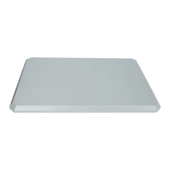
Height 0.8 in. (2.11 cm) Weight 81.1 oz. (2.3 kg) Water/Foreign Body Ingress IP67 Operational Wind 100 MPH Operating Temperature Range -40° C to 85° C Figure 1 ANT2513P4M-N front high view Cisco Aironet Four-Port Dual-Band Polarization-Diverse Antenna (AIR-ANT2513P4M-N) 78-21447-01... - Page 3 Technical Specifications 2.4 GHz Antenna Radiation Patterns 2.4 GHz Ports A&C Azimuth Plane 2.4 GHz Ports A&C Elevation Plane 2.4 GHz Ports B&D Azimuth Plane 2.4 GHz Ports B&D Elevation Plane Cisco Aironet Four-Port Dual-Band Polarization-Diverse Antenna (AIR-ANT2513P4M-N) 78-21447-01...
- Page 4 Technical Specifications 5 GHz Antenna Radiation Patterns 5 GHz Ports A&C Azimuth Plane 5 GHz Ports A&C Elevation Plane 5 GHz Ports B&D Azimuth Plane 5 GHz Ports B&D Elevation Plane Cisco Aironet Four-Port Dual-Band Polarization-Diverse Antenna (AIR-ANT2513P4M-N) 78-21447-01...
-
Page 5: Antenna And Bracket Dimensions
Technical Specifications Antenna and Bracket Dimensions Figure 2 Figure 3 show the overall dimensions of the antenna and bracket. Figure 2 Antenna and Bracket Dimensions (in millimeters) Cisco Aironet Four-Port Dual-Band Polarization-Diverse Antenna (AIR-ANT2513P4M-N) 78-21447-01... - Page 6 Technical Specifications Figure 3 Rear View of Antenna (dimensions in millimeters) Cisco Aironet Four-Port Dual-Band Polarization-Diverse Antenna (AIR-ANT2513P4M-N) 78-21447-01...
-
Page 7: System Requirements
System Requirements System Requirements This antenna is designed for use with Cisco Aironet 3702P and 1570 series access points. The antenna can be mounted on a wall, a ceiling, or a pole with a maximum diameter of 5 inches (12.7 cm). -
Page 8: Choosing A Mounting Location
(5.08 cm) and a maximum diameter of 5 inches (12.7 cm). The antenna and one mounting flange are connected together when shipped. When mounting the antenna you need to assemble the bracket hardware, connect the antenna and bracket to the mounting surface, and adjust the antenna orientation. Cisco Aironet Four-Port Dual-Band Polarization-Diverse Antenna (AIR-ANT2513P4M-N) 78-21447-01... -
Page 9: Contents Of Antenna Bracket Kit
Hose clamps (50 – 135 mm adjustment) One flange (not pictured here) ships attached to the antenna. The flange pictured here is the one Note that you attach to the wall or the pole. Cisco Aironet Four-Port Dual-Band Polarization-Diverse Antenna (AIR-ANT2513P4M-N) 78-21447-01... -
Page 10: Tools And Equipment Required
Attach the mounting bracket to the wall or ceiling using four screws or bolts and anchors through the Step 3 holes on the bracket. Figure 5 shows the wall-mount bracket. Cisco Aironet Four-Port Dual-Band Polarization-Diverse Antenna (AIR-ANT2513P4M-N) 78-21447-01... - Page 11 Installing the Antenna Figure 5 Wall-Mount Bracket and Dimensions (in millimeters) 4 slotted holes for hose clamps Assemble the bracket hardware as shown in Figure Step 4 Cisco Aironet Four-Port Dual-Band Polarization-Diverse Antenna (AIR-ANT2513P4M-N) 78-21447-01...
- Page 12 B to connector B, and so on. On the AP1570, connect antenna port A to Port 1 on the AP, antenna port B to port 2 on the AP, – and so on. Cisco Aironet Four-Port Dual-Band Polarization-Diverse Antenna (AIR-ANT2513P4M-N) 78-21447-01...
-
Page 13: Mounting On A Pole Or Mast
Suggested Cable Cisco recommends a high-quality, low-loss cable for use with the antenna, such as Cisco AIR-CAB005LL-R-N= (5 ft low-loss cable with RP-TNC and N-type connectors) for AP3702P, or AIR-CAB005LL-N= or AIR-CAB010LL-N= (5 ft and 10 ft N-type connectors, respectively) for AP1570. -
Page 14: Painting The Antenna
Cisco currently supports RSS Version 2.0. Cisco and the Cisco logo are trademarks or registered trademarks of Cisco and/or its affiliates in the U.S. and other countries. To view a list of Cisco trademarks, go to this URL: www.cisco.com/go/trademarks. Third-party trademarks mentioned are the property of their respective owners. The use of the word partner does not imply a partnership relationship between Cisco and any other company.
Need help?
Do you have a question about the AIR-ANT2513P4M-N and is the answer not in the manual?
Questions and answers