Table of Contents
Advertisement
Quick Links
Advertisement
Table of Contents

Related Manuals for Leica TPS400 Series


Summary of Contents for Leica TPS400 Series
- Page 1 Leica TPS400 Series User Manual Version 5.0 English...
- Page 2 Leica Geosys- Important paragraphs which must be tems authorized service workshop. adhered to in practice as they enable the product to be used in a technically correct and efficient manner.
- Page 3 Trademarks • Windows is a registered trademark of Microsoft Corporation All other trademarks are the property of their respec- tive owners. TPS400-5.0.1en...
- Page 4 Validity of this manual Description General This manual applies to all TPS400 Series instruments. Where there are differences between the various models they are clearly described. Telescope • When measuring distances to a reflector with EDM mode "IR" this telescope type uses a wide visible red laser beam, which emerges coaxially from the telescope's objective.
- Page 5 Contents - Overview Contents - Overview......5 System Info ........113 Contents..........6 Instrument Protection with PIN ..114 Introduction ........9 Care and Storage ......115 Operating the product...... 18 Safety Directions ......122 Measuring Preparation / Setting up 26 Technical Data ........
-
Page 6: Table Of Contents
....... 27 Area of applicability ........15 External power supply for total PC Program Package station .............. 29 Leica Geo Office Tools (LGO-Tools) ..15 Setting up the tripod ........30 Installation on the PC ........15 Instrument Setup ........... 31 Program content.......... - Page 7 FNC Key Construction ........... 80 ............43 COGO (optional) ..........82 Light On /Off ........... 43 Reference Plane (optional) ......88 Level/Plummet ..........43 Coding ............. 91 IR/ RL Toggle ..........43 Laser Pointer Settings ..........43 ............93 Free-Coding ...........
- Page 8 Technical Data Shipping ............116 ........... 143 Storage ............116 Atmospheric correction ......149 Batteries ............117 Reduction formulae ........151 Cleaning ............118 International Limited Warranty, Checking and adjusting ......119 Software License Agreement Tripod ............119 ..... 153 Circular level ..........
-
Page 9: Introduction
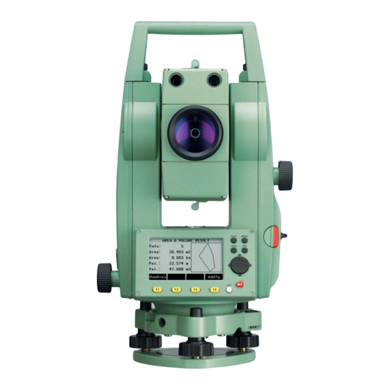
Introduction The Leica Geosystems TPS400 is a high-quality electronic total station. Its innovative technology makes the daily surveying jobs easier. The instrument is ideally suited for simple construc- tion surveys and setting out tasks. The easy operation of the instrument functions can be learned without problems in no time. -
Page 10: Special Features
Special features • Easy and quickly to learn ! • Interactive keys; with large and clear LCD. • Small, light-weight and easy-to-use. • Measurements without reflector with the inte- grated visible laser beam (TCR instruments). • Additional trigger key on side cover. •... -
Page 11: Important Parts
Important parts 1) Optical sight 2) Integrated guide light EGL (optional) 3) Vertical drive 4) Battery 5) Battery stand for GEB111 6) Battery cover 7) Eyepiece; focussing graticule 8) Focussing telescope image 9) Detachable carrying handle with mounting screws 10) Serial interface RS232 11) Foot screw 12) Objective with integrated Electronic Distance Measurement (EDM);... -
Page 12: Technical Terms And Abbreviations
Technical terms and abbreviations ZA = Line of sight / collimation axis Telescope axis = line from the reticle to the centre of the objective. SA = Standing axis Vertical rotation axis of the telescope. KA = Tilting axis Horizontal rotation axis of the telescope (Trunion axis). - Page 13 Standing axis inclination Plumb line / Compensator Angle between plumb line and Direction of gravity. The compen- standing axis. Standing axis tilt is sator defines the plumb line within not an instrument error and is not the instrument. eliminated by measuring in both faces.
- Page 14 Indicated meteorological corrected slope distance between instrument tilting axis and centre of prism/laser spot (TCR). Indicated meteorological corrected hori- zontal distance. Height difference between station and target point. Reflector height above ground Instrument height above ground Station coordinate (Easting) Station coordinate (Northing) Station height Easting of target point Northing of target point...
-
Page 15: Area Of Applicability
TPS400 Series. Program content After successful installation the following programs PC Program Package appear: Leica Geo Office Tools (LGO-Tools) Tools The program package LGO-Tools is used for the • Data Exchange Manager data exchange between the Total Station and the For data exchange of coordinates, measure- PC. - Page 16 Not using the correct upload Software can permanently damage the instrument. Before the Software Upload, always insert a charged battery into the instrument. • Format Manager For creating of own, special formatted data output files. • Configuration Manager Import/Export as well as creating of instrument configuration.
-
Page 17: Power Supply
GEB121 Power Supply GEB111 Single cells in the battery adapter GAD39 Use the Leica Geosystems batteries, chargers and accessories or accessories recommended by Leica Geosystems to ensure the correct functionality of Your Leica Geosystems instrument is powered by the instrument. -
Page 18: Operating The Product
Operating the Instrument The On / Off key is located on the side cover of the 1) Focus TPS400. Actively measured field. 2) Symbols All shown displays are examples. It is 3) Fixed keys possible that local software versions are different to Keys with firmly assigned functions. -
Page 19: Fixed Keys
Fixed keys Trigger key [PAGE] Scrolls to next page when a dialogue The measurement trigger has three settings (ALL, consists of several pages. DIST, OFF). [MENU] Accesses programs, settings, the data The key can be activated in the configuration menu. manager, adjustments, communica- tions parameters, system information Selection of Language... -
Page 20: Distance Measurement
A laser distancer (EDM) is incorporated into the may lead to incorrect distance values. instruments of the TPS400 series. Avoid interrupting the measuring beam while taking In all versions, the distance can be determined by... - Page 21 Reflectorless Be sure that the laser beam is not reflected by anything close to the line of sight (e.g. highly reflective objects). When a distance measurement is triggered, the EDM measures to the object which is in the beam path at that moment. In case of temporary obstruction (e.g.
- Page 22 Red laser to prisms Accurate measurements to prisms should be made with the standard program (Reflector EDM mode). Red laser to reflector tape The visible red laser beam can be used to measure to reflective foils, also. To guarantee the accuracy the red laser beam must be perpendicular to the reflector tape and it must be well adjusted (refer to the chapter "Checking and adjusting").
-
Page 23: Softkeys
General softkeys: Softkeys [ALL] Starts distance and angle measure- ments and saves measured values. [DIST] Starts distance and angle measure- ments without saving measured values. [REC] Saves displayed values. [ENTER] Deletes current value in the display and is ready for the input of a new value. [ENH] Opens the coordinate input mode. -
Page 24: Symbols
Status symbol "EDM type" Symbols Reflector EDM mode for measuring to Depending on software version different symbols prisms and reflective targets. are displayed indicating a particular operating Reflectorless EDM for measuring to all status. targets. A double arrow indicates choice fields. Status symbol "Battery capacity"... -
Page 25: Menu Tree
Menu tree —— File Management —— [MENU] > Confirm menu selection. —— Fixpoints —— Measurements [PAGE] Scroll to next page. —— Codes —— Initialize Memory Depending on user interface sequence and —— Memory Statistic arrangement of menu items may be different. Menu ——... -
Page 26: Measuring Preparation / Setting Up
Measuring Preparation / Setting up 1) Data cable (optional) Unpacking 2) Zenith eyepiece or eyepiece for steep angles (optional) Remove TPS400 from transport case and check for 3) Total station completeness: 4) Removable tribrach (optional) 5) Battery charger and accessories (optional) 6) Adjustment tools 7) Battery GEB111 (optional) 8) GAD105 Mini prism adapter (optional) -
Page 27: Inserting / Replacing Battery
2. Remove battery. Inserting / Replacing Battery 3. Insert battery into battery holder. 1. Remove battery holder. 4. Insert battery holder into the instrument. Insert battery correctly (note pole markings on the inside of the battery holder). Check and insert battery holder true to side into the housing. - Page 28 +20°C/+50°F to +68°F if possible. • It is normal for the battery to become warm during charging. Using the chargers recom- mended by Leica Geosystems, it is not possible to charge the battery if the temperature is too high. TPS400-5.0.1en...
-
Page 29: External Power Supply For Total Station
If you are using older cables without ferrite core, it's necessary to attach ferrite cores to the cable. If you need additional ferrite cores, please contact your local Leica Geosystems agency. The spare- part number of the ferrite core is 703 707. TPS400-5.0.1en... -
Page 30: Setting Up The Tripod
1. Loosen the clamping screws on the tripod legs, Setting up the tripod pull out to the required length and tighten the clamps. 2. In order to guarantee a firm foothold sufficiently press the tripod legs into the ground. When pressing the legs into the ground note that the force must be applied along the legs. -
Page 31: Instrument Setup
Instrument Setup Description This topic describes an instrument setup over a marked ground point using the laser plummet. It is always possible to set up the instrument without the need for a marked ground point. Important features: • It is always recommended to shield the instrument from direct sunlight and avoid Careful handling of tripod uneven temperatures around the instru-... - Page 32 Setup step-by-step 3. Turn on the instrument and switch on the laser plummet and electronic level by pressing [FNC] > [Level/Plummet]. 4. Move the tripod legs (1) and use the tribrach footscrews (6) to centre the plummet (4) over the ground point. 5.
-
Page 33: Levelling Up With The Electronic Level Step-By-Step
rotating the footscrews. When the electronic Levelling up with the electronic level level is centred the arrows are replaced by step-by-step checkmarks. 5. Centre the elec- The electronic level can be used to precisely level up tronic level for the the instrument using the footscrews of the tribrach. -
Page 34: Laser Intensity
Laser intensity Hints for positioning Changing the laser intensity External influences and the surface conditions may require the adjustment of the intensity of the laser. The laser can be adjusted in 25% steps as required. Positioning over pipes or depressions Under some circumstances the laser spot is not visible (e.g. -
Page 35: Input Mode - Method 1
Input mode - method 1 Input mode - method 2 In entry mode, enter text or numeric values. In entry mode, enter text or numeric values. PtId: PtId: 1234 5678 *ABC DEFG HIJK LMNO *ABC DEFG HIJK LMNO XYZ _ PQRS TUVW .$ ! -
Page 36: Edit Mode
Erasing characters Edit mode 1. Place cursor on character to be Existing characters are changed in the edit mode. deleted. 2. Pressing the navigation key deletes the relevant character. Info4: PREP Info4: PROP 3. Confirm input. [ESC] Deletes the change and restores the 1. -
Page 37: Inserting Characters
Inserting characters If a character was skipped (e.g. -15 instead of -125) you can insert it later. 1. Place cursor on "1". 2. Inserts an empty character on the right of "1". 3. Select range of characters /range of numbers. 4. - Page 38 Numerical input Numerical and Alphanumerical input Input is made with the softkey bar and the assigned function keys. Position the marker in the relevant field. [INPUT] 1. Calls up the input dialogue. 2. Select range of characters /range of numbers. [>>>] Additional characters / numbers.
- Page 39 Character set Entry mode contains the following characters for The character entry "*" can be used in data fields numeric and alphanumeric input. where point numbers or codes can be searched for. Signs Numerical Alphanumerical +/- In the alphanumeric character set "+" and "-" are "...
-
Page 40: Pointsearch
Pointsearch Pointsearch is a global function used by applications to e.g. find internally saved measured or fixed points. It is possible for the user to limit the point search to a particular job or to search the whole storage. The search procedure always finds fixed points before measured points that fulfill the same search criteria. -
Page 41: Wildcard Search
Wildcard search The Wildcard search is indicated by a "*". The *1 All points of any length with a "1" as the second asterisk is a place holder for any following sequence character are found (e.g.: A1, B12, A1C). of characters. A*1 All points of any length with an "A"... -
Page 42: Measuring
Example of a possible measuring display: Measuring After switching on and setting up correctly, the total station is immediately ready for measuring. In the measurement display it is possible to call up fixed keys and function keys, as well as trigger keys and their functions All shown displays are examples. -
Page 43: Fnc Key
FNC Key Under [FNC] several functions can be called up. IR: Distance measurements with prisms. Their applications are described below. RL: Distance measurements without prisms. Find more information in chapter "EDM Settings". Functions can also be started directly from the different applications. Laser Pointer Each function from the FNC menu can be Switches on or off the visible laser beam for illumi-... -
Page 44: Delete Last Record
Delete Last Record Target Offset This function deletes the last recorded data block. If it is not possible to set up the reflector directly, or This can be either a measurement block or a code it is not possible to aim the target point directly, the block. - Page 45 distance measurement has been triggered or Enter offset values! exists. The period of applicability can be set as follows: Trav. Offset: 0.600 m The offset values are reset to 0 Reset after REC Length Offset: 0.800 m after the point is saved. Height Offset: 0.500 m The offset values are applied to all...
- Page 46 Procedure: CYLINDRICAL OFFSET Hz Left 120.4361 g Hz Right 141.4435 g α 99.4658 g 15.398 m 0.0000 g TPS800_Z158 PrismOffset: 0.030 m HZL: Horizontal angle to a point on the left side of HzLeft HzRight EXIT the object HZR: Horizontal angle to a point on the right side Enter the prism offset.
-
Page 47: Height Transfer
[ALL] Completes the measurement and displays Height Transfer the results. That is the coordinates of the centre point of the cylindrical object and its radius. Example: Cylinder Offset Measure PtID POINTNUMBER Description: ----- North 638073,456 m East 436102,123 m Height 168,789 m Radius 44,350 m... -
Page 48: Hidden Point
This function determines the height of the instru- Hidden Point ment from measurements to a maximum of 5 target points, with known heights, in two faces. Example: With measurements to several targets, the improve- ment is indicated in the "delta" value. Procedure: 1. - Page 49 Procedure: 2. [All] Starts measurement and proceeds 1. Measure to first prism (P1). to the Result dialog. [All] Starts measurement and proceeds 3. Result is displayed. to step 2. [ROD] Allows you to define the rod and the HIDDEN POINT RESULT EDM-Settings.
-
Page 50: Programs
Programs [ ] Settings not made. Application pre-settings Find further information about individual These are programs that precede the application start-up programs on the subsequent pages ! programs and are used to set up and organize data Setting job collection. They are displayed after selecting an All data is saved in JOBS, like directories. -
Page 51: Setting Station
Setting Station Known Point 1. Select a PtID stored in internal memory. Each coordinate computation relates to the currently set station. 2. Input instrument height. At least plan coordinates (E, N) are required for the [OK] Sets the station. station. The station height can be entered if Set manually required. -
Page 52: Orientation
Orientation Method 2: with coordinates To determine the orientation, a target with known With the orientation, Hz-direction can be input coordinates can also be used. manually or points with known coordinates can be set. As orientation with coordinates. 2. Input of the orientation point number and to Method 1: Manual input determine the point found. - Page 53 Orientation coordinates can be either obtained from : Difference between horizontal distance to the internal memory or entered manually. target point computed from coordinates and the measured distance. The workflow is similar to Free Station workflow. After each measurement you are asked wether to Display of computed orientation proceed or not.
- Page 54 Displaying residuals [RESID] Display of residuals. 1) Actual 2) Design Height correction correction of the horizontal distance Correction of Hz-angle. TPS400-5.0.1en Programs...
- Page 55 Useful information • If the orientation is only measured in telescope position II the Hz-orientation is based on tele- scope position II. If measured only in telescope position I or mixed the Hz-orientation is based on telescope position I. • The prism height may not be changed during measurements in the first and second telescope position.
-
Page 56: Applications
[MENU] 1. Press the [MENU] fixed key. Applications 2. Selecting the "Program" option. Introduction 3. Calling up applications and acti- Applications are predefined programs, that cover a vating start programs. wide spectrum of surveying duties and facilitate [PAGE] Scroll to next page. daily work in the field. -
Page 57: Surveying
Two coding methods are available: Surveying 1. Simple coding = remark: With the program Surveying the measurement of an Input a code/remark in the relevant field. These unlimited number of points is supported. It is compa- text is stored with the corresponding measure- rable to "Meas &... -
Page 58: Stake Out
Stake out Polar Stake out Normal indication of polar stake out offsets Hz, This program calculates the required elements to stakeout points from coordinates or manually entered angles, horizontal distances and heights. Setting out differences can be displayed continu- ously. Setting out coordinates from memory Procedure: Select the point. - Page 59 Orthogonal Stake out Cartesian Stake out The position offset between measured point and Setting out is based on a coordinate system and the stake out point is indicated in a longitudinal and offset is divided into a north and east element. transversal element.
-
Page 60: Free Station
The following measurements sequences to Free Station target points are possible: The application "Free Station" is used to determine 1. Hz- and V-angles only (resection) the instrument position from measurements to a 2. Distance and Hz- and V-angle (3 point minimum of two known points and a maximum of resection) five known points. - Page 61 Measuring facilities Computation procedure Single face I or II or dual face I + II measurements The measuring procedure automatically determines are always possible. No specific point sequence or the method of evaluation, e.g. resection, 3 point specific face sequences are required. resection, etc.
- Page 62 Procedure: Here you can enter a limit for the standard deviation values. If your computed deviation exceeds the limit a warning dialog appears, where you can decide wether to proceed or not. 1. Input of the name of the station and the height of the instrument.
- Page 63 [AddPt] Input another backsight point. Results [COMPUTE] Calculates and displays the station Displays calculated station coordinates: coordinates, if at least 2 points and a distance were measured. STATION COORDINATES Indicates that the third point in tele- scope position I was measured. Station 3/I II Indicates that the third point in tele-...
- Page 64 If the instrument height was set to 0.000 in This dialog shows the computed residuals: the setup screen, then the station height refers to Residual = Calculated value - Measured value height of trunnion axis. Displays standard deviations: TARGET RESIDUALS 3/3 STATION STANDARD-DEVITION PtID...
- Page 65 [Disable]/[Enable] Excludes/includes the displayed point from/in the calculations. Recalculates the free station and displays the station standard devia- tion. Press [PREV] to display the new station coordinates. [StdDev] Displays standard deviation. With the function keys, scroll between the residuals of the indi- vidual backsight points.
- Page 66 Warnings / Messages Important messages Meaning This message occurs if the selected target point has no easting or northing Selected point has no valid data ! coordinate. If 5 points have already been measured and another point is selected. The Max 5 points supported ! system supports a maximum of 5 points.
-
Page 67: Reference Line
[ENH] Manually input coordinates. Reference Line [LIST] Displays the list of available points. This program facilitates the easy stake out or checking of lines for buildings, sections of road, simple excavations, etc. Analogue procedure for the second base point. A reference line can be defined by referencing a known base line. - Page 68 Off: Parallel offset 2. Shifting/Rotating the Base line The base line can be offset longitudinally, parallel Longitudinal offset and vertically or rotated. This new line is called the Rotation parameter reference line. All measured data refers to the refer- Input of the parameters: ence line.
- Page 69 3. Selecting the subapplication REFERENCE LINE - MAIN 1/2 [MEASURE] Starts the subapplication to measure Length 14.872 m Line & Offset (see issue 4). Enter values to shift line: [STAKE] Starts the subapplication to stake Offset 1.000 m out (see issue 5). Line 0.500 m Height...
- Page 70 REFERENCE LINE PtID 1.500 m Offset: 0.208 m Line 0.349 m 1.203 m DIST TPS800_Z38 The height of the first reference point is always used 1RP: 1st reference point as the reference height for the calculation of the Measured point height differences ( Reference line Longitudinal offset...
- Page 71 Example "relative to first reference point" 5. "Stake out" subapplication You can enter longitudinal, parallel and height offsets for the target points to be set-out relative to the reference line. The program calculates the differ- ence between a measured point and the calculated point.
- Page 72 Example "orthogonal stake out" Display in "Stake out" measure mode: ORTHOGONAL STAKEOUT 1/2 PtID 1.500 m +0.200 g 2.368 m 0.260 m DIST TPS800_Z40 Offset: 2.040 m Line 1.203 m 1RP: 1st reference point 0.260 m Reference line The signs for the distance and angle differences are Measured point correction values (required minus actual).
-
Page 73: Tie Distance
The stake out point is higher than the Tie Distance measured point. The application Tie Distance computes slope distance, horizontal distance, height difference and azimuth of two target points measured online, Warnings / Messages selected from the Memory or entered using the Keypad. - Page 74 Radial Method: 3. Result is displayed. Azimuth between point1 and point2. Slope distance 1-2 Slope distance between point1 and Slope distance 1-3 point2. Horizontal distance between point1 and point2. Height difference between point1 Centre point and point2. Grade Grade [%] between point1 and point2.
- Page 75 Softkeys - radial method: [NewPt 1] Determine new central point. [NewPt 2] Determine new radial point. [POLY] Switch to polygonal method. Programs TPS400-5.0.1en...
-
Page 76: Area & Volume
Area & Volume The application program Area is used to compute online areas of max. 50 points connected by straights. The target points have to be measured, selected from memory or entered via keyboard in clockwise direction. The calculated area is projected onto the horizontal plane (2D) or projected onto the sloped reference plane defined by 3 points (3D). - Page 77 1. Determine area points 2. Results [ALL] Starts the measurement to the [Def. 3D] To define the sloped reference point. plane by selecting or measuring three points. [FIND] / Searches for point in internal [LIST] memory. [VOLUME] To calculate a volume with constant height.
- Page 78 P0 Station P1 Target point which defines the sloped reference plane P2 Target point which defines the sloped reference plane P3 Target point which defines the sloped reference plane P4 Target point Constant height Perimeter (3D), polygonal length from the start point to the current measured point of the area (3D) TPS800_Z101...
-
Page 79: Remote Height
Procedure: Remote Height 1. Input PtID and reflector height Points directly above the base prism can be deter- [ALL] Starts measurement to base point mined without a prism at the target point. and continues to 2. [hr?] Starts the program that determines an unknown reflector height. -
Page 80: Construction
Construction This application allows to define a construction site PtID : by combining set-up of the instrument along a construction line, measuring and setting out points in relation to the line. 1.500 m 7.225 m After selecting the application you have two options: Off: 10.194 m... - Page 81 Measured point height is above line start point’s The graphics show you the position of the prism height. related to the stake out point. Below, the exact The height of the line start point is always values are displayed, combined with arrows to show used as the reference height! the direction.
-
Page 82: Cogo (Optional)
During use of the application the previous COGO (optional) Orientation and Station parameters will be replaced The application COGO can be started in by the new calculated ones. total 15 times for trial. Afterwards you have to enter the license code. COGO is an application program to perform coordi- nate geometry calculations such as: •... - Page 83 Traverse Inverse & Traverse Inverse TPS800_Z87 TPS800_Z86 Known P1 Known point Known Direction from P1 to P2 P1 First known point d1 Distance between P1 and P2 P2 Second known point d2 Positive offset to the right Unknown d3 Negative offset to the left Direction from P1 to P2 Unknown d1 Slope distance between P1 and P2...
- Page 84 Bearing - Distance Intersections Bearing - Bearing TPS800_Z89 TPS800_Z88 Known P1 First known point Known P2 Second known point P1 First known point Direction from P1 to P3 and P4 P2 Second known point Radius, as defined by the distance from P2 to a1 Direction from P1 to P3 P4 and P3 a2 Direction from P2 to P3...
- Page 85 Distance - Distance By Points TPS800_Z90 TPS800_Z91 Known Known P1 First known point P1 First known point P2 Second known point P2 Second known point r1 Radius, as defined by the distance from P1 to P3 Third known point P3 or P4 P4 Fourth known point r2 Radius, as defined by the distance from P2 to Line from P1 to P2...
- Page 86 Set Point by ... Offset Distance - Offset TPS800_Z93 TPS800_Z92 Known P1 Baseline start point Known P2 Baseline end point P1 Baseline start point Difference in length/abzissa (HD) P2 Baseline end point Lateral deviation/ordinate (Offset) P3 Lateral point Unknown Unknown P3 Lateral point d1 Difference in length/abzissa (HD) d2 Lateral deviation/ordinate (Offset)
- Page 87 Plane Offset Extension The "Extension" routine computes extend point from base line. ΔL1 ΔL2 TPS800_Z159 Known Baseline start point Known Baseline end point P1 Point 1 which defines plane L1 or Distance P2 Point 2 which defines plane Unknown P3 Point 3 which defines plane P2, P4 Extended point P4 Offset point...
-
Page 88: Reference Plane (Optional)
• The first point is the origin of a local coordinate Reference Plane (optional) system. The application Reference Plane can be • The second point defines the direction of the trialed 15 times. Afterwards it is necessary to enter local Z-axis. the license code. - Page 89 Measured point. This point is probably not The perpendicular distance to the plane can be posi- located on the plane. tive or negative: Footprint point of the perpendicular vector from P4 to the defined plane. This point is definitely located on the defined plane. X-axis of local coordinate system Z-axis of local coordinate system Off+...
- Page 90 [LIST] Displays the list of available points. Procedure [ENH] Opens the coordinate input mode. 1. Measuring points defining the reference plane PLANE 1/3 2. Measuring target point Measure a target point as you usually survey points. Measure 1st plane point ! Point 1 Point 2 -----...
-
Page 91: Coding
Offset: Calculated perpendicular distance Coding between target point and plane (intersection point). Codes contain information about recorded points. With the help of coding, points can be assigned to a Perpendicular distance from the particular group simplifying later processing. intersection point to the local Z-axis. More information on coding can be found under Perpendicular distance from the "Data management". - Page 92 Individually entered code blocks are not added to the code list. Exceptions: Leica Geo Office Tools (LGO-Tools) With the codelist editor of LGO/LGO-Tools a status Codelists can be easily created and uploaded to the can be assigned to the attributes.
-
Page 93: Settings
Settings This menu enables extensive user-specific settings • Zenith: Zenith=0°; Horizon=90° in order to adapt the instrument to their own require- • Horizon: Zenith=90°; Horizon=0° ments. • V-(%): 45°=100%; Horizon=0° Contrast The % value increases rapidly. "--.--%" Setting the display contrast in 10% steps. appears on the display above 300%". - Page 94 Sector Beep Sector Beep switched off Sector Beep sounds at right angles (0°, 90°, 180°, 270° or 0, 100, 200, 300 gon) Example Sector Beep: From 95.0 to 99.5 gon (or from 105.0 to 100.5 gon) a "Fast beep" sounds whilst from 99.5 to 99.995 gon (or from 100.5 to 100.005 gon) a "Permanent beep"...
- Page 95 Beep DSP Heater The beep is an acoustic signal after each key stroke. Is automatically activated when the display illumination is on and the instru- Beep switched off ≤ ment temperature is 5°C. Normal Normal volume Loud Increased volume Language The current loaded languages are shown.
- Page 96 Intern All data is recorded in the internal If option "Hz Collimation ON" is active, each memory. measured Hz-angle is corrected (depending on V-angle). For normal operation the Hz-collimation remains switched on. GSI 8/16 Select GSI output format. More information on Hz-collimation can be GSI 8: 81..00+12345678 found under "Adjusments".
- Page 97 possible angle values: 0 gon to 399.999 • Method 1 Standard method • Method 2 possible angle values: 0 to 6399.99mil Advanced method The setting of the angle units can be changed at any Distance Unit time. meter Meter The actual displayed values are converted ft-in1/16 US-feet-Inch-1/16 inch according to the selected unit.
-
Page 98: Edm Settings
EDM Settings The EDM-settings contain a detailed menu with EDM Mode selection boxes. With TCR instruments different settings for measurements with reflectorless (RL) and reflector (IR) EDM mode are available. Depending on selected measuring mode the selec- tion prism types are different. Fine measuring mode for high precision measurements with IR-Fine... - Page 99 With the RL-EDM each object in the beam is Miniprism measured (possibly also branches, cars, etc.). +17.5 GMP101/102 Prism type Calling the function in the EDM settings. JPMINI +34.4 Mini prism Leica Constants Reflective +34.4 Prisms [mm] targets is set at "Prismconst" Standard USER (-mm + 34.4;...
- Page 100 Prism Constant Calling the function in the EDM settings. Entry of a user specific prism constant. Input can only be made in [mm]. Limit value: -999,9 mm to +999,9 mm Laser Pointer Off: Visible laser beam is switched off. Visible laser beam for visualising the target point is switched on.
- Page 101 [SCALE] [ATMOS] Scale of projection. Input of atmospheric parameters. Atmospheric Parameters (ppm): Distance measurement is influenced directly by the atmospheric conditions of the air in which distance measurement are taken. Scale factor: Entering the scale of projection. Measured values and coordinates are corrected with the PPM param- eter.
- Page 102 • Ht. a. MSL Height above sea level at instrument location. • Temperature Air temperature at instrument location. • Pressure Air pressure at instrument location. • Atmos PPM: Calculated and indicated atmospheric PPM. Signal [SIGNAL] Displays EDM signal strength (reflection strength) in steps of 1%.
-
Page 103: File Management
File Management The File Manager contains all functions for entering, editing and for checking data in the field. Jobs are a summary of data of different types, e.g. fixed points, measurements, codes, results, etc. The job definition consists of the input of job name and user. - Page 104 Fixpoints Valid fixed points contain at least the PtID and the coordinates (E, N) or (H). [DELETE] Deletes selected fixed point. [FIND] Starts point search. Exact PtIDs can be entered or the * wildcard-criteria used. [NEW] Opens input for PtID and coordi- nates.
- Page 105 [DELETE] Starts deleting process within the selected area. [ALL] Deletes all data in memory. All data will be lost ! Deleting the memory cannot be undone. After confirming the message all data is deleted permanently. Memory Statistic Displays job specific memory information such as: •...
-
Page 106: Start-Up Sequence
Start-up sequence Sets the screen the instrument starts in when Procedure: switched on. E.g. the electronic bubble can be After confirming the dialogue of notification, the displayed at every start. "Meas & Rec" screen is displayed. A maximum of 16 of the next key presses are stored. -
Page 107: Calibrations
Calibrations Determining Line-of-sight error and V-Index These errors should be determined before The calibration contains the determination of the the instrument is used for the first time, before preci- following instrument errors: sion surveys, after long periods of transport, before and after long periods of work, and if the tempera- •... -
Page 108: Line-Of-Sight Error (Hz-Collimation)
Line-of-sight error (Hz-collimation) V-Index (Vertical index error) The line-of-sight error or collimation error (C) is the The vertical circle should read exactly 90° (100 gon) deviation from the perpendicular between the tilting when the line of sight is horizontal. Any deviation axis and the line of sight. - Page 109 4. Change telescope position and aim to the point Hz-collimation again. V-index For checking the horizontal aiming Hz and V are Display adjustment value: displayed. Summarizes saved values. Procedure: 1. Level instrument with electronic bubble. 2. Aim at a point approximately 100m from the instrument which is within 5°...
- Page 110 Warnings / Messages Important Messages Meaning Measures Aim on the target point with an accuracy of V-Angle not suitable for Aiming tolerance not met or telescope posi- min. 5 gon. The target point must be calibration (Check V-angle tion/face not changed. approximately in the horizontal plane.
-
Page 111: Comm Parameters
Carriage return communication parameters of the serial interface Stopbits RS232 must be set. Fixed setting 1. Leica Standard setting Interface plug connections: 19200 Baud, 8 Databit, No Parity, 1 Stopbit, CR/LF Baudrate Data transfer speed 2400, 4800, 9600, 19200 [bits / second] Databits Data transfer is realized with 7 databits. -
Page 112: Data Transfer
(no protocol). Data: Select the data range to be transferred GSI-ID’s (measurements, fixed points) PtID Format: Select output format. Select Leica-GSI- Horizontal direction format, or your own format created in Vertical angle the "Format Manager" and transfer to Orientation the LGO/LGO-Tools. -
Page 113: System Info
System Info Displays helpful information and date / time are set. [SW-Info] The software of the instrument is composed of different software pack- • Battery ages. Depending on the package, Remaining battery power (e.g. 40%). different versions are possible. • Instr.Temp. -
Page 114: Instrument Protection With Pin
Instrument Protection with PIN The instrument can be protected by a Personal by pressing [FNC] > Lock with PIN without switching Identification Number. If the PIN protection is acti- off the instrument vated, the instrument will always prompt for a PIN code entry after starting up. -
Page 115: Care And Storage
Care and Storage In the field Transport When transporting or shipping the equipment always use the original Leica Geosystems pack- aging (transport case and shipping cardboard). After a longer period of storage or transport of your product always check the field adjustment parameters indicated in this manual before using the product. -
Page 116: Inside Vehicle
It must always be transported in its case and be properly secured. Shipping For shipping the product by rail, aircraft or ship use the Leica Geosystems original packaging (transport case or shipping cardboard) or another suitable packaging securing the product against blows and vibrations. -
Page 117: Batteries
Batteries • Refer to Technical Data for information about storage temperature range. • A storage temperature range of 0°C to +20°C / +32°F to +68°F in a dry environment is recom- mended to minimize self-discharging of the battery. • At the recommended storage temperature range, batteries containing a 10% to 50% charge can be stored for up to one year. -
Page 118: Cleaning
Fogging of prisms: Cleaning Reflector prisms that are cooler than the ambient temperature tend to fog. It is not enough simply to wipe them. Keep them for some time inside your jacket or in the vehicle to allow them to adjust to the ambient temperature. -
Page 119: Checking And Adjusting
Circular level Checking and adjusting Tripod Level-up the instrument in advance with the elec- tronic level. The bubble must be centered. If it The connections between metal and timber compo- extends beyond the circle, use the Allen key nents must always be firm and tight. supplied to center it by turning the adjustment •... -
Page 120: Circular Level On The Tribrach
Under normal circumstances setting of the laser plummet is not necessary. If an adjustment is necessary due to external influences the instrument has to be returned to any Leica service department. Checking by turning the instrument by 360°: 1. - Page 121 Depending on brightness and surface the size of the laser spot can vary. At a distance of 1.5 m an average value of 2.5 mm diameter must be esti- mated. The maximum diameter of the circular movement described by the centre of the laser point should not exceed 3 mm at a distance of 1.5 m.
-
Page 122: Safety Directions
Safety Directions The following directions should enable the person Intended Use responsible for the product, and the person who actually uses the equipment, to anticipate and avoid Permitted use operational hazards. • Measuring horizontal and vertical angles. The person responsible for the product must ensure •... -
Page 123: Limits Of Use
Limits of Use damages or defects. • Use with accessories from other manufacturers Environment without the prior express approval of Leica Suitable for use in an atmosphere appropriate for Geosystems. permanent human habitation: not suitable for use in • Aiming directly into the sun. -
Page 124: Responsibilities
To understand the safety instructions on the Leica Geosystems AG, CH-9435 Heerbrugg, here- product and the instructions in the user manual. inafter referred to as Leica Geosystems, is respon- • To be familiar with local regulations relating to sible for supplying the product, including the user safety and accident prevention. -
Page 125: Hazards Of Use
WARNING dangerous to use poles and extensions in the Using a battery charger not recommended vicinity of electrical installations such as power by Leica Geosystems can destroy the batteries. This cables or electrical railways. can cause fire or explosions. Precautions: Precautions: Keep at a safe distance from electrical installations. - Page 126 the safety authorities responsible for the electrical WARNING installations and follow their instructions. During dynamic applications, for example stakeout procedures there is a danger of accidents occurring if the user does not pay attention to the environmental conditions around, for example obstacles, excavations or traffic.
- Page 127 Adhere to the instructions given by the computer Protect the batteries from mechanical influences manufacturer with regard to field use in conjunction and high ambient temperatures. Do not drop or with Leica Geosystems products. immerse batteries into fluids. CAUTION WARNING...
- Page 128 Always prevent access to the product by unauthorized personnel. Product specific treatment and waste management information can be downloaded from the Leica Geosystems home page at http://www.leica- geosystems.com/treatment or received from your Leica Geosystems dealer.
-
Page 129: Laser Classification
if used and operated as defined in this user manual Laser classification due to the low eye hazard level. General Products classified as laser class 2 or class 3R may cause dazzle, flashblindness and afterim- ages, particularly under low ambient light conditions. The following directions (in accordance with the state of the art - international standard IEC 60825-1 (2007-03) and IEC TR 60825-14 (2004-02)) provide... - Page 130 Description Value Maximum average radiant power 0.33 mW Pulse duration 800 ps Pulse repetition frequency 100 MHz - 150 MHz Wavelength 650 nm - 690 nm Safety Directions TPS400-5.0.1en...
- Page 131 Labelling Type: TC..Art.No.: ..Power: 12V/6V ---, 1A max Leica Geosystems AG CH-9435 Heerbrugg Manufactured: ..S.No.: ..Complies with 21 CFR 1040.10 and 1040.11 except for deviations pursuant to Laser Notice No.50, dated July 26,2001. This device complies with part 15 of the FCC Rules.
-
Page 132: Distancer, Measurements Without Reflectors (Rl Mode)
c) natural aversion behaviour for exposure to Distancer, Measurements without Reflectors bright light for the case of visible radiation. (RL mode) The EDM module built into the product produces a visible laser beam which emerges from the tele- Description Value (R400/R1000) scope objective. - Page 133 WARNING Potential hazards are not only related to direct beams but also to reflected beams aimed at reflecting surfaces such as prisms, windows, mirrors, metallic surfaces etc. Precautions: Do not aim at areas that are essentially reflective, such as a mirror, or which could emit unwanted reflections.
- Page 134 Labelling Laser Aperture Laser Radiation Avoid direct eye exposure Class 3R Laser Product according to IEC 60825-1 ( 2007 - 03 ) Po ≤ 5.00 mW λ = 650 - 690 nm a) Laser beam Safety Directions TPS400-5.0.1en...
- Page 135 Type: TC..Art.No.: ..Power: 12V/6V ---, 1A max Leica Geosystems AG CH-9435 Heerbrugg Manufactured: ..S.No.: ..Complies with 21 CFR 1040.10 and 1040.11 except for deviations pursuant to Laser Notice No.50, dated July 26,2001. This device complies with part 15 of the FCC Rules.
-
Page 136: Electronic Guide Light Egl
Electronic Guide Light EGL The integrated Electronic Guide Light produces a visible LED beam from the front side of the tele- scope. Depending on the type of telescope the EGL may be designed differently. The product described in this section, is excluded from the scope of IEC 60825-1 (2007-03): "Safety of laser products". -
Page 137: Laser Plummet
WARNING Laser plummet From a safety perspective class 2 laser The laser plummet built into the product produces a products are not inherently safe for the eyes. visible red laser beam which emerges from the Precautions: bottom of the product. Avoid staring into the beam or pointing the beam at other people. - Page 138 Labelling Laser Radiation Do not stare into beam Class 2 Laser Product according to IEC 60825-1 ( 2007-03 ) ≤ 1.00 mW λ = 620 - 690 nm a) Will be replaced by a Class 3R warning label if applicable Safety Directions TPS400-5.0.1en...
-
Page 139: Electromagnetic Compatibility Emc
Electromagnetic radiation can cause distur- bances in other equipment. Although the product meet the strict regulations and standards which are in force in this respect, Leica Geosystems cannot completely exclude the possi- 1) Exit for laser beam bility that other equipment may be disturbed. - Page 140 WARNING Use only the equipment and accessories recom- If the product is operated with connecting mended by Leica Geosystems. When combined cables attached at only one of their two ends, for with the product, they meet the strict requirements example external supply cables, interface cables, stipulated by the guidelines and standards.
-
Page 141: Fcc Statement (Applicable In U.s.)
WARNING tial installation. Changes or modifications not expressly approved by Leica Geosystems for compliance This equipment generates, uses and can radiate could void the user's authority to operate the equip- frequency energy and, if not installed and used in ment. - Page 142 Labelling: ....: ................
-
Page 143: Technical Data
Technical Data Telescope Display resolution • Transit fully gon ............0.0005 • Magnification:..........30x 360d ............0.0005 • Image: ........... upright 360s ..............1" • Free Objective aperture: ....... 40 mm mil ............. 0.01 • Shortest focussing distance: ..1.7 m (5.6 ft) Level sensitivity •... - Page 144 Laser plummet Dimensions • Location: ....in vertical axis of instrument • Instrument: ............• Accuracy: ........Deviation from Height (including tribrach and carrying handle): ..........plumbline 1.5 mm - with tribrach GDF111................. (2 sigma) at 1.5 m ..........360 mm ± 5 mm ..........
- Page 145 • External supply Recording (via serial interface) • RS232 interface ......... Yes ......If an external cable is used, • Internal Memory ........Yes ......then the voltage range must lie Total capacity........768 KB ......≈ 12500 measurements or ........between 11.5V and 14V.
- Page 146 Distance measurement (IR: Reflector mode) Range: (normal and rapid measurement) Principle: Phase measurement Tape Standard 3 prisms 360° Mini 360° Mini Type: Coaxial, visible red laser 60mm x prism (GPH3) reflector prism prism 60mm Class 1 1800 m 2300 m 800 m 150 m 800 m...
- Page 147 Distance measurement (RL: Reflectorless mode) Power: Range (without reflector) Measuring System analyser basis 100 MHz - Atmospheric No reflector No reflector system: 150 MHz conditions (white target)* (grey, albedo 0.25) Type: Coaxial, visible red laser Class 3R 200 m (600 ft) 100 m (330 ft) Carrier wave: 658 nm...
- Page 148 Distance measurement RL-prism (with reflector) Accuracy Time per • Range of measurement: ..from 1000m up measuring measurement • Display unambiguous: ....... to 12 km program Standard** Ultra & Power: Range (with reflector) 0 - 500 m 2 mm + 2 ppm typ.
-
Page 149: Atmospheric Correction
Atmospheric correction The distance displayed is correct only if the scale correction in ppm (mm/km) which has been entered corresponds to the atmospheric conditions prevailing at the time of the measurement. The atmospheric correction takes air pressure and air temperature into account. For utmost precision in distance measurements, atmospheric correction must be determined with 1 ppm accuracy, air temperature to 1°C and air pres-... - Page 150 Atmospheric correction in ppm with °C, mb, H Atmospheric correction in ppm with °F, inch Hg, (metres) at 60% relative humidity H (feet) at 60% relative humidity Technical Data TPS400-5.0.1en...
-
Page 151: Reduction Formulae
The instrument calculates slope distance, horizontal Reduction formulae distance and height difference in accordance with the following formula. Earth curvature and mean refraction coefficient (k = 0.13) are taken into account automatically. The calculated horizontal distance relates to the station height, not to the reflector height. - Page 152 ζ · |sin ζ · cos ζ vertical-circle reading 1.47 · 10 6.83 · 10 0.13 6.37 · 10 TPS400-5.0.1en Technical Data...
-
Page 153: International Limited Warranty, Software License Agreement
International Limited Warranty which on the product, or that is supplied to you on a data you can download from the Leica Geosystems carrier medium, or that can be downloaded by you home page at http://www.leica-geosystems.com/... - Page 154 Leica Geosystems distributor. You must not install or use the software unless you have read and accepted the terms and conditions of the Leica Geosystems Software License Agree- ment. Installation or use of the software or any part thereof, is deemed to be an acceptance of all the terms and conditions of such license agreement.
-
Page 155: Index
Index Baudrate ............111 Beep ..............95 Abbreviations ............. 12 Brg ..............74 Additional characters ......... 39 Adverse uses ........... 122 Alphanumerical input ......... 38 Calibration ............107 Angle measurement ........143 Care and Storage ..........115 Angle Unit ............96 Cartesian Stake out ........... - Page 156 Contrast ............. 93 EGL ..............100 Coordinate Editor ..........15 Electromagnetic acceptability ......139 Cylinder Offset ........... 45 Electronic Guide Light EGL ......136 Electronic level ..........32, 33 Endmark ............111 Data Exchange Manager ........15 Erasing characters ..........36 Data Output ............
- Page 157 GSI-coding ............91 Interface plug connections ......111 GSI-ID’s ............112 Intersections ............84 Guide Light ............100 Bearing - Bearing ..........84 Bearing - Distance ..........84 By Points ............85 Hazards of use ..........125 Distance - Distance ........... 85 Height determination of remote points ....
- Page 158 Navigation keys ..........18 Laser Pointer ........... 100 No. of measurements ........145 Laserpointer ............43 Numerical input ..........38 Leica Geo Office Tools ........ 15, 92 Level ..............33 Offset ............24, 86 Level sensitivity ..........143 Distance - Offset ..........86 Level/Plummet ...........
- Page 159 Parity ............... 111 Reference Plane ......... 56, 88 Permitted uses ..........122 Reflective targets ..........99 PIN ............44, 114 Responsibilities ..........124 Plane Offset ............87 Reticle ............... 13 Plumb line ............13 Reticle Illumin............ 95 Pointsearch ............40 RL ..............
- Page 160 Software Upload ..........15 Tilting axis ............12 Stake out ............58 Tilting axis height ..........144 Standard prism ..........99 Time ..............113 Standing axis ............. 12 Transport ............115 Standing axis inclination ........13 Traverse ............83 Start programs ........... 50 Tribrach ...........
- Page 161 Zenith ..............13 Zenith angle ............12 Index TPS400-5.0.1en...
- Page 162 International Standards of Quality Management and Quality Systems (ISO standard 9001) and Environmental Management Systems (ISO standard 14001). Ask your local Leica dealer for more information about our TQM program. Leica Geosystems AG Heinrich-Wild-Strasse CH-9435 Heerbrugg Switzerland Phone +41 71 727 31 31 www.leica-geosystems.com...
Need help?
Do you have a question about the TPS400 Series and is the answer not in the manual?
Questions and answers