
Related Manuals for Emerson Machinery Health Expert CSI 2600


Summary of Contents for Emerson Machinery Health Expert CSI 2600
- Page 1 User Guide MHM-97453, Rev 1 April 2014 ™ CSI 2600 Machinery Health Expert User Guide...
- Page 2 Information in this document is subject to change without notice and does not represent a commitment on the part of Emerson Process Management.
-
Page 3: Table Of Contents
Contents Contents Chapter 1 CSI 2600 Machinery Health Expert ..................1 CSI 2600 overview ........................1 User Guide overview ........................1 User Guide conventions ......................2 Technical support ........................2 Chapter 2 Introduction to the CSI 2600 ...................3 CSI 2600 out of the box ....................... 3 Optional services ......................... - Page 4 Contents Chapter 6 Data collection and analysis ..................61 View or edit IP addresses with the unit ..................61 Verify or assign IP addresses to the database ................62 Database configuration: overview ..................... 62 Online Watch overview ......................66 Archive management ........................ 69 Create archives manually ......................70 Disable archive predicates ......................
-
Page 5: Csi 2600 Machinery Health Expert
The CSI 2600 is available with one or two 6510 signal input modules. Each 6510 module has 12 analog channels, 2 tachometer channels, and 2 relay channels. Emerson sells the CSI 2600 as a 12/2/2 channel or a 24/4/4 channel analyzer. -
Page 6: User Guide Conventions
Be at your computer when you call. We can serve you better when we can work through the problem together. Software Technical Support Emerson provides technical support through the following for those with an active support agreement: • Telephone assistance and communication via the Internet. -
Page 7: Introduction To The Csi 2600
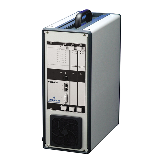
Introduction to the CSI 2600 Introduction to the CSI 2600 Topics covered in this chapter: • CSI 2600 out of the box • Optional services • CSI 2600 monitoring requirements • Precautions • Safety notes CSI 2600 out of the box Figure 2-1: CSI 2600 front view MHM-97453, Rev 1... - Page 8 Introduction to the CSI 2600 Figure 2-2: CSI 2600 back view MHM-97453, Rev 1...
- Page 9 Introduction to the CSI 2600 Figure 2-3: CSI 2600 accessories • CSI 4500/6500/2600 Machinery Health Monitor firmware DVD • AMS Suite Operating Manuals & Extras DVD • 1 Ethernet cable • 1 serial cable • 1 package of replacement filters •...
-
Page 10: Optional Services
Introduction to the CSI 2600 • Mounting pads • BNC connectors • Extension cords Optional firmware • PeakVue • Modbus Optional software • Object Linking and Embedding for Process Control (OPC) Optional services • Training in the Online Prediction Operation and Maintenance course and rolling element bearing vibration. -
Page 11: Safety Notes
Place the device on a solid, stable surface when not in use and do not place any heavy objects on it. • Use only accessories recommended by Emerson Process Management. • Keep liquids and foreign objects away from your CSI 2600. - Page 12 Introduction to the CSI 2600 MHM-97453, Rev 1...
-
Page 13: Chapter 3 Getting Started
Getting started Getting started Topics covered in this chapter: • Remove the CSI 2600 from the case • Turn on the CSI 2600 • Turn off the CSI 2600 • CSI 2600 fuse access • Data collection overview • Data recorder modes •... -
Page 14: Turn On The Csi 2600
Getting started Figure 3-1: Remove the CSI 2600 from the case Turn on the CSI 2600 The CSI 2600 has two toggle switches, and both must be toggled in order to turn the unit on and off. Prerequisites WARNING! Ensure that physical contact with unbuffered sensor signals will not interfere with other monitoring or protection systems. -
Page 15: Turn Off The Csi 2600
Getting started Turn off the CSI 2600 Prerequisites Make sure that the computer has been connected long enough to allow all of the desired data to be transferred to the computer for storage. Check the time stamps of the data being reported in Online Watch. -
Page 16: Data Collection Overview
Getting started Data collection overview The CSI 2600 is a continuously monitoring online system. Once configured, it will collect both periodic predictive data (Trend, Spectra, and Waveform snapshots, multiplexed two channels at a time) and Transient measurements (continuous unbroken waveforms for extended periods on up to all 24 channels). -
Page 17: Store Data On A Nas Hard Drive
Getting started With the computer disconnected, the periodic predictive data is also buffered in the CSI 2600’s internal RAM. The amount of time it will take to fill up the CSI 2600’s internal RAM depends on how periodic predictive data storage settings are configured in the database. This data will also begin to FIFO when the memory buffer is full. -
Page 18: Network Configuration
Getting started Figure 3-3: Online Configuration—External Network Folder Specifications Table 3-1: External Network Folder Specifications dialog fields Field Values Explanation UNC Path (variable) Specifies the to the NAS drive folder where the unit should stream transient data. Allowed Drive Space 1–250 GB Specifies the limit for transient data on the NAS drive. -
Page 19: System Architecture
Getting started Table 3-2: Example CSI 2600 system IP addresses CSI 2600 Main Processor IP 192.168.0.10 CSI 2600 Transient Processor IP 192.168.0.11 Computer IP 192.168.0.1 Notes • The IP addresses shown are defaults. If two or more systems will be used, each should be given a unique IP address. - Page 20 Getting started Figure 3-4: Online database diagram Collection criteria • Analysis Parameter (AP) Set—Defines a particular way to collect spectral data, and specifies: the number of lines of resolution. any averaging modes and windowing. whether to be order-based. what FMax to use. what parameters are to be collected.
- Page 21 Getting started Online storage logical hierarchy • Area—A user-defined grouping of equipment. An area often corresponds to a building or section of a process line within a plant. • Equipment—A group of coupled devices that logically should be monitored together. Most often a machine train is made up of a driver component (such as a motor) and one or more driven components (such as a pump or fan).
-
Page 22: Access The Termination Board
Getting started An analyst must know the sensitivity and offset of signals connected to the CSI 2600, which may be the same (or different) as signals connected to existing modules. An analyst must also know if the CSI 2600 connections are to buffered or unbuffered field wiring or module outputs. -
Page 23: Connectivity
Getting started 3.11 Connectivity The CSI 2600 monitoring unit consists of: • An AC power connection (110–220 V, 50/60 Hz) • An Ethernet connection • Signal connections for 1–24 sensors • Tachometer connections for 1–4 sensors • Digital I/O relay connections for 1–4 relays •... - Page 24 Getting started Figure 3-6: Ethernet ports The NIC and Hub ports are located on the unit's faceplate. 3.11.3 Channel connections The CSI 2600 offers up to 24 sensor channels. The connections are made through the BNC connectors on the rear of the CSI 2600. In addition, the CSI 2600 offers up to 4 tach channel connections, up to 4 digital relay channel connections, and 1 Ethernet HUB and 1 NIC.
- Page 25 Radial Trip and Axial Thrust predicates are special methods of configuring voting logic for relay closures, and are explained in Emerson Machinery Health Manager manuals such as the Online Software guide (MHM-97460). These are innovations provided by the CSI 2600 system, which have value in turbo machinery applications.
- Page 26 Getting started MHM-97453, Rev 1...
-
Page 27: Hardware Configuration: Overview
Hardware configuration: overview Hardware configuration: overview Topics covered in this chapter: • Gross Scan monitoring • Spectral Scan • Transient data capture • Install a module • Remove a module • 6560 Processor module • CSI 2600 signal inputs • 6510 Signal Input module •... -
Page 28: Spectral Scan
Hardware configuration: overview All these signal inputs are DC values (the RMS value is a DC value proportional to the overall energy content of the AC signal). The Gross Scan inputs are multiplexed into a fast successive approximation ADC controlled by the 6560 Processor module. Gross Scan monitoring measures all input channels AC+DC twice per second. -
Page 29: 6560 Processor Module
Hardware configuration: overview Figure 4-1: Remove a module Use the handles to remove modules. 6560 Processor module The 6560 Processor module provides all data acquisition, data storage, and data communications functions for the CSI 2600. The 6560 is capable of up to 24 simultaneous, continuous waveform measurements for detailed Spectral analysis, up to 24 RMS and DC values for Gross Scan measurements, up to 4 tachometers for machine speed measurement, and up to 4 discrete state inputs. - Page 30 Hardware configuration: overview Figure 4-2: 6560 Processor module 4.6.1 Transient Daughterboard The Transient Daughterboard adds the capability for parallel, continuous time waveform acquisition on all channels. All collected time waveform data, along with Gross Scan data and up to four tachometer pulse records is stored on an internal hard drive, which provides approximately 80 minutes per GB of storage.
- Page 31 Hardware configuration: overview The hard drive used on the Transient Daughterboard is specially rated for continuous operation. This drive should be replaced annually. In emergencies, any 2.5 in. parallel IDE drive may be used temporarily, but these drives are not generally rated for continuous operation.
-
Page 32: Csi 2600 Signal Inputs
Hardware configuration: overview Procedure Remove the four hard drive mounting screws. Gently remove the hard drive ribbon cable from the hard drive, and then remove the old hard drive. Install the new hard drive in the bracket. CAUTION! Do not over tighten the screws. Replace the ribbon cable. -
Page 33: 6510 Signal Input Module
Hardware configuration: overview Signals from 4-20 mA devices, RTDs, thermocouples, and other specialized sensors require external conditioning electronics that convert the sensor signal into a voltage signal the CSI 2600 can accept on its BNC input panel. The CSI 2600 can supply power to piezoelectric sensors from the BNC connection. - Page 34 Hardware configuration: overview Figure 4-5: 6510 Signal Input module 4.8.1 Vibration signal inputs The vibration sensor types include accelerometer, passive velocity, active velocity, and displacement. The Signal Input module will also accept non-specific AC or DC inputs from any source that conforms to the input range limits. The vibration inputs provide the following programmable functions for each channel: Input Attenuator /1, /2, Gain x1, x10, integrator on/off.
- Page 35 Hardware configuration: overview Table 4-1: Signal input module input ranges (continued) Attenuator Gain Input Range +/- 5.0 V, 50 g, 50 ips, 25 mil 1.0 V, 10 g, 50 ips, 5 mil 0.5 V, 5 g, 5 ips, 2.5 mil The integrator allows acceleration signals to be converted to velocity.
- Page 36 Hardware configuration: overview Figure 4-6: Signal Input module PCB I/O relay DIP switches Each I/O Relay channel on the 6510 Signal Input module contains both input and output hardware. The relays are configurable as either input or output relays, with a DIP switch (SW) on the circuit board.
-
Page 37: Mounting Accelerometers
Hardware configuration: overview 4.8.4 Transient Filter Board The Transient Filter Board provides parallel anti-aliasing filters for the signal channels on the Signal Input module. Either one or two Transient Filter Boards may be used to configure either a 12- or 24-channel Transient System. When installing the Transient Filter Board on the Signal Input module, make sure both mating connectors are fully engaged, then install all six mounting screws. - Page 38 The spot face tool can be purchased from Emerson or a spot face tool with similar characteristics may be substituted as required. Contact your local sales representative for assistance.
- Page 39 Hardware configuration: overview • (Optional) Grinder – to create a sufficiently flat mounting surface Accelerometer attachment tools and supplies • 40-200 in. lb torque wrench with 1/8 in. hex bit Suggested vendor: Grainger Part number: 4JW57 Description: 3/8-in. drive in. lb torque wrench. Any torque wrench with a range of 40 to 70 in.
- Page 40 Hardware configuration: overview Figure 4-9: Correct (left) and incorrect (right) milling processes MHM-97453, Rev 1...
- Page 41 Hardware configuration: overview Figure 4-10: Milling process for sensor mounting This spot facing should result in a uniform seat being created. MHM-97453, Rev 1...
- Page 42 Using a 2-part epoxy (such as Emerson P/N A92016), spray the activator onto the mounting surface. Place a light coat of epoxy on the surface of the mounting pad (such as Emerson P/N A212) and hold firmly against the machine spot face surface for 1 minute.
- Page 43 Hardware configuration: overview 4.9.5 Install mounting studs For use when installing A911 mounting stud or A0322 Quick-Connect base. Procedure Using a plant-approved degreaser, remove any lubricating fluid used during the tapping process. Using a plant-approved epoxy, rub a small amount of epoxy onto spot face. Using a 0.25 in.
- Page 44 Hardware configuration: overview Place the sensor onto the mounting stud and hold it to create the least amount of cable strain and cable exposure. While holding the sensor, hand-tighten the 9/16 in. captive nut and use a torque wrench with the 9/16 in. open end to finish tightening to 50–60 in-lbs.
-
Page 45: Mounting Tachometers
Hardware configuration: overview 4.9.7 Mount accelerometers without Quick-Connect Prerequisites Note If you are not ready to pull cables, do not mount sensors on the machine. If it is necessary to mount a sensor, the bundled cable must be secured to the machine and protected from damage. Procedure Using a plant-approved cleaner/degreaser, remove any lubricating fluid used during the tapping process and clean the mounting stud threads. - Page 46 Hardware configuration: overview Figure 4-14: Mounting bracket for a passive magnetic tachometer 4.10.3 Actuator choice: guidelines Actuator dimensions Some passive magnetic tachometers are designed to be used with a key meeting the following minimum specifications: Figure 4-15: Key dimensions Table 4-2: Key dimensions Dimension of top of tooth >0.15 in.
- Page 47 Hardware configuration: overview Table 4-2: Key dimensions (continued) Gear thickness >0.3 in. If the chosen actuator has a dimension that must be greater than 0.5 in., round the edges of the actuator to allow the sensor to be as close as possible to actuator. Figure 4-16: Modifying large actuators Actuator material...
-
Page 48: Eddy Current Sensors
Hardware configuration: overview Drill and tap hole locations for an appropriately sized bolt to fit a 0.25 in. opening on the mounting bracket. Secure the bracket to the mounting location and torque to bolt specifications. Figure 4-17: Mounted passive magnetic tachometer 4.10.5 Mount tachometers Screw the locking nut onto the sensor and thread completely onto the sensor. -
Page 49: Chapter 5 Software Configuration
Software configuration Software configuration Topics covered in this chapter: • System overview diagram • Connect the CSI 2600 to the network server • Configuration overview • Install AMS Machinery Manager • Configure the computer's IP address • Configure the FTP server to download firmware •... -
Page 50: Connect The Csi 2600 To The Network Server
Software configuration adjustment of alarm levels on-demand data acquisition • Online Configuration (O_config)—Program that allows the creation and modifying of databases for use with the online system, along with system commissioning. • Vibration Analysis (Diagnostics)—Application that allows the user to request and save transient data and view live streaming data. -
Page 51: Install Ams Machinery Manager
Configure boot parameters with a terminal emulator. Add an online server to RBM Network Administration. Note If a computer is purchased from Emerson, this configuration is already complete. Install AMS Machinery Manager Install AMS Machinery Manager on your computer with the following options checked: •... -
Page 52: Configure The Ftp Server To Download Firmware
Software configuration Configure the FTP server to download firmware Firmware is installed in directory C:\Inetpub\ftproot\bin\ in a folder with a name for the product model: 2600 or 2600T. Each time a CSI 2600 powers up, it scans its network connection looking for the address that matches an address stored in internal CSI 2600 memory, and then for firmware at this directory location. - Page 53 5.6.1 CSI Machinery Health Monitor firmware update Emerson Process Management periodically releases updates to firmware. When you update your AMS Machinery Manager software, it is a good practice to update the firmware if a new version is available. Refer to the Readme file (Readme.rtf) on the Software Installation DVD for information about the current firmware version.
- Page 54 Software configuration Install the firmware on the FTP server Prerequisites You need the AMS Machinery Manager Software Installation DVD. Procedure Log on to the computer that hosts the FTP Server for your CSI Machinery Health Monitor. Insert the AMS Machinery Manager Software Installation DVD. Open the DVD in Windows Explorer and browse to Install/Online Firmware.
-
Page 55: Configure Boot Parameters With A Terminal Emulator
Software configuration Go to Tools > Setup/Communications > Online Configuration. The Online Config window appears. Go to File > Online Server > Open. The Select Online Server Host Computer dialog appears. Choose a server name from the menu and click OK. The Online Server opens and a tree structure appears in the left pane of the Online Config window. - Page 56 Software configuration Note Do not add a CSI 2600 to an existing ethernet network until its IP addresses (CPU board, Transient board) have been verified and changed, if necessary, to be compatible with addresses already in use on the existing network. Procedure Turn on the CSI 2600 and start a terminal session.
- Page 57 Software configuration Figure 5-5: Transient Processor boot parameters Note Only change boot flags under the direction of Emerson Product Support. If allowed to complete without interruption, the boot process should finish with a screen similar to this: Figure 5-6: HyperTerminal Boot Complete screen 5.7.1...
- Page 58 When modifying an entry, type the new setting. Do not attempt to backspace over an existing entry. CAUTION! Use only the first four commands (?, @, P, C) in Table 5-5. Contact Emerson Product Support before using the other commands. Table 5-5: Boot interrupt navigation commands...
- Page 59 Software configuration 5.7.3 Configure access to a CSI Machinery Health Monitor from a computer Use a terminal emulator such as Telnet or HyperTerminal to connect to the CSI Machinery Health Monitor using a serial cable or an ethernet cable. Configure the settings in Table 5-6 in the terminal emulator's connection settings.
- Page 60 Software configuration Table 5-7: Boot parameters (continued) Boot parameter Description The IP address of the gateway. gateway inet (g) The username for the FTP account. user (u) If the field is set to anonymous the system issues commands with no user. The FTP Server must be set up to allow connections from anonymous users.
- Page 61 Software configuration Table 5-8: Complete list of boot flags (continued) Boot Flag Description 0x0040 Use BOOTP to get boot parameters (network boot only). 0x0080 Use TFTP to get boot image (network boot only). 0x0100 Use Proxy ARP (network boot only). 0x0200 Ignore BOOTROM update image in FLASH (for testing).
-
Page 62: Add An Online Server To Rbm Network Administration
Software configuration Add an Online Server to RBM Network Administration After you install AMS Machinery Manager Online Server, add the Online Server in RBM Network Administration. Prerequisites Install and set up an AMS Machinery Manager Online Server. Procedure In RBM Network Administration, select Online Server > Add Online Server. The Add Online Server dialog appears. - Page 63 Software configuration Data collection must be stopped to make changes. The Edit buttons become active. Click Edit beside the Active Units box. A New Unit field appears. Type in the IP address in New Unit and click Add New. The unit appears in the Active Units list. MHM-97453, Rev 1...
- Page 64 Software configuration MHM-97453, Rev 1...
-
Page 65: Data Collection And Analysis
Data collection and analysis Data collection and analysis Topics covered in this chapter: • View or edit IP addresses with the unit • Verify or assign IP addresses to the database • Database configuration: overview • Online Watch overview • Archive management •... -
Page 66: Verify Or Assign Ip Addresses To The Database
Data collection and analysis Verify or assign IP addresses to the database The online database must be configured with the IP addresses of assigned monitoring units. Procedure Log in to AMS Machinery Manager and click on RBM Network Administration. In the RBMadmin window, double-click the server listed under the Online Server panel. - Page 67 Data collection and analysis The CSI 2600 has the capability to provide bias voltage and current (+24 V / 4 mA) for accelerometers and must be in this configuration if connecting directly to accelerometers. However, if connecting to a module, it is likely that the module powers/biases the accelerometers and sensor power should not be turned on at each CSI 2600 signal connection.
- Page 68 Data collection and analysis Click the Tach drop-down menu and select the tachometer to be used for acquisition. This will be a tachometer connected to CSI 2600 tach location 1, 2, 3, or 4. The Tach Clause dialog opens. Click the Comparison drop-down menu and select an equation for the predicate. Enter an RPM value in the Speed1 field.
- Page 69 Data collection and analysis Figure 6-1: Online Configuration—Component Properties j. In the CSI Online Monitoring Unit field, click Attach. k. Select the unit and click Okay. l. In the Component Properties field, click Apply. Commission transient channels. Transient channels may be commissioned all at once, unlike prediction channels. An analyst may designate some or all of the already commissioned predictive channels for transient operation.
-
Page 70: Online Watch Overview
Data collection and analysis Data collection starts when you save the configuration to the O_server, which also downloads it to the unit. Create an Auto-Archive definition. This tells the CSI 2600 when to automatically send an archive of measurements to the online server. - Page 71 Data collection and analysis • Create archives manually. • Disable archive predicates. • Stop transient streaming to the CSI 2600. • Remove archives from the Transient Archive Status tab. Transient system status includes: • Streaming/not streaming to HDD • Time of oldest recorded information •...
- Page 72 Data collection and analysis Table 6-1: Transient Status tab fields Field Message Description Status Node(Unit)Up Unit is ready to monitor using the database definition. Unit is reorganizing internal software and schedules to conform to the Acknowledged database definition. Current Transient Acquisition has Transient measurement is proceeding normally.
-
Page 73: Archive Management
Data collection and analysis Figure 6-3: Online Watch—Transient Archive Status Table 6-2: Transient Archive Status fields Field Message Description Component (variable) Displays the machine component associated with the transient archive group. Archive Name (variable) Displays the name of the archive that was specified in Online Configuration. -
Page 74: Create Archives Manually
Data collection and analysis Create archives manually There are three major differences between manually created archives and automatically created archives: • Manual archives only include information already in the CSI 2600. Automatically- generated archives can include information which is received after the transient collection predicate = TRUE. -
Page 75: Stop Transient Acquisition
Data collection and analysis Machine starts up and increases to a speed of 1800 RPM. Archive predicate is re-enabled. Archive predicate immediately changes to value of TRUE. No archive is created. Machine speed continues to rise and reaches a speed of 3000 RPM. Archive predicate changes to value of FALSE. -
Page 76: Change Databases When Moving The Unit To A New Machine
Data collection and analysis 6.10 Change databases when moving the unit to a new machine Because the CSI 2600 is a portable system, analysts must ensure that measurements from one machine are not stored in a database or archive folder for a different one. CAUTION! Ensure that the following sequence is observed whenever moving the CSI 2600 from one monitoring rack or machine to another. -
Page 77: Appendix A Specifications
Specifications Appendix A Specifications Topics covered in this appendix: • CSI 2600 product specifications • Module specifications CSI 2600 product specifications The CSI 2600 Machinery Health Expert comes in a case with a retractable handle and two wheels for roll around transport. Table A-1: Physical dimensions—case Height... -
Page 78: Module Specifications
Specifications Module specifications A.2.1 6560 Processor module 6560 Processor module specifications at 25°C Table A-4: 6560 Processor module specifications at 25°C Memory Capacity 32 MB SDRAM, 32 MB Flash Network Communication 10/100Base-T Ethernet dual RJ45 jacks wired for NIC and HUB, with two additional jacks on backplane Local Communication RS232 (up to 38.4 Kbs) - Page 79 Specifications Table A-4: 6560 Processor module specifications at 25°C (continued) Averaging Types Normal, PeakVue, Order Tracking, Synchronous Time Averaging Units Types English, Metric, HZ, CPM, Order Scaling Types Linear, Log, dB Windows Types Hanning, Uniform Processor module LEDs The 6560 Processor module has seven two-color LEDs. From top to bottom these are: Input Power, CPU Status, Transient Status, System Status, Server Connect, Modbus Connect, and Hard Drive Active.
- Page 80 Specifications Input Power LED The Input Power LED indicates the status of the power converters that distribute various voltages within the 6560 Processor module. A steady green color indicates that all power converters are within the proper voltage ranges, while a steady or blinking red condition indicates a power fault somewhere inside the 6560 Processor module.
- Page 81 Specifications Table A-6: Transient Daughterboard status conditions (continued) LED Color Status Priority Comments Solid Green Normal operation. System Status LED The System Status LED indicates the status of the overall system. It indicates the active status condition with the highest priority of all boards in the system. For example, if the Test Function generator on the Main Processor board is uncalibrated and the first MSIG module has a power fault, the LED will show a solid red color to indicate the MSIG module power fault, which is a “Failure”...
- Page 82 Specifications Hard Drive Active LED The Hard Drive Active LED indicates when the onboard Transient hard drive is being accessed with read/write activity. The green LED blinks on each time a read or write activity accesses the Transient hard drive. The more time the LED is green, the more hard drive activity. This LED is always off if there is no Transient board installed in the system.
- Page 83 Specifications A.2.2 6510 Signal Input module Signal Input module specifications at 25°C Table A-7: Signal Input module specifications at 25°C Sensor Input Types Dynamic displacement probe, Accelerometer, Velocity probe, AC input - custom definable (for example, Flux, Dynamic pressure sensor, Dynamic basis weight input, etc.), DC input - custom definable (for example, Temperature or other process input), 4-20 mA Signal (with external shunt resistor).
- Page 84 Specifications Table A-7: Signal Input module specifications at 25°C (continued) Modes Volt compare, automatic adaptive, divide by N (N=1-1024) Input Impedance 1 MOhm (differential) Number of Digital I/O 2 per module (configurable as input or output), 4 total per rack Channels Relay Type SPST 24 VDC @ 0.5 ADC dry contact...
- Page 85 Specifications Figure A-2: 6510 Signal Input module LEDs Power LED The Power LED indicates the status of the MSIG module power converters. A steady green color indicates that all voltage levels are OK, while a steady or blinking red condition indicates a power fault somewhere within the module. Status LED The Status LED indicates the overall status of the module.
- Page 86 Specifications If the Status LED is off, the Signal Input module is being ignored by the 6560 Processor module. This is a special case which should not be encountered in practice. Modules are only ignored if the addition of the module would exceed the maximum channel count limits that the 6560 Processor module can support (24 analog, 4 Tach, 4 I/O).
-
Page 87: Appendix B System Calibration
The CSI 2600 should be recalibrated at least once a year, or when the processor or a signal input module has been replaced. To recalibrate an installed system, contact a local Emerson Online Product Support office to schedule recalibration during an equipment outage. Calibrations can be completed in less than an hour, but units cannot monitor rotating equipment during that time. - Page 88 B.1.2 Test Signal Generator (TSG) calibration All CPU boards provided by Emerson are shipped with a calibrated TSG circuit. If the CPU board is purchased as part of a system, the entire system is calibrated using the CPU board TSG circuit.
- Page 89 System calibration • uses a special calibration utility program (DHM). GS recalibration should be performed: • annually. • whenever a 6510 Signal Input module is replaced. • whenever a 6560 Processor module is replaced. • if the calibration table has a status of "Unknown". Product Support personnel can guide a plant engineer or technician through GS calibration over the phone.
- Page 90 System calibration Transient calibration should be performed: • annually. • whenever a 6510 Signal Input module is replaced. • whenever a Transient board is replaced. • whenever Main Processor board is replaced. • if the calibration table has a status of "Unknown". Product Support personnel can guide a plant engineer or technician through Transient calibration over the phone.
-
Page 91: Appendix C Data Types
Data types Appendix C Data types Topics covered in this appendix: • Gross Scan analysis • Spectral analysis • Time Waveform analysis • Non-Vibration unit analysis types • Set DC offset Gross Scan analysis Includes Overall RMS Level, Sensor DC Bias, Gap, DC, or AC Process signals. Note Some DC Process Inputs could provide pk, pk-pk, or other Measurement Units. -
Page 92: Spectral Analysis
Data types Table C-1: Gross Scan units conversion (continued) Input Type Input Unit HW Int. RMS/DC Meas. Unit Disp. Unit V / i/s V / i/s V / mm/s mm/s V / mm/s micron DISP V / mil V / micron micron Spectral analysis Spectral analysis includes:... -
Page 93: Time Waveform Analysis
Data types Table C-2: Spectral units conversion (continued) Input Type Input Unit HW Int. SW Int. SW Diff. Disp. Unit ACCEL V / 32.2 ft/s V / 32.2 ft/s single in./s V / 32.2 ft/s double V / 32.2 ft/s V / 32.2 ft/s single V / 32.2 ft/s... -
Page 94: Non-Vibration Unit Analysis Types
Data types Note Measurement Unit type is specific to Analysis type. No Software Integration Differentiation can be performed. C.3.1 Time Waveform units conversion Table C-3: Time Waveform units conversion Input Type Input Unit HW Int. Disp. Unit V / E.U. E.U. - Page 95 Data types Procedure Use a DC voltmeter (or the DHM program) to measure the DC voltage as seen directly on the inputs. In Online Configuration, right-click on a unit and select Configure Unit. Right-click a channel icon and select Define. Set the Signal Type to Process.
- Page 96 Data types MHM-97453, Rev 1...
-
Page 97: Appendix D Internal Wiring Of The Csi 2600
Appendix D Internal wiring of the CSI 2600 Topics covered in this appendix: • Rear termination panel • Internal wiring diagram for the CSI 2600 • Terminal descriptors • Rear terminal power connections • CSI 2600 DIP switch settings Rear termination panel The rear termination panel plugs directly onto the backplane. - Page 98 Figure D-1: A6500-M-RTRM Table D-1: A6500-M-RTRM Termination panel Sensor inputs: MSIG1 (Ch1–12) Sensor inputs: MSIG2 (Ch13–24) Tach inputs : MSIG1 (Ch1–2) Tach inputs : MSIG2 (Ch 3–4) Relay I/O : MSIG1 (I/O 1–2) Relay I/O : MSIG2 (I/O 3–4) DIP switches for routing buffered sensor/tach inputs from the A6500-P-RTRM side of the rack DIP switches for configuring sensor power On or Off (SW1, SW2, SW3, SW5, SW6, and SW7)
- Page 99 Table D-1: A6500-M-RTRM (continued) Termination panel -24 V sensor power input for eddy current sensors (1) For Tach and Relay channels, leave the sensor power DIP switches in the OFF position. (2) SW4 and SW8 correspond to tach and relay channels, and are not used. Table D-2: A6500-M-BP backplane components Backplane...
-
Page 100: Internal Wiring Diagram For The Csi 2600
Internal wiring diagram for the CSI 2600... -
Page 101: Terminal Descriptors
Terminal descriptors Each channel has five terminals. The first two are for the plus (+) and minus (-) signal inputs. If the associated DIP switch is set to ON, these terminals will also supply +24 V constant current accelerometer power. The second two are for the -24 V power supply for eddy current probes. - Page 102 Table D-3: Terminal descriptors for MSIG 1 SIG+1/+24V SIG+5/+24V SIG+9/+24V Tach+1 SIG-1/+24V return SIG-5/+24V return SIG-9/+24V return Tach-1 -24V -24V -24V TACH1 -24V Gnd (-24V return) Gnd (-24V return) Gnd (-24V return) Gnd (-24V return) Chassis GND (Shield) Chassis GND (Shield) Chassis GND (Shield) Chassis GND (Shield) SIG+2/+24V...
- Page 103 Table D-4: Terminal descriptors for MSIG 2 SIG+13/+24V SIG+17/+24V SIG+21/+24V Tach+3 SIG-13/+24V return SIG-17/+24V return SIG-21/+24V return Tach-3 CH13 -24V CH17 -24V CH21 -24V TACH3 -24V Gnd (-24V return) Gnd (-24V return) Gnd (-24V return) Gnd (-24V return) Shield Shield Shield Shield SIG+14/+24V...
-
Page 104: Rear Terminal Power Connections
Rear terminal power connections Figure D-2: Rear terminal power connections CSI 2600 DIP switch settings Each signal input channel has an associated DIP switch for connecting accelerometer power. For accelerometer channels that require power from the CSI 2600, set the associated DIP switch to the right, or On position. -
Page 105: Appendix E Troubleshooting
Troubleshooting Appendix E Troubleshooting During the lifetime of a CSI 2600 system, an analyst may need to troubleshoot the following situations: Table E-1: Troubleshooting Issue Solution/reference FTP server IP address changed. Update boot flag settings. Measurements in Online Watch or If two instruments are showing different measurements for the same signal, it is Vibration Analysis seem incorrect likely that:... - Page 106 Troubleshooting MHM-97453, Rev 1...
-
Page 107: Index
Index Index accelerometer supplies Measurement Point 34, 35 active displacement sensor MHM Remote actuator Modbus 42–44 3, 5, 6 adaptive automatic triggering Modbus Connect LED Alarm Limit Set Monitoring module Analysis Parameter Set MtDbgMgr anti-aliasing filter auto-archive 16, 64, 67 Axial Thrust predicate NAS hard drive Network Server... - Page 108 Index pilot hole, stud mount Telnet stud mount Transient Status LED Server Connect LED TTL pulse type sensor signal inputs DC component dynamic AC Vibration Analysis 12, 13, 45 process signals tachometer stud mount, sensors swivel mount warnings SysFail relay water 25, 93 6, 7...
- Page 109 Index MHM-97453, Rev 1...
- Page 110 All rights reserved. The Emerson logo is a trademark and service mark of Emerson Electric Co. All other marks are property of their respective owners.
Need help?
Do you have a question about the Machinery Health Expert CSI 2600 and is the answer not in the manual?
Questions and answers