
Related Manuals for Emerson Rosemount Analytical CAT 100


Summary of Contents for Emerson Rosemount Analytical CAT 100
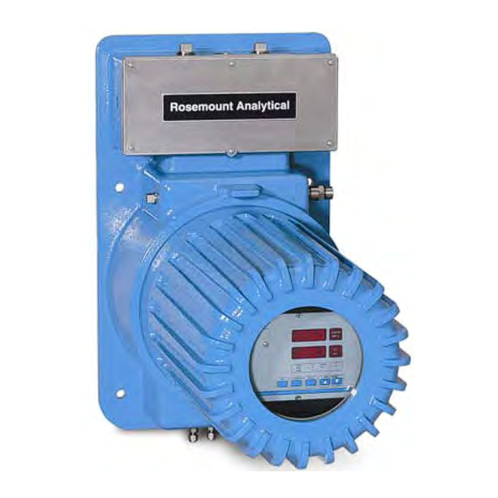
- Page 1 Instruction Manual 748441-D May 2004 Model CAT 100 Continuous Analyzer Transmitter http://www.processanalytic.com...
- Page 2 Teflon® and Viton® are registered trademarks of E. I. duPont de Nemours and Co., Inc. SNOOP® is a registered trademark of NUPRO Co. Edition 04/2002 Edition: 05/2004 Emerson Process Management Manufacturing GmbH & Co. OHG Industriestrasse 1 D-63594 Hasselroth T +49(6055) 884-0 F +49(6055) 884-209 http://www.emersonprocess.com...
-
Page 3: Table Of Contents
OPERATION .........................3-1 Startup Procedure .........................3-1 Touchpad..........................3-1 a. Overview .........................3-1 b. Elements .........................3-1 c. Actuator Tool........................3-2 d. Operation ........................3-2 e. Functions.........................3-3 FUNCTION Touchpad ....................3-4 g. ENTER Touchpad ......................3-5 h. INPUT-CONTROL Touchpads..................3-5 Rosemount Analytical Inc. A Division of Emerson Process Management Contents... - Page 4 Communication Parameters ...................4-3 String Syntax .........................4-4 a. Status Strings........................4-5 b. Numerical Representations.....................4-6 c. Block Parity Check ......................4-6 Instruction (Receive) Syntax....................4-7 a. Instruction Listing ......................4-7 b. Response String Syntax ....................4-8 Contents Rosemount Analytical Inc. A Division of Emerson Process Management...
- Page 5 Test Points for OXS PC Board..................5-35 c. Power Supply ........................5-37 TROUBLESHOOTING ......................6-1 Error Messages ........................6-1 Troubleshooting Leaks ......................6-6 RETURN OF MATERIAL ....................7-1 Return Of Material .........................7-1 Customer Service ........................7-1 Training..........................7-1 INDEX............................8-1 Rosemount Analytical Inc. A Division of Emerson Process Management Contents...
- Page 6 BKS PCB Plug Locations..................5-33 Figure 5-23. BKS PCB Jumper Locations................5-34 Figure 5-24. OXS PCB Test Points..................5-35 Figure 5-25. OXS PCB Plug Locations ................... 5-36 Figure 5-26. Power Supply Connections................. 5-37 Contents Rosemount Analytical Inc. A Division of Emerson Process Management...
- Page 7 LIST OF DRAWINGS (Located In Rear Of Manual) 659921 Assembly Drawing, CAT 100 660198 Wiring Diagram, CAT 100 660210 Installation Drawing, CAT 100 660371 Diagram, Power Input and Ground Circuits Rosemount Analytical Inc. A Division of Emerson Process Management Contents...
- Page 8 Instruction Manual 748441-D Model CAT 100 April 2002 Contents Rosemount Analytical Inc. A Division of Emerson Process Management...
-
Page 9: Preface
Highlights an operation or maintenance procedure, practice, condition, statement, etc. If not strictly observed, could result in damage to or destruction of equipment, or loss of effectiveness. NOTE Highlights an essential operating procedure, condition or statement. Rosemount Analytical Inc. A Division of Emerson Process Management Preface... -
Page 10: Intended Use Statement
Do not operate without dome and covers secure. Ensure that all gas connections are made as la- beled and are leak free. Improper gas connections could result in explosion and death. Preface Rosemount Analytical Inc. A Division of Emerson Process Management... - Page 11 Because of the danger of introducing additional hazards, do not perform any unauthorized modifi- cation to this instrument. Return the instrument to a Rosemount Analytical Service office for service or repair to ensure that safety features are maintained. Rosemount Analytical Inc. A Division of Emerson Process Management Preface...
- Page 12 See General Precautions for Handling and Storing High Pressure Gas Cylinders, page P-5. CAUTION. HEAVY WEIGHT Use two persons or a suitable lifting device to move or carry the instrument. Preface Rosemount Analytical Inc. A Division of Emerson Process Management...
-
Page 13: General Precautions For Handling And Storing High Pressure Gas Cylinders
8. Do not place cylinders where they may become part of an electric circuit. When electric arc welding, precautions must be taken to prevent striking an arc against the cylinder. Rosemount Analytical Inc. A Division of Emerson Process Management Preface... -
Page 14: Documentation
Conforms with Electromagnetic Compatibility – Generic Emission standard and AS/NZS 4251.1 – 1994 Part 1 – Residential, commercial, and light in- dustrial. Complies with the NAMUR RECOMMENDATION, Electromagnetic Com- NAMUR patibility (EMC) issue 1998. Preface Rosemount Analytical Inc. A Division of Emerson Process Management... -
Page 15: Description And Specifications
• Fluidized Catalytic Cracking in Endothermic Furnace CO and O Monitoring of Fluidized Cata- All Applications lytic Cracking Regenerator Gas Continuous Emission Monitoring Systems • Sulfur Recovery Units (CEMS) Rosemount Analytical Inc. A Division of Emerson Process Management Description and Specifications... -
Page 16: Detector Methodologies
This signal results from the cooling and measuring methods may be used as fol- heating of the pyroelectric detector mate- lows: rial. Description and Specifications Rosemount Analytical Inc. A Division of Emerson Process Management... -
Page 17: Figure 1-1. Absorption Bands Of Sample Gas And Transmittance Of Interference Filters
3200 3400 3600 3800 4000 4200 4400 4600 4800 5000 5200 5400 5600 Wave Length (nm) Figure 1-1. Absorption Bands of Sample Gas and Transmittance of Interference Filters Rosemount Analytical Inc. A Division of Emerson Process Management Description and Specifications... -
Page 18: Figure 1-2. Opto-Pneumatic Gas Detector
Fluoride (CaF trical pulses which are processed into the corresponding analyzer output. Absorption chamber Window Flow channel with Microflow sensor Compensation chamber Figure 1-2. Opto-Pneumatic Gas Detector Description and Specifications Rosemount Analytical Inc. A Division of Emerson Process Management... -
Page 19: Figure 1-3. Overall Ndir Method
Analysis Cell (undivided) (measuring side) Filter Cell Analysis Cell (reference side) Preamplifier Pyroelectric Detector (solid-state detector) Filter Cell Gas Detector Preamplifier Chopper Blade Figure 1-3. Overall NDIR Method Rosemount Analytical Inc. A Division of Emerson Process Management Description and Specifications... -
Page 20: Paramagnetic Oxygen Method
Permanent Magnet Platinum Wire Mirror Quartz Sphere(s) Wire Loop Light Source Photo detector Amplifier Display Figure 1-4. Paramagnetic Oxygen Analysis Description and Specifications Rosemount Analytical Inc. A Division of Emerson Process Management... -
Page 21: Electrochemical Oxygen Method
Lead Wire (Anode) Lead Wire (Cathode) Anode (Lead) Resistor O-Ring Plastic Disc Plastic Disk Thermistor Acid Electrolyte Sponge Disc Cathode (Gold Film) Teflon Membrane Figure 1-5. Electrochemical Oxygen Sensor Rosemount Analytical Inc. A Division of Emerson Process Management Description and Specifications... -
Page 22: Figure 1-6. Reaction Of Galvanic Cell
O → 2PbO + 4 H + 4 e 2 Pb + 2 H Electrolyte (3) (ph 6) + 2 Pb → 2 PbO Summary reaction O Figure 1-6. Reaction of Galvanic Cell Description and Specifications Rosemount Analytical Inc. A Division of Emerson Process Management... -
Page 23: Thermal Conductivity Method
Figure 1-7. Thermal Conductivity Sensor Rosemount Analytical Inc. A Division of Emerson Process Management Description and Specifications... - Page 24 Instruction Manual 748441-D Model CAT 100 May 2004 1-10 Description and Specifications Rosemount Analytical Inc. A Division of Emerson Process Management...
-
Page 25: Specifications
0(2) - 10 V, 0(4) - 20 mA, 0(0.2) - 1 V Relay Outputs: Up to 3 “non-voltage carrying contacts”, max 30 V, 1 A, 30 W Instrument Weight ......120 to 150 lbs. (55-70 kg) Rosemount Analytical Inc. A Division of Emerson Process Management Description and Specifications 1-11... -
Page 26: Cat 100 Detector
Related to full scale, per 10 K. At constant pressure and temperature. Dependent on sensor. Related to measuring value. With optional temperature stabilization. Starting from 20° C to +5 °C or +40 °C. 1-12 Description and Specifications Rosemount Analytical Inc. A Division of Emerson Process Management... -
Page 27: Installation
2 are used for channel 2 (valve or more Calibration Standards must be pro- block 2) (see Figure 2-1). vided. These should be cylinders of gas which closely resemble the expected sample, both in Rosemount Analytical Inc. A Division of Emerson Process Management Description and Specifications... -
Page 28: Figure 2-1. Gas Connections
* Standard: Outlet = Gas outlet ; Valve block outlet is connected to internal BINOS gas inlet; Option: Valve block outlet maybe used as outlet for external sample handling (special solution: consult factory) Figure 2-1. Gas Connections Installation Rosemount Analytical Inc. A Division of Emerson Process Management... -
Page 29: Figure 2-2. Piping Diagram (Two Channel Series)
Channel 2 (option) Span gas 2 Channel 1 Sample gas Gas Sampling Pump Zero gas (option) Flow Meter Throttle and Safety Filter (option) (option) Figure 2-2. Piping Diagram (Two channel series) Rosemount Analytical Inc. A Division of Emerson Process Management Installation... -
Page 30: Figure 2-3. Cat 100 Outline And Mounting Dimensions
1.00 DIMENSIONS [25.4] [15.7] INCH 1.25 [31.8] 2.25 [57.2] Figure 2-3. CAT 100 Outline and Mounting Dimensions Installation Rosemount Analytical Inc. A Division of Emerson Process Management... -
Page 31: Gas Conditioning
• Free of aggressive constituents The maximum gas flow rate for para- which may damage the gas magnetic oxygen detectors is 1.0 l/min! paths • Temperature and pressure in ac- cordance with the specifications Rosemount Analytical Inc. A Division of Emerson Process Management Installation... -
Page 32: Installation
Limitations Vent Lines See Specification, Section 1-4 (page 1- Connect all vent lines (these are specified 11). on the Application Data Sheet) to an ap- Installation Rosemount Analytical Inc. A Division of Emerson Process Management... -
Page 33: Electrical Connections
Bottom 16 (C-wht/yel) mA return (Gnd) Bottom 17 (C-wht/grn) mA return (Gnd) Bottom 18 (C-wht/blu) mA return (Gnd) Bottom 19 (C-wht/vio) mA return (Gnd) Table 2-1. Analog Output Terminal Assignments Rosemount Analytical Inc. A Division of Emerson Process Management Installation... - Page 34 Interfering gas 2 Top 4 (D-org) Interfering gas 2 Top 5 (D-yel) Interfering gas 3 Top 6 (D-grn) Interfering gas 3 (Gnd) Table 2-4. Optional Analog Inputs for TCD Cross Compensation Installation Rosemount Analytical Inc. A Division of Emerson Process Management...
- Page 35 This includes all wirings. Maximum power requirements will be 180 NOTE watts, with most applications requiring The optional case heater may increase less than this amount. power requirements to 380 watts. Rosemount Analytical Inc. A Division of Emerson Process Management Installation...
-
Page 36: Figure 2-4. Increased Safety Junction Box Terminals
If Foundation Fieldbus is selected then an- other terminal strip will be located between the power connection and the connector for the analog/digital/serial inputs and outputs (consult factory for further information). 2-10 Installation Rosemount Analytical Inc. A Division of Emerson Process Management... -
Page 37: Analytical Leak Check
Supply air or inert gas such as nitrogen, at 10 psig (689 mbar), to the analyzer CAT 100 Analyzer Inlet Outlet Flow Meter 10 psig (690mbar) Gas Outlet Figure 2-5. Leak check - Flow Indicator Method Rosemount Analytical Inc. A Division of Emerson Process Management Installation 2-11... -
Page 38: Manometer Method
For analyzers with parallel gas paths, the leak check must be performed for each gas path separately. 2-12 Installation Rosemount Analytical Inc. A Division of Emerson Process Management... -
Page 39: Operation
The battery maintains the memory for pro- grammed parameters when the analyzer is shut off. IR Entry IR Outlet Figure 3-1. CAT 100 Touch pad Rosemount Analytical Inc. A Division of Emerson Process Management Operation... -
Page 40: Actuator Tool
CAUTION. Do not touch the glass window with the actuator tool to avoid scratching the window. Figure 3-3. Storing The Actuator Tool Operation Rosemount Analytical Inc. A Division of Emerson Process Management... -
Page 41: Functions
4-digit LED displays. 300ppm para. SPAN SAMPLE SPAN ZERO PUMP SWITCH CTRL. FUNCTION ENTER INPUT CONTROL (channel labels will vary depending on configuration) Figure 3-5. CAT 100 Analyzer Touch pad Function Identification Rosemount Analytical Inc. A Division of Emerson Process Management Operation... -
Page 42: Function Touchpad
Figure 3-6. CAT 100 Touch pad Functions Only with combination of digital outputs and external solenoid valves, and if Auto = 1. Only with optional RS 232 C/ RS 485 Serial Interface. Operation Rosemount Analytical Inc. A Division of Emerson Process Management... -
Page 43: Enter Touchpad
The password has been set to the possible entry error. value “1” at the factory. We would recommend to change the password immediately after start-up for safety reasons. Rosemount Analytical Inc. A Division of Emerson Process Management Operation... -
Page 44: Figure 3-7. Analyzer Operating Function Matrix
Instruction Manual 748441-D Model CAT100 April 2002 Optional Figure 3-7. Analyzer Operating Function Matrix Operation Rosemount Analytical Inc. A Division of Emerson Process Management... -
Page 45: Entry Of System Parameters
Pure test gases are required for this Use the INPUT-CONTROL pads to operation. Once cross-compensation change the value and then activate corrections have been determined, ENTER. span adjustments may be performed using test gas mixtures. Rosemount Analytical Inc. A Division of Emerson Process Management Operation... -
Page 46: Hold
Entry of 0: The outputs remain unlocked Entry of 0: Tolerance check is deacti- vated Operation Rosemount Analytical Inc. A Division of Emerson Process Management... -
Page 47: Display Off
0.2-1 V) / 4-20 mA Use the INPUT-CONTROL pads to change the value and then activate Use the INPUT-CONTROL pads to ENTER. change the value and then activate ENTER. Rosemount Analytical Inc. A Division of Emerson Process Management Operation... -
Page 48: Response Time
ENTER. If the analyzer is equipped with a sec- ond channel, the offset for the second channel is also presented for adjust- ment. 3-10 Operation Rosemount Analytical Inc. A Division of Emerson Process Management... -
Page 49: Program Version
See Section 5-5a, page 5-29. Program Version This function displays the installed software version number. This number is also displayed when the analyzer is switched on. Rosemount Analytical Inc. A Division of Emerson Process Management Operation 3-11... -
Page 50: Calibration
“calibration” correct pressure must be entered output is activated. before performing the calibration, if it is desired to have pressure correc- tion (see Section 3-3a, page 3-7)! 3-12 Operation Rosemount Analytical Inc. A Division of Emerson Process Management... -
Page 51: Manual Calibration
The display will now show: If the actual and nominal values dis- agree, activate the ENTER pad and the display will show: (The actual concentration level) (The actual measuring value) Rosemount Analytical Inc. A Division of Emerson Process Management Operation 3-13... - Page 52 To leave the calibration mode, activate FUNCTION. (The actual measuring value) If the actual and nominal values agree, span calibration is not necessary and the next function can be selected using the FUNCTION pad. 3-14 Operation Rosemount Analytical Inc. A Division of Emerson Process Management...
-
Page 53: Automatic Calibration (Option)
ENTER. val entered referenced to the time of The display will now show: entry of the interval. Rosemount Analytical Inc. A Division of Emerson Process Management Operation 3-15... -
Page 54: Concentration Limits
Use the INPUT-CONTROL pads to set the lower limit for channel 1. Then activate the ENTER pad and the following will appear: 3-16 Operation Rosemount Analytical Inc. A Division of Emerson Process Management... -
Page 55: Measurement
Temporary flushing with Channel 1 concentration nitrogen (N ) for less than one hour (ana- Channel 2 concentration lyzer zeroing) will have no effect on the (if installed) sensitivity or stability. Rosemount Analytical Inc. A Division of Emerson Process Management Operation 3-17... -
Page 56: Shut Down
• Admit zeroing gas to the respective gas inlet fitting. • Switch on the optional gas pump. • Set the flow rate to an allowable rate. 3-18 Operation Rosemount Analytical Inc. A Division of Emerson Process Management... -
Page 57: Temperature Stabilization (Option)
The ramp rate of the tempera- ture controller is 20 °C/hr so adjust warm up time according to the ambient temperature and the controller set point. Rosemount Analytical Inc. A Division of Emerson Process Management Operation 3-19... -
Page 58: Controller Settings
Af- ter carefully removing the controller from the case, locate the DIP switch and set the switches according to the following: 3-20 Operation Rosemount Analytical Inc. A Division of Emerson Process Management... - Page 59 CYCL = 0007 Cycle Time = 7 Seconds ENTER (CYCL timE)-MAX/MIN-ENTER dPnG = 0004 Damping Factor = 4 ENTER-MAX-ENTER rANP = dSbL Ramp and Soak = Disable MENU (rANP SoAC)-ENTER-MAX-ENTER Rosemount Analytical Inc. A Division of Emerson Process Management Operation 3-21...
- Page 60 Instruction Manual 748441-D Model CAT100 April 2002 3-22 Operation Rosemount Analytical Inc. A Division of Emerson Process Management...
-
Page 61: Serial Interface Option
If the 600 and 4800 baud. syntax of the transmitted string is correct, the analyzer will transmit a response string to the An echo-mode may also be activated. Rosemount Analytical Inc. A Division of Emerson Process Management Serial Interface Option... -
Page 62: Protocols
Configuration for either 2-wire or 4-wire operation is selected from LB1 on PCB SIP485. Connect pins 1-2 for 2-wire op- eration or pins 2-3 for 4-wire operation. Serial Interface Option Rosemount Analytical Inc. A Division of Emerson Process Management... -
Page 63: Rs 232
All entries are made us the INPUT- 0 = OFF CONTROL pads and the ENTER pad. 1 = ON Message-block par- ity check: 0 = OFF 1 = ON Rosemount Analytical Inc. A Division of Emerson Process Management Serial Interface Option... -
Page 64: String Syntax
If a received instruction of the strings, and will result in transmission of code should be other than three digits in a corresponding status string. length or contain non-numerical ASCII charac- Serial Interface Option Rosemount Analytical Inc. A Division of Emerson Process Management... -
Page 65: Status Strings
Automatic calibration mode off $ID;xxx;S116;LPB<CR> Parameter outside defined range $ID;xxx;S117;LPB<CR> Pre-Flushing period is running Where: xxx: Instruction code Device ID number in RS485 mode LPB: Message-length parity byte <CR>: Terminate character Rosemount Analytical Inc. A Division of Emerson Process Management Serial Interface Option... -
Page 66: Numerical Representations
Maximum of 6 digits accepted No alphabetic characters allowed The block parity check may be enabled or disabled at the analyzer (see Section 4). Analyzer output are 6-digit real numbers Serial Interface Option Rosemount Analytical Inc. A Division of Emerson Process Management... -
Page 67: Instruction (Receive) Syntax
SP failure message (possible error batt. is clearing by read out) $ID;645;0;LPB<CR> SP pressure value $ID;646;w;LPB<CR> SP solenoid valve status (w=1: Sample gas valve w=2: zero gas valve, w=4: span gas 1, w=8: span gas 2) Rosemount Analytical Inc. A Division of Emerson Process Management Serial Interface Option... -
Page 68: Response String Syntax
Spanning channel 1 + 2 Spanning channel 1 first, then channel 2 Reserved Reserved Waiting for flushing time and t90 response time c: Relay 3 Relay without power Relay active Serial Interface Option Rosemount Analytical Inc. A Division of Emerson Process Management... -
Page 69: Maintenance And Service
CAT 100 Assembly Drawing 659921 Section 2 Installation and Section 3 Op- located in the rear of this manual. eration to verify that the analyzer is being operated properly. Rosemount Analytical Inc. A Division of Emerson Process Management Maintenance and Service... -
Page 70: Component Removal
Failure to remove power can result in elec- trical shock. Base O-Ring Extender Housing O-Ring Retaining Ring Glass Window Dome Housing Figure 5-1. CAT 100 Enclosure Assembly Maintenance and Service Rosemount Analytical Inc. A Division of Emerson Process Management... -
Page 71: Analyzer Removal
Analyzer Replacement 1. Slide the analyzer onto the mounts, 5. Reverse the process for installation. being careful that the screws and washers are on the outside. Rosemount Analytical Inc. A Division of Emerson Process Management Maintenance and Service... -
Page 72: Analyzer Configuration And Adjustment
The location of these major components trochemical) and one Infrared Photome- are show in Figure 5-2 through Figure 5-5. In addition, the following major compo- nents may be present: Maintenance and Service Rosemount Analytical Inc. A Division of Emerson Process Management... -
Page 73: Figure 5-2. Analyzer Component Layout (Infrared Channel / Oxygen Measurement, Combined)
(Channel 2) (Channel 1, alt) Pressure Sen- Paramagnetic Oxygen Sensor (depending on ana- Gas Sampling Pump Front Panel Figure 5-2. Analyzer Component Layout (Infrared Channel / Oxygen Measurement, Combined) Rosemount Analytical Inc. A Division of Emerson Process Management Maintenance and Service... -
Page 74: Figure 5-3. Analyzer Component Layout (1 Channel Oxygen Measurement, Electrochemical)
Digital Inputs (option) (Channel 1) Electrochemical Oxygen Sensor with circuit board Pressure Sen- Gas Sampling Pump Front Panel Figure 5-3. Analyzer Component Layout (1 Channel Oxygen Measurement, Electrochemical) Maintenance and Service Rosemount Analytical Inc. A Division of Emerson Process Management... -
Page 75: Figure 5-4. Analyzer Component Layout (Paramagnetic Oxygen Measurement / Thermal Conductivity, Combined)
(depending on ana- Pressure Sen- Paramagnetic Oxy- gen Detector (depending on ana- Gas Sampling Pump Front Panel Figure 5-4. Analyzer Component Layout (Paramagnetic Oxygen Measurement / Thermal Conductivity, Combined) Rosemount Analytical Inc. A Division of Emerson Process Management Maintenance and Service... - Page 76 (Channel 2) (Channel 2, Pressure Sen- Thermal Conductiv- ity Detector (depending on ana- Gas Sampling Pump Front Panel Figure 5-5. Analyzer Component Layout (Infrared Channel / Thermal Conductivity, Combined) Maintenance and Service Rosemount Analytical Inc. A Division of Emerson Process Management...
-
Page 77: Photometer Assembly
Both the window of the adapter cell and the en- chopper housing and the motor encapsu- trance window of the filter cell. Rosemount Analytical Inc. A Division of Emerson Process Management Maintenance and Service... -
Page 78: Figure 5-6. Photometer Assembly With Pyroelectrical Detector
Clamping Collar (analysis cells 1-7 mm) Clamp (analysis cells 50-200 mm) Light Source Mounting Screws Mounting Screws for Analysis Cells / Adapter Cells Temperature Sensor Figure 5-6. Photometer Assembly with Pyroelectrical Detector 5-10 Maintenance and Service Rosemount Analytical Inc. A Division of Emerson Process Management... -
Page 79: Figure 5-7. Photometer Assembly With Gas Detector
Cell Low Measuring Range Combined With Electrochemical O Measurement Absorber Absorber Gas Detector Holding Analysis Cell Preamplifier Filter Device Cell Figure 5-7. Photometer Assembly with Gas Detector Rosemount Analytical Inc. A Division of Emerson Process Management Maintenance and Service 5-11... -
Page 80: Analyzer Rear Panel
14. Solenoid valve sample gas inlet. (option) 15. Solenoid valve zero gas inlet. (option) 16. 24 VDC input. 17. Foundation Fieldbus. (option) Figure 5-8. Analyzer Rear Panel Layout 5-12 Maintenance and Service Rosemount Analytical Inc. A Division of Emerson Process Management... -
Page 81: Figure 5-9. Pin Assignments (View Looking At Rear Panel)
Interfering gas 2 Flange = Shield Not used Interfering gas 3 (Gnd) Interfering gas 3 Not used Not used Figure 5-9. Pin Assignments (View Looking At Rear Panel) Rosemount Analytical Inc. A Division of Emerson Process Management Maintenance and Service 5-13... -
Page 82: Thermal Conductivity Response Time
Al- 5-10, page 5-15). This means that the in- len-head screws, and replace the strument is supplied as standard set for a instrument top cover. 5-14 Maintenance and Service Rosemount Analytical Inc. A Division of Emerson Process Management... -
Page 83: Figure 5-10. Tc Sensor Short Response Time Setting (Standard)
Instruction Manual 748441-D Model CAT100 April 2002 Figure 5-10. TC Sensor Short Response Time Setting (Standard) Figure 5-11. TC Sensor Long Response Time Setting Rosemount Analytical Inc. A Division of Emerson Process Management Maintenance and Service 5-15... -
Page 84: Maintenance
5. Clean and inspect all components as depending upon experience, usage and necessary. site conditions. 6. Re-assemble the analyzer front panel and cover in the reverse order. 5-16 Maintenance and Service Rosemount Analytical Inc. A Division of Emerson Process Management... -
Page 85: Cleaning And Replacement Of Photometric Components
4) Zero-level adjustment baffle (not on sealed version) 5) Light source mounting screw Figure 5-12. Analyzer Photometer Assembly ( 2 Channel Infrared Analyzer, Viewed From Front Panel Side) Rosemount Analytical Inc. A Division of Emerson Process Management Maintenance and Service 5-17... -
Page 86: Light Source Replacement
6. Remove the mounting flange from the light source and position it on the new 12. Perform the physical zeroing proce- light source. dure in Section 5-4i, page 5-20. 5-18 Maintenance and Service Rosemount Analytical Inc. A Division of Emerson Process Management... -
Page 87: Removal Of Analysis Cells
1) Filter cell with signal detector assembly 2) Clamp with clamping collar 3) Clamp 4) Mounting screws for analysis cells of 50 – 200 mm length Figure 5-13. Photometer Assembly Rosemount Analytical Inc. A Division of Emerson Process Management Maintenance and Service 5-19... -
Page 88: Cleaning Of Analysis Cells And Windows
2. Position the cell body in place and digital voltmeter (DVM) with a range of 2 fasten using the two mounting screws VDC and a 3 mm hexagon wrench. 5-20 Maintenance and Service Rosemount Analytical Inc. A Division of Emerson Process Management... -
Page 89: Replacement Of Electrochemical Oxygen Sensor
(Figure 5-13, item 3) respectively for channel 1 or channel 2. • About 900,000 hours for a sensor with a response time of about 12 s Rosemount Analytical Inc. A Division of Emerson Process Management Maintenance and Service 5-21... -
Page 90: Check Of The Sensor
(N ) for less than one hour (analyzer zeroing) will have no effect on the sensitivity or stability. Figure 5-14. OXS PCB Measuring Points 5-22 Maintenance and Service Rosemount Analytical Inc. A Division of Emerson Process Management... -
Page 91: Removal Of The Sensor
5. Unscrew both allen screws shown in Figure 5-15, page 5-23. Gas connections Allen screw Allen screw Front Panel Figure 5-15. Oxygen Sensor without Infrared Channel Rosemount Analytical Inc. A Division of Emerson Process Management Maintenance and Service 5-23... -
Page 92: Figure 5-16. Oxs Pcb Connector P2
Sensor Potentiometer R4 Fastening screw OXS PCB Gas connections Sensor Fitting Tie Wrap Sensor nameplate Fastening screw Figure 5-17. Oxygen Sensor Support (Oxygen Measurement Without Infrared Channel) 5-24 Maintenance and Service Rosemount Analytical Inc. A Division of Emerson Process Management... -
Page 93: Figure 5-18. Oxygen Sensor With Infrared Channel
25) and remove the fitting complete tion 5-4b, page 5-16) with the sensor. Gas connections Fastening screws Fitting Front Panel Figure 5-18. Oxygen Sensor with Infrared Channel Rosemount Analytical Inc. A Division of Emerson Process Management Maintenance and Service 5-25... - Page 94 Sections 2-3 (page 2-11) and 6-2 (page 5-6). 4. Insert the complete support (Figure 5-18, page 5-25) into the analyzer and attach with the two allen screws (see Figure 5-15, page 5-23). 5-26 Maintenance and Service Rosemount Analytical Inc. A Division of Emerson Process Management...
-
Page 95: Basic Calibration For The Oxygen Sensor
Under normal use, the dia- phragm should be replaced every six ment frequency. months. Rosemount Analytical Inc. A Division of Emerson Process Management Maintenance and Service 5-27... -
Page 96: Replacing The Eprom
(see Section 3-4, page 3-12) must be performed after an EPROM re- Front Panel placement. Figure 5-20. BKS PCB Location of EPROM and Battery Buffer Jumper (J7) 5-28 Maintenance and Service Rosemount Analytical Inc. A Division of Emerson Process Management... -
Page 97: Analyzer Service
≤ ±10 mV)! more than 10 mV (U ref+ ref- If the difference is larger, replace the BKS Front Panel PCB. Figure 5-21. BKS PCB Test Points Rosemount Analytical Inc. A Division of Emerson Process Management Maintenance and Service 5-29... - Page 98 (replace sensor) BKS PCB faulty (replace BKS) Possible reasons (electrochemical oxy- gen measurement): Temperature sensor not connected OXS PCB faulty (replace OXS) BKS PCB faulty (replace BKS) 5-30 Maintenance and Service Rosemount Analytical Inc. A Division of Emerson Process Management...
- Page 99 500 mV DC (± 50 mV) Failure: No signal or incorrect measuring values Possible rea- Oxygen sensor not con- sons: nected Oxygen sensor faulty (replace sensor) BKS PCB faulty (replace BKS) Rosemount Analytical Inc. A Division of Emerson Process Management Maintenance and Service 5-31...
- Page 100 Failure: No signal or incorrect measuring values Possible rea- Detector sensor not con- sons: nected Detector sensor faulty (replace detector) BKS PCB faulty (replace BKS) 5-32 Maintenance and Service Rosemount Analytical Inc. A Division of Emerson Process Management...
-
Page 101: Figure 5-22. Bks Pcb Plug Locations
Chopper X3 (4/5) Light source channel 2 Oxygen sensor IR detector channel 2 Temperature sensor (chopper) Light barrier (chopper) Front Panel Figure 5-22. BKS PCB Plug Locations Rosemount Analytical Inc. A Division of Emerson Process Management Maintenance and Service 5-33... -
Page 102: Figure 5-23. Bks Pcb Jumper Locations
A/D conversion – Start channel 1 A/D conversion – Start channel 2 (open for 1 channel analyzer) Watchdog signal Buffer battery Front Panel Figure 5-23. BKS PCB Jumper Locations 5-34 Maintenance and Service Rosemount Analytical Inc. A Division of Emerson Process Management... -
Page 103: Test Points For Oxs Pc Board
OXS PCB OXS PCB not connected or faulty Oxygen sensor faulty or consumed BKS PCB faulty (replace BKS) Figure 5-24. OXS PCB Test Points Rosemount Analytical Inc. A Division of Emerson Process Management Maintenance and Service 5-35... -
Page 104: Figure 5-25. Oxs Pcb Plug Locations
PCB, X5 (sensor signal) Cable P1, 2 pin connector BKS PCB, X7 (tempera- ture sensor (not used in combina- tion with infrared measurement) Figure 5-25. OXS PCB Plug Locations 5-36 Maintenance and Service Rosemount Analytical Inc. A Division of Emerson Process Management... -
Page 105: Power Supply
No voltage or incor- essary to service the power supply. rect voltage Possible rea- Faulty power supply sons: (replace) EMI Board Fuses Neutral POWER Figure 5-26. Power Supply Connections Rosemount Analytical Inc. A Division of Emerson Process Management Maintenance and Service 5-37... - Page 106 Instruction Manual 748441-D Model CAT100 April 2002 5-38 Maintenance and Service Rosemount Analytical Inc. A Division of Emerson Process Management...
-
Page 107: Troubleshooting
Check Plug 9, pin 2 on BKS PCB. A/S Conversion End 4. IR Channel chopper drive Signal absent. Check connection X2 on BKS PCB. inoperative. 5. Internal 6 VDC supply absent. Check X14 on BKS PCB. Rosemount Analytical Inc. A Division of Emerson Process Management Troubleshooting... - Page 108 Channel 2 Measuring value more than 10% over full scale range. 1. Timeout for serial interface XON character absent. Timeout > 60 s. XON. Troubleshooting Rosemount Analytical Inc. A Division of Emerson Process Management...
- Page 109 6. IR Channel light source not Light source is cold: connected or faulty. For dual infrared channel analyzer, exchange the two light sources. Replace the suspected light source. See Section 5-4d, page 5-18. Rosemount Analytical Inc. A Division of Emerson Process Management Troubleshooting...
- Page 110 16. Temperature below the dew condensation. Maintain all temperatures at values at point in the gas paths. least 10 °C above the dew point of the sample gas. Troubleshooting Rosemount Analytical Inc. A Division of Emerson Process Management...
- Page 111 Check the valve face on the solenoid defective. valves and change if necessary. Check gas lines including filters for 6. Contamination in the gas contamination. lines. Clean gas lines and change filter elements. Rosemount Analytical Inc. A Division of Emerson Process Management Troubleshooting...
-
Page 112: Troubleshooting Leaks
SNOOP. For positive assur- ance that system is leak free, perform one of the tests in Section 2-3, page 2-11. Troubleshooting Rosemount Analytical Inc. A Division of Emerson Process Management... -
Page 113: Return Of Material
Department at: Return Authorization, prepaid, to: EMERSON PROCESS MANAGEMENT Emerson Process Management Customer Service Center Process Analytic Division USA: +1(800)433-6076 Customer Service Center EU: +49(6055)884-0 Fax: -209 USA: +1(800)433-6076 Rosemount Analytical Inc. A Division of Emerson Process Management Return of Material... - Page 114 Instruction Manual 748441-D Model CAT100 April 2002 Return of Material Rosemount Analytical Inc. A Division of Emerson Process Management...
-
Page 115: Index
3-8 unlock, 3-8 Omega Engineering model CN77322 controller settings, 3-20 dewpoint of the sample gas, 2-5 optical bench, 1-2 dwell time for calibration gas optional pressure sensor, 3-7 flow, 3-9 Rosemount Analytical Inc. A Division of Emerson Process Management Index... - Page 116 3-8 Return Authorization, 7-1 Touchpad, 3-1 reversible detuning of sensitivity, 3-17 true test gas setpoint value, 3-14 Sample Conditioning Plate Option, 2-1 warm-up time, 3-1 Sample Handling Plate, 2-2, 2-5 Index Rosemount Analytical Inc. A Division of Emerson Process Management...
- Page 121 WARRANTY Goods and part(s) (excluding consumables) manufactured by Seller are warranted to be free from defects in workmanship and material under normal use and service for a period of twelve (12) months from the date of shipment by Seller. Consumables, glass electrodes, membranes, liquid junctions, electrolyte, o-rings, etc., are warranted to be free from defects in workmanship and ma- terial under normal use and service for a period of ninety (90) days from date of shipment by Seller.
- Page 122 Instruction Manual 748441-D Model CAT 100 April 2002 Emerson Process Management Rosemount Analytical Inc. Fisher-Rosemount GmbH & Co. Process Analytic Division Industriestrasse 1 1201 N. Main St. 63594 Hasselroth Orrville, OH 44667-0901 Germany T (330) 682-9010 Phone: 49-6055-884 0 F (330) 684-4434 Fax: 49-6055-884209 E-mail: gas.csc@emersonprocess.com...
Need help?
Do you have a question about the Rosemount Analytical CAT 100 and is the answer not in the manual?
Questions and answers