
Related Manuals for Emerson Clarity II


Summary of Contents for Emerson Clarity II
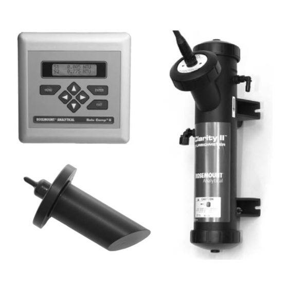
- Page 1 Instruction Manual PN 51-T1055/rev.I February 2006 Clarity II™ Turbidimeter Turbidity Measurement System...
- Page 2 This product is not intended for use in the light industrial, residential or commercial environments per the instrument’s certification to EN50081-2. Emerson Process Management Rosemount Analytical Inc. 2400 Barranca Parkway Irvine, CA 92606 USA Tel: (949) 757-8500 Fax: (949) 474-7250 http://www.raihome.com...
- Page 3 QUICK START GUIDE FOR CLARITY II TURBIDIMETER 1. Refer to Section 2.0 for installation instructions. 2. The sensor cable is pre-wired to a plug that inserts into a receiving socket in the analyzer. The cable also passes through a strain relief fitting. To install the cable…...
- Page 4 4. Once connections are secured and verified, apply power to the analyzer. 5. When the analyzer is powered up for the first time Quick Start screens appear. Using Quick Start is easy. a. A blinking field shows the position of the cursor. b.
- Page 6 About This Document This manual contains instructions for installation and operation of the Clarity II Model T1055 Turbidimeter. The following list provides notes concerning all revisions of this document. Rev. Level Date Notes 5/04 This is the CD-launch version containing only installation information.
-
Page 7: Table Of Contents
MODEL CLARITY II TABLE OF CONTENTS MODEL CLARITY II TURBIDIMETER TABLE OF CONTENTS Section Title Page DESCRIPTION AND SPECIFICATIONS ................Features and Applications ...................... Specifications ......................... INSTALLATION........................Unpacking and Inspection ...................... Installation — Analyzer......................Installation — Flow Chamber and Debubbler................. - Page 8 MODEL CLARITY II TABLE OF CONTENTS LIST OF FIGURES Number Title Page Panel Mount Installation ................... Pipe Mount Installation ..................... Surface Mount Installation ..................Opening the Supporting Clamps ................Debubbler and Flow Chamber ................. Sensor ........................Sampling for Turbidity....................Removing the Knockouts ..................
-
Page 9: Description And Specifications
Because it measures optional alarm board with three relays is also avail- turbidity as high as 200 NTU, Clarity II is also suitable able. Alarms are fully programmable for high/low logic for most raw waters. The Clarity II turbidimeter can be and dead band. -
Page 10: Specifications
MODEL CLARITY II SECTION 1.0 DESCRIPTION AND SPECIFICATIONS 1.2 SPECIFICATIONS — ANALYZER Field wiring terminals: removable terminal blocks for power, analog outputs, and sensors Enclosure: ABS (panel mount), polycarbonate (pipe/wall mount); NEMA 4X/CSA 4 (IP65) Dimensions: Panel mount version: 6.10 X 6.10 X 3.72 in (155 X 155 X SPECIFICATIONS —... -
Page 11: Installation
INSTALLATION 2.1 UNPACKING AND INSPECTION The Clarity II Turbidimeter is a complete system for the determination of turbidity in drinking water. The system consists of the analyzer, sensor(s), cable(s), and flow chamber/debubbler(s). Consult the table to verify that you have received the parts for the option you ordered. -
Page 12: Panel Mount Installation
MODEL CLARITY II SECTION 2.0 INSTALLATION 2.2.2 Panel Mounting. MILLIMETER INCH FIGURE 2-1. Panel Mount Installation Access to the wiring terminals is through the rear cover. Four screws hold the cover in place. -
Page 13: Pipe Mount Installation
MODEL CLARITY II SECTION 2.0 INSTALLATION 2.2.3 Pipe Mounting. MILLIMETER INCH FIGURE 2-2. Pipe Mount Installation The front panel is hinged at the bottom. The panel swings down for access to the wiring terminals. -
Page 14: Surface Mount Installation
MODEL CLARITY II SECTION 2.0 INSTALLATION 2.2.4 Surface Mounting. MILLIMETER INCH FIGURE 2-3. Surface Mount Installation The front panel is hinged at the bottom. The panel swings down for access to the wiring terminals. -
Page 15: Installation - Flow Chamber And Debubbler
MODEL CLARITY II SECTION 2.0 INSTALLATION 2.3 INSTALLATION — DEBUBBLER ASSEMBLY See Figure 2-4 for installation. Connect the sample line to the inlet fitting. The fitting accepts 1/4-inch OD tubing. See Section 2.6 for recom- mended installation of the sample port. -
Page 16: Debubbler And Flow Chamber
MODEL CLARITY II SECTION 2.0 INSTALLATION INCH MILLIMETER FIGURE 2-4. Debubbler and Flow Chamber... -
Page 17: Installation - Sensor
MODEL CLARITY II SECTION 2.0 INSTALLATION 2.4 INSTALLATION — SENSOR Unscrew the nut on the side of the debubbler. Insert the sensor in the mouth of the measuring chamber. Be sure the pin on the debubbler lines up with the hole in the sensor. Replace the nut. Remove the protective cap from the sensor and screw the cable onto the receptacle. -
Page 18: Wiring
MODEL CLARITY II SECTION 3.0 WIRING SECTION 3.0. WIRING 3.1 PREPARING CONDUIT OPENINGS The analyzer enclosure has five conduit openings. Two are open and three are knockouts. Conduit openings accept 1/2-inch conduit fittings or PG 13.5 cable glands. To keep the case watertight, block unused openings with NEMA 4X or IP65 conduit plugs. - Page 19 MODEL CLARITY II SECTION 3.0 WIRING 3.2.2 Sensor The sensor cable is pre-wired to a plug that inserts into a receiving socket in the analyzer. See Figures 3-2 and 3-3 for the locations of the sockets. If you are using a single input analyzer, be sure to plug the sensor into the SENSOR 1 receptacle.
-
Page 20: Non-Incendive Installation Control Drawings
MODEL CLARITY II SECTION 3.0 WIRING C 1400311... - Page 21 MODEL CLARITY II SECTION 3.0 WIRING C 1400312...
- Page 22 MODEL CLARITY II SECTION 3.0 WIRING C 1400313...
- Page 23 MODEL CLARITY II SECTION 3.0 WIRING C 1400314...
-
Page 24: Display And Operation
SECTION 4.0 DISPLAY AND OPERATION 4.1. DISPLAY The Solu Comp II analyzer provided with the Clarity II has a two-line display. The display can be customized to meet user requirements (see Section 5.11). Figure 4-1 shows some of the displays avail- able during normal operation. -
Page 25: Programming And Calibrating The Solu Comp Ii - Tutorial
MODEL CLARITY II SECTION 4.0 DISPLAY AND OPERATION 4.3 PROGRAMMING AND CALIBRATING THE SOLU COMP II — TUTORIAL Setting up and calibrating the Solu Comp II analyzer is easy. The following tutorial describes how to move around in the programming menus. For prac- tice, the tutorial also describes how to assign turbidity values to the 4 and 20 mA outputs for sensor 1. -
Page 26: Security
MODEL CLARITY II SECTION 4.0 DISPLAY AND OPERATION 4.4 SECURITY 4.4.1 How the Security Code Works Use the security code to prevent accidental or unwanted changes to program settings, displays, and calibration. 1. If a security code has been programmed, pressing MENU causes the Enter Security security screen to appear. -
Page 27: Programming The Analyzer
MODEL CLARITY II SECTION 5.0 PROGRAMMING THE ANALYZER SECTION 5.0 PROGRAMMING THE ANALYZER 5.1 GENERAL This section describes how to do the following: 1. configure and assign values to the current outputs 2. configure and assign setpoints to the alarm relays 3. -
Page 28: Sensor 1
MODEL CLARITY II SECTION 5.0 PROGRAMMING THE ANALYZER TABLE 5-1. DEFAULT SETTINGS 1. OUTPUT CONFIGURATION assigned to dampening mA range section output 1 sensor 1 4 - 20 output 2* sensor 2 4 - 20 *Output 2 is available only with the dual input option. -
Page 29: Configuring And Ranging The Outputs
MODEL CLARITY II SECTION 5.0 PROGRAMMING THE ANALYZER 5.3 CONFIGURING AND RANGING THE OUTPUTS. 5.3.1 Purpose The analyzer is available in single or dual input versions. The single input analyzer has one current output. The dual input analyzer has two current outputs. This section describes how to configure and range the outputs. - Page 30 MODEL CLARITY II SECTION 5.0 PROGRAMMING THE ANALYZER 5.3.3. Procedure: Configure Outputs. To choose a menu item, move the cursor to the item and press ENTER. To store a number or setting, press ENTER. 1. Press MENU. The main menu screen appears. Choose Program.
-
Page 31: Configuring Alarms And Assigning Setpoints
MODEL CLARITY II SECTION 5.0 PROGRAMMING THE ANALYZER 5.4 CONFIGURING ALARMS AND ASSIGNING SETPOINTS 5.4.1 Purpose This section describes how to do the following: 1. disable all alarms, 2. assign an alarm relay to a sensor, 3. set the alarm logic to high or low, 4. - Page 32 MODEL CLARITY II SECTION 5.0 PROGRAMMING THE ANALYZER 5.4.3 Procedure: Configuring Alarms To choose a menu item, move the cursor to the item and press ENTER. To store a number or setting, press ENTER. 1. Press MENU. The main menu screen appears. Choose Program.
- Page 33 MODEL CLARITY II SECTION 5.0 PROGRAMMING THE ANALYZER 5.4.4 Procedure: Programming Alarm Setpoints To choose a menu item, move the cursor to the item and press ENTER. To store a number or setting, press ENTER. Calibrate Hold 1. Press MENU. The main menu screen appears. Choose Program.
-
Page 34: Choosing Turbidity Or Total Suspended Solids
MODEL CLARITY II SECTION 5.0 PROGRAMMING THE ANALYZER 5.5 CHOOSING TURBIDITY OR TOTAL SUSPENDED SOLIDS 5.5.1 Purpose This section describes how to do the following: 1. Configure the analyzer to display results as turbidity or total suspended solids (TSS). 2. Choose units in which results are to be displayed. - Page 35 Although ISO 7027 allows a laser, light emitting diode, or tunsten filament lamp fitted with an interference fil- ter as the light source, most instruments, including the Clarity II, use an 860 nm LED. Because ISO 7027 tur- bidimeters use a longer wavelength for the measurement, they tend to be more sensitive to larger particles than EPA 180.1 turbidimeters.
- Page 36 MODEL CLARITY II SECTION 5.0 PROGRAMMING THE ANALYZER 5.5.3 Procedure: Selecting Turbidity or TSS To choose a menu item, move the cursor to the item and press ENTER. To store a number or setting, press ENTER. 1. Press MENU. The main menu screen appears. Choose Program.
-
Page 37: Choosing Single Sensor Or Dual Sensor Input
MODEL CLARITY II SECTION 5.0 PROGRAMMING THE ANALYZER 5.6 CHOOSING SINGLE SENSOR OR DUAL SENSOR INPUT 5.6.1 Purpose The Solu Comp II accepts input from a single sensor or from two sensors. The screens in this section appear only if you purchased a dual input analyzer. This section gives you the opportunity to configure a dual sen- sor analyzer to accept a single sensor input. -
Page 38: Setting A Security Code
MODEL CLARITY II SECTION 5.0 PROGRAMMING THE ANALYZER 5.7 SETTING A SECURITY CODE 5.7.1 Purpose. This section describes how to set a security code. The security code prevents program and calibration settings from accidentally being changed. Refer to Section 4.4 for additional information. -
Page 39: Resetting Factory Default Settings
MODEL CLARITY II SECTION 5.0 PROGRAMMING THE ANALYZER 5.9 RESETTING FACTORY DEFAULT SETTINGS 5.9.1 Purpose. This section describes how to re-install factory default values. The process also clears all fault messages and returns the display to the first quick start screen. -
Page 40: Selecting A Default Screen, Language, And Screen Contrast
MODEL CLARITY II SECTION 5.0 PROGRAMMING THE ANALYZER 5.10 SELECTING A DEFAULT SCREEN, LANGUAGE, AND SCREEN CONTRAST 5.10.1 Purpose This section describes how to do the following: 1. set a default display screen The default display screen is the screen shown during normal operation. The Solu Comp II allows the user to customize the default display. - Page 41 MODEL CLARITY II SECTION 5.0 PROGRAMMING THE ANALYZER 5.10.4 Procedure: Choosing a Language Calibrate Hold 1. Press MENU. The main menu screen appears. Choose Display. D D i i s s p p l l a a y y Program Default Display 2.
-
Page 42: Calibration
MODEL CLARITY II SECTION 6.0 CALIBRATION SECTION 6.0 CALIBRATION 6.1 INTRODUCTION The calibrate menu allows the user to calibrate the turbidity sensor, to enter the equation the analyzer will use to convert turbidity to a TSS reading, and to calibrate the outputs. - Page 43 MODEL CLARITY II SECTION 6.0 CALIBRATION Refer to the table to select the appropriate size volumetric flask and pipet. A single calibration requires about 300 mL of standard. Be sure to thoroughly mix the 4000 NTU standard before withdrawing liquid from the bottle.
- Page 44 MODEL CLARITY II SECTION 6.0 CALIBRATION 10. The screen at left appears showing that the sensor dark current is being Dark cal in measured. This step takes 30 seconds. If the reading does not stabilize progress... after about 2 minutes, press ENTER. The analyzer will use the current dark reading.
-
Page 45: Calibrating Against A Commercial Standard
MODEL CLARITY II SECTION 6.0 CALIBRATION 6.3 CALIBRATING AGAINST A COMMERCIAL STANDARD 6.3.1 Purpose The turbidity sensor can also be calibrated against a commercial standard. Stable 20.0 NTU standards are avail- able from a number of sources. Calibration using a commercial standard is simple. Filtered deionized water is not required. - Page 46 MODEL CLARITY II SECTION 6.0 CALIBRATION If the dark current is too high, the screen at left appears. Be sure the sen- Bad Dark cal. sor is squarely and securely seated in the calibration cup. Press EXIT and repeat the calibration. If the dark current measurement is acceptable, the screen in step 9 appears.
-
Page 47: Calibrating The Turbidity Sensor Against A Grab Sample
MODEL CLARITY II SECTION 6.0 CALIBRATION 6.4 CALIBRATING THE TURBIDITY SENSOR AGAINST A GRAB SAMPLE 6.4.1 Purpose If desired, the turbidity sensor can be calibrated against the turbidity reading from another instrument. The ana- lyzer treats the value entered by the user as though it were the true turbidity of the sample. Therefore, grab sam- ple calibration changes the sensitivity, it does not apply an offset to the reading. - Page 48 Slope too high or Slope too low implies the turbidity measured using the referee instrument (entered in step 9) is Slope too high substantially different from the turbidity measured by the Clarity II. For Continue? additional troubleshooting information, see Section 8.3.3.
-
Page 49: Lamp Calibration
MODEL CLARITY II SECTION 6.0 CALIBRATION 6.5 LAMP CALIBRATION 6.5.1 Purpose Turbidity is a measure of the amount of light scattered by small particles suspended in a liquid. Turbidity depends on both the quantity of particles in the sample and the intensity of the light used to make the measurement. In USEPA-compliant turbidity sensors the light source is a tungsten filament lamp. -
Page 50: Using The Dry Check Standard
6.6 USING THE DRY CHECK CUP A dry check cup is available for checking the operation of the Clarity II turbidimeter. To use the dry check… 1. Calibrate the turbidimeter using one of the methods described in Section 6.2, 6.3, or 6.4. For regulatory report- ing purposes, the turbidimeter must be calibrated against user-prepared formazin standard or against a com- mercial standard acceptable to the regulatory agency. -
Page 51: Entering A Turbidity To Tss Conversion Equation
MODEL CLARITY II SECTION 6.0 CALIBRATION 6.7 ENTERING A TURBIDITY TO TSS CONVERSION EQUATION 6.7.1 Purpose The analyzer can be programmed to convert turbidity to a total suspended solids (TSS) reading. There is no fun- damental relationship between turbidity and TSS. Every process stream is unique. The user must determine the relationship between turbidity and TSS for his process. - Page 52 MODEL CLARITY II SECTION 6.0 CALIBRATION 6.7.2 Procedure 1. First, calibrate the sensor. See Section Section 6.2, 6.3, or 6.4. 2. Press the MENU key. The main menu appears. Choose Calibrate. C C a a l l i i b b r r a a t t e e...
-
Page 53: Calibrating Current Outputs
MODEL CLARITY II SECTION 6.0 CALIBRATION 6.8 CALIBRATING CURRENT OUTPUTS 6.8.1 Purpose Although the analyzer outputs are calibrated at the factory, they can be trimmed in the field to match the reading from a standard current meter. Both the low (0 or 4 mA) and the high (20 mA) outputs can be trimmed. -
Page 54: Maintenance
7.1 SOLU COMP II ANALYZER The Solu Comp II analyzer used in the Clarity II turbidimeter needs little routine maintenance. Clean the analyzer case and front panel by wiping it with a clean soft cloth dampened with water ONLY. Do not use solvents, like alcohol, that might cause a buildup of static charge. -
Page 55: Exploded View Of Solu Comp Ii (Pipe/Surface Mount Version)
MODEL CLARITY II SECTION 7.0 MAINTENANCE TABLE 7-2. Replacement Parts for Solu Comp II (Pipe/Surface Mount Version) Location in Shipping Figure 7-2 Description Weight note Screw, 6-32 x 1.38 in. — note O-ring 2-007 — 33655-00 Gasket for pipe/surface mount version 2 lb/1.0 kg... -
Page 56: Sensor
MODEL CLARITY II SECTION 7.0 MAINTENANCE 7.2 SENSOR 7.2.1 Cleaning the sensor Clean the sensor by rinsing it with water followed by wiping with a soft tissue. If water is inadequate, wash with a mild detergent solution followed by thorough rinsing with water. Do not scratch the lamp or photodiode win- dows. -
Page 57: Debubbler And Measuring Chamber
MODEL CLARITY II SECTION 7.0 MAINTENANCE 9. Place the sensor in the calibration cup and reconnect the cable. 10. Calibrate the sensor using either slope or standard calibration (Section 6.2 or 6.3). Do not use grab calibra- tion. Failure to calibrate the sensor may reduce the life of the sensor. See Sections 8.2.5 and 8.2.6. -
Page 58: List Of Replacement Parts
MODEL CLARITY II SECTION 7.0 MAINTENANCE FIGURE 7-4. Molded Debubbler Assembly 7.4 LIST OF REPLACEMENT PARTS LOCATION IN PART DESCRIPTION FIGURE 7-4 NUMBER — Replacement lamp board assembly, USEPA-compliant sensor 1-0901-004-EPA — Replacement lamp board assembly, ISO-compliant sensor 1-0901-005-ISO —... -
Page 59: Troubleshooting
8.2.1 Lamp/LED Failure The light source in a Clarity II turbidity sensor can be either a tungsten filament lamp or an LED. USEPA-compli- ant sensors use a tungsten lamp. ISO-compliant sensors use an LED. A photodiode inside the sensor continuously monitors the intensity of the light source. - Page 60 Need Cal The Clarity II sensor contains two photodiodes. One measures the intensity of the light scattered by the sample. The other measures the intensity of the lamp. Because turbidity is proportional to the intensity of light falling on the sample photodiode, any reduction of the lamp intensity will be measured as a decrease in turbidity even though the true turbidity remained constant.
-
Page 61: Troubleshooting Calibration Problems
MODEL CLARITY II SECTION 8.0 TROUBLESHOOTING 8.3 TROUBLESHOOTING CALIBRATION PROBLEMS Once the user has completed the calibration sequence, the analyzer verifies that the calibration meets certain requirements. If the calibration is valid, the analyzer displays the calibration complete screen and updates the cal- ibration. -
Page 62: Troubleshooting Other Problems
MODEL CLARITY II SECTION 8.0 TROUBLESHOOTING 8.4 TROUBLESHOOTING OTHER PROBLEMS Problem Section Readings are erratic 8.4.1 Readings drift 8.4.2 Analyzer responds too slowly to changes in turbidity 8.4.3 Flow is too low 8.4.4 Readings are lower or higher than expected 8.4.5... - Page 63 MODEL CLARITY II SECTION 8.0 TROUBLESHOOTING 8.4.3 Analyzer responds too slowly to changes in turbidity Response time is primarily a function of sample flow rate, distance between the sample point and analyzer, and the diameter of the sample tubing. Because the debubbler has a flow restrictor on the outlet to increase back pres- sure, sample flow rate is primarily determined by the inlet pressure.
-
Page 64: Information Screens
MODEL CLARITY II SECTION 8.0 TROUBLESHOOTING 8.5 INFORMATION SCREENS 8.5.1 Overview Information screens provide data that can be helpful in diagnosing measurement problems. To read the infor- mation screens, go to the main display and press . Each press will display a new information screen. Once all the information screens have been displayed, the analyzer will show warning and fault screens. - Page 65 MODEL CLARITY II SECTION 8.0 TROUBLESHOOTING 5. This screen appears only if the analyzer was configured to convert the XXXppm/NTU turbidity reading to TSS. The first line is the slope of the calibration curve. Low lim XXX.XNTU The second line is the lower limit for the turbidity measurement. A meas- ured turbidity below this value will return a negative TSS value.
-
Page 66: Return Of Material
MODEL CLARITY II SECTION 9.0 RETURN OF MATERIAL SECTION 9.0 RETURN OF MATERIAL 9.1 GENERAL. To expedite the repair and return of instruments, proper communication between the customer and the factory is important. Before returning a product for repair, call 1-949-757-8500 for a Return Materials Authorization (RMA) number. -
Page 67: Appendix
This procedure describes how to verify linearity between turbidity and TSS. 1. Collect a sample of the process liquid-you may need 10 L or more if you use the Clarity II for measuring tur- bidity. If you use a laboratory turbidimeter, you will need less volume. The Clarity II requires about 500 mL for the measurement;... - Page 68 NESS FOR PARTICULAR PURPOSE, OR ANY OTHER MATTER WITH RESPECT TO ANY OF THE GOODS OR SERVICES. RETURN OF MATERIAL Material returned for repair, whether in or out of warranty, should be shipped prepaid to: Emerson Process Management Liquid Division 2400 Barranca Parkway...
- Page 69 ON-LINE ORDERING NOW AVAILABLE ON OUR WEB SITE right now. http://www.raihome.com Specifications subject to change without notice. Credit Cards for U.S. Purchases Only. Emerson Process Management Liquid Division 2400 Barranca Parkway Irvine, CA 92606 USA Tel: (949) 757-8500 Fax: (949) 474-7250 http://www.raihome.com...
Need help?
Do you have a question about the Clarity II and is the answer not in the manual?
Questions and answers