
Related Manuals for Emerson CSI 2140


Summary of Contents for Emerson CSI 2140
- Page 1 User Guide MHM-97432, Rev 7 March 2016 ™ CSI 2140 Machinery Health Analyzer User Guide...
- Page 2 Information in this document is subject to change without notice and does not represent a commitment on the part of Emerson Process Management.
-
Page 3: Table Of Contents
Contents Contents Chapter 1 CSI 2140 Machinery Health Analyzer .................1 CSI 2140 Machinery Health Analyzer overview ................1 User Guide overview ........................1 Documentation conventions ......................1 Precautions and general maintenance ....................2 Technical Support and Customer Service ..................3 Chapter 2 Introduction to the analyzer .....................5... - Page 4 Contents Plot route data ..........................93 Run Analyze to collect data for a route measurement point ............93 4.10 View the route measurement point setup and history ..............94 4.11 Route reports ..........................96 Chapter 5 Plots ..........................99 View a full screen version of the plot .................... 99 Select an active plot ........................
- Page 5 Appendix B View and control your CSI 2140 from a PC ..............377 CSI 2140 Remote Display Viewer ....................377 Load the CSI 2140 Remote Display Viewer onto your CSI 2140 ........... 378 View and control the CSI 2140 from your PC ................379 Transfer files while using the CSI 2140 Remote Display Viewer ...........381...
- Page 6 Contents Appendix C Add channels to your CSI 2140 ..................383 Glossary ............................385 Index ..............................391 MHM-97432 Rev 7...
-
Page 7: Csi 2140 Machinery Health Analyzer
Technical Support and Customer Service CSI 2140 Machinery Health Analyzer overview The CSI 2140 Machinery Health Analyzer is a portable vibration analyzer that lets you quickly and easily collect data from rotating equipment in process plants, do an on-site analysis of the machine, and export results to the AMS Suite: Machinery Health Manager ™... -
Page 8: Precautions And General Maintenance
Charge, remove, and replace the battery pack only in a non-hazardous area. • Use only Emerson's battery packs with the CSI 2140. The analyzer will not function if a non-Emerson battery pack is used. Lithium-Ion batteries have very specific charging requirements. -
Page 9: Technical Support And Customer Service
To prevent damage to the analyzer: • Do not connect a signal larger than 0 to 24 volts into the Accel input of the CSI 2140. • Do not connect a signal larger than +/- 24 volts into the Volts / Tach input of the CSI 2140. - Page 10 Be at your computer when you call. We can serve you better when we can work through the problem together. Software Technical Support Emerson provides technical support through the following for those with an active support agreement: • Telephone assistance and communication via the Internet.
-
Page 11: Introduction To The Analyzer
CSI 2140 Four-Channel Input Adapter • Multiple inputs • CSI 2140 for use in hazardous locations Standard equipment Unpack the analyzer and compare the contents of the package to the list below. If you find a discrepancy, contact your local sales representative immediately. - Page 12 Introduction to the analyzer Note The CSI 2140 does not support cables with 25-pin connectors or cables that connect to the Volts/ Tach input from previous CSI vibration analyzers. MHM-97432 Rev 7...
-
Page 13: Front View
ALT key - Display an alternate screen, if available. Back key - Back up to the main menu in a program. (1) To comply with relevant safety certifications, the CSI 2140 labeled "ATEX/IECEx Zone 2" does not have a keypad backlight. MHM-97432 Rev 7... -
Page 14: Top View
• Do not connect a signal outside the range of +/- 24 volts into the Volts / Tach input of the CSI 2140. Turn on the analyzer for the first time You need to activate the battery pack before you can turn on the analyzer for the first time. -
Page 15: Use The Stand
Press and hold the button on the strap connector, and insert it into the connectors on the sides of the analyzer or the CSI 2140 Four-Channel Input Adapter, if attached. To release the strap, press and hold the button on the connector and then pull. -
Page 16: Battery Pack
WARNING! Use only Emerson battery packs with the CSI 2140. The analyzer will not function if a non- Emerson battery pack is used. Lithium-Ion batteries have very specific charging requirements. - Page 17 • Do not change or remove the battery pack in the CSI 2140 with the power supply connected to the analyzer. The CSI 2140 or battery pack may be damaged.
- Page 18 -4° F to 122° F ( -20° C to 50° C). WARNING! • Use only Emerson's battery packs with the CSI 2140. The analyzer will not function if a non-Emerson battery pack is used. Lithium-Ion batteries have very specific charging requirements. Emerson-supplied power supplies and chargers are designed to work with Emerson's Lithium-Ion battery pack.
- Page 19 • When charging the CSI 2140 with the battery pack or the battery pack by itself, ensure the ambient temperature where charging is occurring is 50° F to 95° F (10° C to 35° C).
- Page 20 Damage may occur to the analyzer or the battery pack. WARNING! • Use only Emerson's battery packs with the CSI 2140. The analyzer will not function if a non-Emerson battery pack is used. • Remove or change the battery pack only in a non-hazardous area.
- Page 21 • Set the LCD backlight intensity to "medium". If you use the "High" setting, Emerson recommends setting the backlight timer to 30 seconds. These options are available on the General Analyzer Setup screen. Press Home > ALT > F2 General Setup.
-
Page 22: External Csi 2140 Battery Charger
You can charge one battery pack at a time using the external CSI 2140 Battery Charger. A full recharge may take 3 hours. To power the external CSI 2140 Battery Charger, insert the power supply cord into the connector on the back of the charger. - Page 23 • Use the external CSI 2140 Battery Charger only in a non-hazardous area. This device complies with Part 15 of the FCC Rules. Operation is subject to the following...
- Page 24 Ensure the air vents on the external CSI 2140 Battery Charger are clear and uncovered. • When charging the CSI 2140 with the battery pack or the battery pack by itself, ensure the ambient temperature where charging is occurring is 50° F to 95° F (10° C to 35° C).
-
Page 25: Turn The Analyzer On Or Off
Introduction to the analyzer To remove the battery pack, lift up the battery pack to clear the two raised edges, and then slide out the battery pack. Turn the analyzer on or off You can set the number of seconds to hold the power key to shut down the analyzer. See Section 2.14.6. -
Page 26: Home Screen
Introduction to the analyzer 2.10 Home screen The Home screen appears when you turn on the analyzer by pressing the power key. Figure 2-9: Home screen An alternate screen (ALT) includes additional options. Current time and date. Default splash screen. Remaining battery pack charge. - Page 27 Introduction to the analyzer ALT1 keys Option Description Intentionally blank. Copy, delete, or move routes or jobs saved in the analyzer internal memory F2 File Utility or a memory card. Intentionally blank. F4 Set Display Units Set the default display units for the measurement values and plots. Set the communication options to connect the analyzer to AMS Machinery F5 Comm Setup Manager.
-
Page 28: Backlight
Introduction to the analyzer Option Description Intentionally blank. Intentionally blank. 2.10.1 Return to the Home screen Press the Home key on the front of the analyzer. 2.11 Backlight 2.11.1 Set the LCD backlight By default, the analyzer uses the Auto backlight mode to automatically adjust the backlight intensity based on the light in your environment. -
Page 29: Touchscreen
Introduction to the analyzer Note To comply with relevant safety certifications, the CSI 2140 labeled "ATEX/IECEx Zone 2" does not have a keypad backlight. Procedure Press the keypad backlight key to turn the light on or off. 2.12 Touchscreen The touchscreen and function keys let you access the menu options and enter text. If the touchscreen does not respond accurately, calibrate the touchscreen. - Page 30 Introduction to the analyzer Press Enter. 2.12.3 Gestures You can use gestures rather than pressing the keys to select menu options. The gestures match the arrows on the corresponding analyzer keys. You can use gestures on all screens that support the corresponding keys. Note You cannot use gestures when the analyzer displays the onscreen keyboard, or when Log is used for the plot axis.
- Page 31 Introduction to the analyzer Gestures Up arrow (swipe up) Left arrow (swipe left) Down arrow (swipe down) 2.12.4 Onscreen keyboard If the analyzer's touchscreen is enabled/unlocked, the analyzer displays an onscreen keyboard when you need to enter alphanumeric or special characters. See Section 2.12.1 for more information on locking or unlocking the touchscreen.
- Page 32 Introduction to the analyzer Figure 2-10: Examples of the onscreen keyboard Option Description View the characters you enter in the field. Tap the box to enable to disable this Show Hidden Text feature. By default, the option is disabled and only the last character you entered is visible.
-
Page 33: Menu Navigation
Introduction to the analyzer Option Description Delete all characters. CLEAR Left and right Move the cursor. You can also touch the screen to move the cursor. arrows ENTER Accept your edits and close the keyboard. You can also press the Enter key on the analyzer. -
Page 34: Settings
Introduction to the analyzer 2.13.2 Entering text If a menu option lets you enter text, an onscreen keyboard appears or the analyzer lists a set of characters on the side of the screen. Tap the touchscreen or repeatedly press the key until the desired character appears. - Page 35 Introduction to the analyzer conserve battery power. The standby timer also shuts off the keypad backlight. The standby timer is disabled when the power supply is connected to and powers the analyzer. The blue LED displays on the front of the analyzer when the analyzer is in standby. To leave standby, quickly press the power key.
- Page 36 Introduction to the analyzer Option Description Send files between the analyzer and AMS Machinery Manager. Files Send to PC can include routes, jobs, screen captures, splash screens, or summary reports. The default is Send to PC. Store as BMP on CARD Save the file as a .bmp to the SD memory card. Store as JPG on CARD Save the file as a .jpg to the SD memory card.
- Page 37 Introduction to the analyzer Procedure Press Home > ALT > F3 Set Time. Set the following options. Option Description F2 Set Local Time Enter values for the time and date. Use the arrow keys to go to the next value. F5 Date Display Format Select the format used for the date.
-
Page 38: Memory Card
Introduction to the analyzer Option Description Set the amplitude axis type. Not applicable for the Balance program. F10 Change Y Axis Type The default is Linear. Set the frequency axis type. Not applicable for the Balance program. F11 Change X Axis The default is Linear. -
Page 39: Bluetooth
Bluetooth receiver and any headphone. You can use the CSI 2130 A646 headphones with the Bluetooth functionality in the CSI 2140. You need the adapter cable from Emerson and an A2DP Bluetooth receiver available online or from an electronics store. - Page 40 Introduction to the analyzer To listen to data, open the Route or Analyze program and select the Listen To Live Data option after the connection is made. 2.16.1 Enable or disable the Bluetooth radio in the analyzer If your analyzer is configured for Bluetooth, you can enable or disable the internal radio. After you enable the analyzer's Bluetooth radio, the analyzer searches for nearby Bluetooth devices that you can pair.
- Page 41 Introduction to the analyzer If more than one device is listed, use the up and down arrow keys to select a Bluetooth device. (Optional) Press F8 Device Info to view information about the device, including device alias (if you renamed the device), device name, supported protocols, status and device address.
-
Page 42: Utilities
Introduction to the analyzer If more than one device is listed, use the up and down arrow keys to select a Bluetooth device at the bottom of the screen. Press F3 Rename Device and enter up to 16 characters to change the name of the device. - Page 43 Introduction to the analyzer File types and extensions Note The CSI 2140 uses different file extensions than the CSI 2130. File extension File type .ANJ Analyze or Advanced Analyze job .BJB Balance job .ODJ ODS/Modal job .RDA Route Data File (created after a route is activated) .RDF...
- Page 44 Introduction to the analyzer A checkmark appears next to the file. Press F7 Delete. Press Enter to delete the file, or press Back to cancel. Move a route or a job file to a memory card or internal memory Insert a memory card into the analyzer. Press Home >...
- Page 45 Introduction to the analyzer Note This operation may take several hours. Procedure Press Home > ALT > F4 Memory Utility > F3 Clean Disk. Clear the internal settings You can clear the internal settings of the analyzer that are stored in permanent memory. The default settings are loaded the next time you turn on the analyzer.
-
Page 46: Clean The Analyzer
Accel. Each side has a connector labeled "To CSI 2140". Use the appropriate Interface cable to connect the CSI 2140 Four-Channel Input Adapter to the CSI 2140. The Accel side has a 5-pin connector. The Volts side has an 8-pin connector. -
Page 47: Multiple Inputs
Balance program. For the Balance program, you must enable the mux option to use the CSI 2140 Four-Channel Input Adapter. To access the other connectors, turn the adapter over and connect to the CSI 2140 using the appropriate Interface cable. -
Page 48: Csi 2140 For Use In Hazardous Locations
CSI 2140 for use in hazardous locations Be aware of the appropriate approvals before operating the CSI 2140 in hazardous locations. Each CSI 2140 has a label attached to the back of the unit that designates with approval markings the approved locations for use: Label... - Page 49 • CSI 430 SpeedVue Sensor may not be compatible with the CSI 2140 labeled "ATEX/IECEx Zone 2." The CSI 430 is not permitted in hazardous areas; and it may not function with the ATEX- certified CSI 2140 even in a safe area.
- Page 50 Introduction to the analyzer MHM-97432 Rev 7...
-
Page 51: Transfer Files With Csi 2140
Transfer files with CSI 2140 Transfer files with CSI 2140 Topics covered in this chapter: • AMS Machinery Manager Data Transfer • AMS Machinery Manager Standalone Data Transfer application • Communication setup • Routes and jobs • Analyzer firmware and programs •... -
Page 52: Communication Setup
3.3.1 Compatible versions of AMS Machinery Manager You must use AMS Machinery Manager version 5.61 or newer with the CSI 2140. The analyzer uses a different format for routes, which is not compatible with previous versions of AMS Machinery Manager. - Page 53 Transfer files with CSI 2140 Press Enter. Press Enter to return to the Home screen. 3.3.3 Set the connection type on the analyzer You can set the connection type for connecting the analyzer to AMS Machinery Manager. The default is USB. AMS Machinery Manager Data Transfer must have the same connection type selected before connecting to the analyzer.
- Page 54 Transfer files with CSI 2140 Option Description F6 Set Host Port Enter the TCP/IP port number to use to establish communication between the analyzer and the host computer. This value must match what is set in AMS Machinery Manager for the Setup Options. Use the default value (10077) unless otherwise directed by technical support.
- Page 55 Transfer files with CSI 2140 WARNING! Do not use USB in a Hazardous Location. Connect to AMS Machinery Manager using USB Prerequisites Ensure you set the connection type on the analyzer. WARNING! Do not use USB in a Hazardous Location.
- Page 56 Transfer files with CSI 2140 3.3.7 Ethernet connection The analyzer can communicate with AMS Machinery Manager using an Ethernet cable. To use an Ethernet connection with AMS Machinery Manager, do the following: • Set the connection type on the analyzer and review the Ethernet settings in the F5 Comm Setup menu.
- Page 57 Transfer files with CSI 2140 Procedure Connect the analyzer to the computer using the Ethernet cable. On the computer, open Data Transfer. Click the Enable Device menu and select your analyzer. A device status box with an icon, name, and status appears in the workspace.
- Page 58 Transfer files with CSI 2140 WARNING! Do not use Ethernet in a Hazardous Location. Procedure Connect the Ethernet cable to the analyzer and to an Ethernet switch or port. On the analyzer, open a program and select Connect For Transfer using a path below.
- Page 59 Transfer files with CSI 2140 Procedure Press Home > F5 Comm Setup > F1 Set Connect Port. Use the up and down arrow keys to select Wireless. Press Enter. When the radio is enabled, the wireless LED on the top of the analyzer turns on and the wireless icon appears in the upper corner of the screen.
- Page 60 Transfer files with CSI 2140 Ensure your wireless network uses one of the security types below. If your wireless network has a different security type, the analyzer may not connect to your network. • Open (no encryption/authentication) • ™ •...
- Page 61 Transfer files with CSI 2140 Option Description Enter the host name of your computer. This computer should be on your F4 Set Host Name network and it should have AMS Machinery Manager installed. This value must match what is set in AMS Machinery Manager for the Setup Options.
- Page 62 Transfer files with CSI 2140 Prerequisites Ensure the wireless radio in the analyzer is enabled. Procedure Press Home > F5 Comm Setup > F8 Wireless Setup > F9 Manage Networks > F1 Add Network. Enter the following information. Option Description F2 Network Name Enter the name of the wireless network that you want to add.
- Page 63 Transfer files with CSI 2140 Procedure Press Home > F5 Comm Setup > F8 Wireless Setup > F9 Manage Networks. Use the up and down arrows to select a network. Press F2 Edit Network. Enter the following information. Option Description F2 Network Name Enter the name of the wireless network.
-
Page 64: Routes And Jobs
Transfer files with CSI 2140 The network is removed from the list of networks in your analyzer. View information about a wireless network You can view the settings and information about a wireless network. Procedure Press Home > F5 Comm Setup > F8 Wireless Setup. - Page 65 Transfer files with CSI 2140 The analyzer connects to AMS Machinery Manager, and a new tab with the analyzer Device ID displays in the Data Transfer tab. To load a route using AMS Machinery Manager: a. Select the appropriate database in the Navigator - Data Transfer pane.
- Page 66 Transfer files with CSI 2140 Prerequisites Ensure the same connection type is set on the analyzer and in Data Transfer. The Ethernet and Wireless options may require additional setup to connect to the desired computer. See the Ethernet and Wireless sections and your IT group for more information.
- Page 67 Transfer files with CSI 2140 3.4.3 Load a Balance job from AMS Machinery Manager into the analyzer Prerequisites Ensure the same connection type is set on the analyzer and in Data Transfer. The Ethernet and Wireless options may require additional setup to connect to the desired computer.
- Page 68 Transfer files with CSI 2140 Prerequisites Ensure the same connection type is set on the analyzer and in Data Transfer. The Ethernet and Wireless options may require additional setup to connect to the desired computer. See the Ethernet and Wireless sections and your IT group for more information.
- Page 69 Transfer files with CSI 2140 3.4.5 Dump a route from the analyzer to AMS Machinery Manager Unless you specify a different database, the analyzer transfers the route back to the same database, area, equipment, and measurement. Prerequisites Ensure the same connection type is set on the analyzer and in Data Transfer. The Ethernet and Wireless options may require additional setup to connect to the desired computer.
-
Page 70: Analyzer Firmware And Programs
Transfer files with CSI 2140 Prerequisites Ensure the same connection type is set on the analyzer and in Data Transfer. The Ethernet and Wireless options may require additional setup to connect to the desired computer. See the Ethernet and Wireless sections and your IT group for more information. - Page 71 Transfer files with CSI 2140 Procedure Press Home > ALT > F1 Version. Review the File Name and File Version columns. File name Program XShell.exe Firmware and main menu Analyze2140.exe Analyze and Advanced Analyze Balance2140.exe Balance Route2140.exe Route Alignment2140.exe Basic or Advanced Laser Alignment Transient2140.exe...
- Page 72 Transfer files with CSI 2140 Press F2 Update Device Firmware via the USB Port. The firmware upgrade begins. Follow the prompts. If the analyzer does not make the connection, turn off the analyzer and go back to step 1. 3.5.3 Add or upgrade the programs in the analyzer You can add or upgrade multiple programs at one time.
-
Page 73: Screen Captures
Transfer files with CSI 2140 Wait until all programs in the analyzer are up to date. The download typically takes a few minutes. Press Enter or Reset. Postrequisites View the version number for the firmware and programs to ensure the updates were successful. -
Page 74: Splash Screens
Transfer files with CSI 2140 Splash screens 3.7.1 Change the default Home screen image (splash screen) You can change the image (splash screen) on the Home screen to another image, such as your company's logo. Prerequisites • Ensure the same connection type is set on the analyzer and in Data Transfer. The Ethernet and Wireless options may require additional setup to connect to the desired computer. -
Page 75: Printing
Transfer files with CSI 2140 Printing 3.8.1 Create a cover page in Device Offline Printing Prerequisites Disconnect the analyzer from AMS Machinery Manager. Procedure In AMS Machinery Manager, select File > Device Offline Printing. Select Destination > Include Cover Page > New. - Page 76 Transfer files with CSI 2140 MHM-97432 Rev 7...
-
Page 77: Chapter 4 Route
Route Route Topics covered in this chapter: • Route overview • Manage routes • Set data collection and display parameters • Tachometers • Multiple inputs and measurements • Collect route data • Notes • Plot route data • Run Analyze to collect data for a route measurement point •... - Page 78 Route To close Route, press ALT > F7 Exit Route. 4.1.2 Route Data Collection screen and options Route Data Collection is the main menu for Route. After you activate a route, the analyzer displays the Route Data Collection screen. Figure 4-1: Route Data Collection screen Displays the live and collected data.
- Page 79 Route ALT1 keys Option Description F1 Prev Point Move to the previous measurement point on the equipment. If the first point on the equipment displays and you press F1 Prev Point, the analyzer displays the last point on the previous equipment. F2 Prev Equip Move to the previous equipment in the route.
-
Page 80: Manage Routes
Route Option Description Load, delete, or activate routes. You can also connect to AMS Machinery F9 Route Mgnt Manager Data Transfer. Display trend data for the current point in a graphical format. The data F10 View Trend History includes both historical data downloaded from the database and new data collected with the analyzer. - Page 81 Route • Delete routes from the analyzer. • Delete route data. • Transfer routes back to AMS Machinery Manager. Note You cannot create or modify routes using the analyzer. 4.2.2 View all loaded routes You can view the routes loaded or saved in your analyzer. Procedure From the Route Data Collection screen, press ALT >...
- Page 82 Route Note If you have not activated a route, the Route Management screen opens when you press F8 Route from the analyzer Home screen. From the Route Management screen, use the up and down arrow keys to select a route in the list. Press F1 Select/Unselect Route to select the route.
- Page 83 Route 4.2.4 View the equipment and measurement points in a route Activate the route. From the Route Data Collection screen, press F3 Equip List. The equipment appears on the top half of the screen, and the measurement points appear on the bottom half. Press F8 or F9 to scroll through the equipment list.
-
Page 84: Set Data Collection And Display Parameters
Route Set data collection and display parameters You can set the data collection and display parameters for an activated route. The default values are appropriate for most data collection, but you can change them at any time. All routes in your analyzer use these parameters. 4.3.1 Set the plot type for collected route data The Select Data Display option applies only to collected data on the Route Data Collection... - Page 85 Route Procedure Activate a route. From the Route Data Collection screen, press ALT > F1 User Setup > F3 Point Advance Mode. Enter the number of seconds between 0 and 30. To disable the feature, enter 0. The default is 0. Press Enter.
- Page 86 Route 4.3.5 Set the overlap in Route Percent Overlap sets how much each new average overlaps the previous average when taking a measurement. The higher the overlap percentage, the less newly acquired data is needed to create a spectrum. A higher percentage decreases the data collection time. The default overlap, 67 percent, is acceptable for most situations.
- Page 87 Route From the Route Data Collection screen, press ALT > F1 User Setup > F9 Set Overall Mode. Use the up and down arrow keys to select an option. Option Description Analog The analyzer includes frequencies from 1 Hz to 80 kHz. The analyzer includes frequencies between the lower and upper cutoff Digital frequency (Fmax) as defined in the AMS Machinery Manager database.
- Page 88 Route 4.3.9 Enable or disable multi-channel group data collection Keep this option enabled, unless you cannot collect the route data due to a problem with your multi-axis sensor or multiple sensors. For example, use this option if a route is set up to use a triaxial accelerometer, but the sensor is unavailable.
- Page 89 Route Procedure Activate a route. From the Route Data Collection screen, press ALT > F1 User Setup > ALT > F5 Warning Alarms. Press F5 Warning Alarms to enable or disable the option. The default is Enabled. Press Enter. 4.3.12 Restore default values for route data collection and display parameters From the Route Data Collection screen, press ALT >...
-
Page 90: Tachometers
Route You can use a tachometer or CSI 430 SpeedVue Sensor to input the RPM. WARNING! Do not use the CSI 430 SpeedVue Sensor in a hazardous location. Note If the measurement point is set up for FPM, you are prompted to enter the FPM value rather than the RPM. - Page 91 Route Option Description (Only available when Pseudo Tach is enabled.) If the reflective tape is on the F3 Tached Shaft input shaft, enter the number of teeth on the tached shaft, which is the shaft with the tachometer. The default is 1. F4 Pseudo Shaft (Only available when Pseudo Tach is enabled.) Enter the number of teeth on the internal shaft.
-
Page 92: Multiple Inputs And Measurements
Route Procedure From the Route Data Collection screen, press ALT > F5 Tach Setup. From the Tachometer Setup screen, press F6 Save / Recall Setup. Use the up and down arrow keys to select a setup. Press F3 Recall Setup. The setup appears on the Tachometer Setup screen. -
Page 93: Collect Route Data
Route on the same equipment, but they do not need to be sequential in the measurement point list. Use the AMS Machinery Manager Route Management to add the measurement points to a route. When making a multi-channel measurement, the analyzer must display one of the channel points. - Page 94 Route 4.6.1 Listen to live vibration data in Route After you pair and connect to a Bluetooth device, you can listen to live vibration signal with headphones. See Section 2.16.4. Note The audio is not stored or recorded. Procedure From the Route Data Collection screen, press F9 Listen To Live Data. You can also access Listen To Live Data from a waveform or spectrum plot screen.
- Page 95 Route Option Description Stop or start broadcasting the audio to the headphones. F12 Stop or F12 Start 4.6.2 Redo a route measurement From the Route Data Collection screen, select the desired point. Press Enter. The analyzer collects new data. 4.6.3 Skip equipment or points in a route To skip equipment in a route, press F8 Next Equip on the Route Data Collection screen.
- Page 96 Route Procedure Activate a route. Ensure the desired measurement point is displayed. From the Route Data Collection screen, press F10 Field Alert. The Status field displays FIELD ALERT if you collected data on the point. If you did not collect data, FIELD ALERT displays after you collect data. To remove the field alert, press F10 Field Alert again.
-
Page 97: Notes
Route Option Description The overall Fault value exceeded Dual Upper Absolute and Out of Window High Alarm 2 Absolute alarms. The signal is less than the upper validity limit of the sensor signal and High Signal greater than the weak side value. In Dual Lower Delta alarms, the high signal can occur when the baseline value plus the weak side value is exceeded, but the value is less than the upper sensor validity range. - Page 98 Route Procedure Activate a route. From the Route Data Collection screen, press F4 Notes > F2 User Defined Notes > F1 Create User Note. Enter up to 32 characters for the note. Press Enter. The new note appears under the User Defined Notes section on the Notes screen. 4.7.2 Delete a note from the analyzer You can delete user-defined notes from your analyzer.
-
Page 99: Plot Route Data
Note Emerson recommends collecting route data and marking a frequency on a plot with a cursor before you select an Analysis Expert or measurement in Analyze. When you open Analyze from Route, there are several limitations: •... -
Page 100: View The Route Measurement Point Setup And History
Route Note After you collect the data, store it. The analyzer does not automatically save the collected data from Analysis Experts to a route or job. You can temporarily view data from the Review Data option in Analyze. 4.9.1 Open Analyze from a route measurement point Activate a route. - Page 101 Route 4.10.3 View the trend history for a route measurement point If you enabled trend data in AMS Machinery Manager Data Transfer, you can view the previous measurements for a route measurement point as a trend graph. The data includes both historical data from the AMS Machinery Manager database and data collected from the analyzer.
-
Page 102: Route Reports
Route 4.10.6 View parameters in the Analysis Parameters (AP) set You can view the parameters set up in the Analysis Parameter set in AMS Machinery Manager. This includes the measured value, percent of fault, and any parameters that may be in alert or fault. Procedure Activate a route. - Page 103 Route Option Description F1 Set To Current Equip Set the first and last point to match the points on the current equipment. Enter the first point. F2 Starting Point F3 Ending Point Enter the last point. F4 Route Data Select the route data to print. Print a bar graph with or without labels.
- Page 104 Route Option Description Include or exclude spectrum and waveform plots. F11 Plots Option Include or exclude data collected with Analyze. F12 Analyze Data Press F7 Print. Enter up to 8 characters for a file name. Press Enter. The analyzer begins creating and saving the file to the memory card. The progress is displayed on the screen.
-
Page 105: Chapter 5 Plots
Plots Plots Topics covered in this chapter: • View a full screen version of the plot • Select an active plot • Switch the plot type • Add or remove a cursor from a plot • Change the cursor type •... -
Page 106: Select An Active Plot
Plots Select an active plot Any keys you press or changes you make apply to only the active plot. Procedure Plot the data. With a plot displayed, press F5 Change Active Plot. A red box surrounds the active plot on the screen. Switch the plot type You can change the type of plot used to display the collected data. -
Page 107: Change The Cursor Type
Plots a. Touch the plot or use the left and right arrow keys to move the cursor to the desired location on the plot. b. Press ALT > F3 Cursor Home to move the cursor to the beginning of the plot. c. -
Page 108: Change The Scale Of The X And Y Axis
Plots Change the scale of the x and y axis You can change the x or y axis to a linear or log plot and the maximum and minimum x and y values. You can also slide your finger up on the plot to increase the Y scaling. Procedure Plot the data. -
Page 109: Set Rpm
Plots Note If you use a Harmonic Family cursor, the F8 key is labeled Next Family and the cursor moves to the next family of frequencies. Set RPM Set RPM only works if additional Analyze data is collected for a route point. The RPM marked becomes the new speed for the next route point. - Page 110 Plots MHM-97432 Rev 7...
-
Page 111: Analyze And Advanced Analyze
Analyze and Advanced Analyze Analyze and Advanced Analyze Topics covered in this chapter: • Analyze overview • Manage jobs • Set display parameters • Multi-input measurements • Sensors and inputs • Tachometers • Common data collection parameters • Collecting data using an Analysis Expert •... - Page 112 Analyze and Advanced Analyze Select an Analysis Expert or mode in Manual Analyze to collect the desired type of data. Modify any data collection parameters in Manual Analyze. The data collection parameters vary based on the selected Analysis Expert or Manual Analyze mode. Collect the data.
- Page 113 Analyze and Advanced Analyze Figure 6-1: Analyze main menu The predefined measurements you can run. The F7 More Experts key displays additional measurements. Where the job file is in the analyzer. If the job is on a memory card, "Card" appears. The equipment description.
- Page 114 Analyze and Advanced Analyze Option Description Create, edit, or delete Analyze jobs. This option does not F9 Job Setup appear if you opened Analyze from a route. Detect problems with low-speed equipment, such as below 10 F10 Low Frequency Analysis - SST Determine the turning speed of a shaft.
-
Page 115: Manage Jobs
Analyze and Advanced Analyze Note Advanced Analyze is not available on the single-channel analyzer, but it is standard on the two and four channel analyzers. Manage jobs 6.2.1 Job Setup Job Setup lets you create, edit, and view saved jobs. If you did not open Analyze from a route measurement point and you want to save your data, you must create a job and save the data to it. - Page 116 Analyze and Advanced Analyze To sort the jobs, press ALT > F1 Sort by Alphabet or ALT > F3 Reverse Sort Order. Press F4 Select Job. The Current Job screen displays the job. 6.2.5 Change the job ID for an Analyze job From the Analyze main menu, press F9 Job Setup.
- Page 117 Analyze and Advanced Analyze Option Description Enter up to three characters to identify the measurement point for input 1. F2 Edit ID Enter up to three characters to identify the measurement point for input 2. F3 Edit ID F4 Edit ID Enter up to three characters to identify the measurement point for input 3.
-
Page 118: Set Display Parameters
Analyze and Advanced Analyze Select a job and press F4 Select Job. Press F5 Clear Data. The measurement displays "No Data" on the Current Job screen. Press Enter. 6.2.11 Save an Analyze job to equipment in a route You can save a job to equipment in a route. When you transfer the job to AMS Machinery Manager, the data is assigned to that equipment in the database. -
Page 119: Multi-Input Measurements
Orbit Plot, let you select any combination of inputs for two input measurements. For Orbit Plots using four inputs, the analyzer uses inputs AB and CD. You can use a triaxial accelerometer, splitter cables, the CSI 2140 Four-Channel Input Adapter, or a combination of them to collect multi-input data. - Page 120 Input A = Z direction, Input B = X direction, Input C = Y direction. Note When you select Emerson Triax, the following sensor options are set for the A, B, and C inputs: • Sensor Type = Accelerometer •...
- Page 121 Analyze and Advanced Analyze Note Temperature is only available for input A. Procedure From the Analyze main menu, press F1 Manual Analyze > F12 Input Setup > F7 Sensor Setup. You can also access the Sensor Setup option from the ALT2 Analyze main menu. Set the following options as necessary for each input.
-
Page 122: Tachometers
Analyze and Advanced Analyze Tachometers 6.6.1 Set up a tachometer in Analyze Note By default, the analyzer is set up to use the CSI 404 tachometers. The analyzer supports tachometer/RPM measurements up to 100,000 RPM. Procedure From the Analyze main menu, press F1 Manual Analyze > F7 Tach Setup. The Tachometer Setup screen appears. - Page 123 Analyze and Advanced Analyze Option Description F12 Set Defaults Restore the default values for all tachometer setup options on the screen. Press F6 Save / Recall Setup to save the setup, or press Enter to use the setup without saving it. 6.6.2 Save a tachometer setup in Analyze The saved setup is accessible from all other programs on the analyzer.
-
Page 124: Common Data Collection Parameters
Analyze and Advanced Analyze 6.6.5 Delete a saved tachometer setup in Analyze From the Analyze main menu, press F1 Manual Analyze > F7 Tach Setup. From the Tachometer Setup screen, press F6 Save / Recall Setup. Use the up and down arrow keys to select a saved setup. Press F5 Delete Setup. - Page 125 Analyze and Advanced Analyze 6.7.3 Windows You can define windows before a spectrum is computed. A window applies a shaping function to the waveform signal before the analyzer computes the spectrum, and helps to prevent leakage in a spectrum. The Hanning and Uniform options are available for most measurements.
- Page 126 Analyze and Advanced Analyze • Live plot - Select Instant Spectrum or Average Spectrum to view the last measurement or the average of all the measurements. • Type of average - Set the method to calculate the average. The sections below list the type of averages available.
- Page 127 Analyze and Advanced Analyze Option Description Average each new spectra with all prior ones in the decay Exponential Average exponential form, where the rate of decay is set by the averages value. A smaller average shows the vibration with a faster decay or rate of change.
- Page 128 Analyze and Advanced Analyze PeakVue frequency ranges Frequency ranges 1 Hz 50 Hz 625 Hz 2 Hz 64 Hz 800 Hz 4 Hz 80 Hz 1 kHz 5 Hz 100 Hz 1.25 kHz 8 Hz 125 Hz 1.6 kHz 10 Hz 160 Hz 2 kHz 16 Hz...
- Page 129 Analyze and Advanced Analyze Frequency ranges 200 Hz 5 kHz 6.7.6 Triggers Triggers start the collection of each average based on particular events. Four trigger options are available. Note When you collect Cascade data, the Level trigger is used only to start collecting the first spectrum in the series.
-
Page 130: Collecting Data Using An Analysis Expert
Analyze and Advanced Analyze Collecting data using an Analysis Expert The Analysis Experts let you collect data for common troubleshooting tests, including bump tests, PeakVue, coast down, speed detection, order tracking, orbit plots, and cross channel. Each Analysis Expert has a predefined set of data collection parameters that you can use for most situations. - Page 131 Analyze and Advanced Analyze Table 6-1: Uses for Analysis Experts (continued) Symptom or task Recommended Analyze Expert You want to confirm if vibration is • Synchronous Analysis. See Section 6.8.16. bearing-related (non synchronous). • High Frequency Analysis. See Section 6.8.3. You suspect resonance.
- Page 132 Analyze and Advanced Analyze 6.8.3 High Frequency Analysis High Frequency Analysis acquires data beyond the maximum frequency of the route point or marked spectra. A spectrum displays the data using an Fmax of 5,000 Hz or it multiplies the Fmax specified in the route by 2. Use High Frequency Analysis when many peaks are on the right side of the spectrum or when a high frequency band, such as HFD, is in alarm.
- Page 133 Analyze and Advanced Analyze One or more plots display after the data is collected. Press F9 Store Data to save the data to a route or a job, or press F8 Start to redo the measurement. 6.8.5 Bearing/Gear Analysis - PeakVue Bearing/Gear Analysis - PeakVue detects anti-friction bearing or gear defects earlier than normal vibration measurements.
- Page 134 Analyze and Advanced Analyze If you collected data on the measurement point, Low Frequency Analysis - Slow Speed Technology (SST) uses the original acquisition settings. If you mark a low frequency peak in the spectrum before running this test, Low Frequency Analysis - Slow Speed Technology (SST) uses that frequency and sets the new Fmax equal to or just above the marked frequency.
- Page 135 Analyze and Advanced Analyze 6.8.8 Laser Speed Detection Laser Speed Detection confirms shaft-turning speed using the CSI 430 SpeedVue Sensor. Note If you turned the tachometer power off from the Tach Setup in Manual Analyze, you can leave the switch for the CSI 430 SpeedVue Sensor on.
- Page 136 Analyze and Advanced Analyze Triggers If data collection begins before the hammer hits the machine, increase the trigger level in Manual Analyze to a value greater than the default 0.5 value. This helps prevent background vibration from causing a false trigger and beginning the test too soon. Number of channels The Bump Test Analysis Experts are single-channel measurements.
- Page 137 Analyze and Advanced Analyze One or more plots display after the data is collected. Press F9 Store Data to save the data to a route or a job, or press F8 Start to redo the measurement. 6.8.11 Bump Test Equipment Running The Bump Test Equipment Running confirms resonance when you cannot turn the equipment off to perform a normal bump test.
- Page 138 Analyze and Advanced Analyze 6.8.12 Coast Down Peak Hold Coast Down Peak Hold checks for resonance during a coast down by holding the highest amplitude in a spectrum. When you shut down the equipment, the operational frequency may excite a suspected resonant frequency. If the vibration peak at the shaft turning speed passes through a resonant frequency during the coast down, the amplitude increases at that frequency and indicates resonance.
- Page 139 Analyze and Advanced Analyze Press Enter to view the data. One or more plots display after the data is collected. Press F9 Store Data to save the data to a route or a job, or press F8 Start to redo the measurement.
- Page 140 Analyze and Advanced Analyze From the Analyze main menu, press F7 More Experts > F8 Order Tracking. Press Start or Enter to collect the data. Press Enter to view the data. One or more plots display after the data is collected. Press F9 Store Data to save the data to a route or a job, or press F8 Start to redo the measurement.
- Page 141 Analyze and Advanced Analyze Note If you collected data on the measurement point, the Synchronous Analysis Expert uses the original acquisition settings and adds Synchronous Time averaging. A marked frequency is not used for any special data acquisition. Synchronous averaging does not eliminate non-synchronous vibration, it only reduces the vibration.
- Page 142 Analyze and Advanced Analyze Note This measurement is not available on single-channel analyzers. For orbit plots, the analyzer uses the lowest input channel for the X axis and the next input for the Y axis. For a two-channel orbit using inputs A and C, A =X and C= Y.
-
Page 143: Collect Data Using Manual Analyze
Analyze and Advanced Analyze Prerequisites Set up the sensors. To distinguish between imbalance and resonance, place one sensor in the vertical direction and the other in the horizontal direction at the bearing. To distinguish between imbalance and misalignment, place the sensors in the same direction on either side of the coupling. - Page 144 Analyze and Advanced Analyze Collect the data. Plot the data, if necessary. Store the data. If you did not open Analyze from a route, save the collected data to a job. If you open Analyze from a route, store the collected data to the route point. Note The single-channel analyzer does not have the Cross Channel Phase, Filtered Orbit, Advanced Cross Channel, and Impact modes.
- Page 145 Analyze and Advanced Analyze Option Description Set up the tachometer parameters. See Section 6.6.1. F7 Tach Setup F8 PeakVue Demod Enable or disable PeakVue or Demodulation. See Section 6.7.5. F9 Set Trigger Select the type of trigger to use to start the measurement. See Section 6.7.6.
- Page 146 Analyze and Advanced Analyze Figure 6-2: Waveform with Auto Correlation plot set to show RPM lines 6.9.2 Collect a spectrum A spectrum shows all of the frequencies and amplitudes of a machine, within the specified limits of the Fmax and Fmin values. The vibration spectrum is the basic tool for understanding vibration.
- Page 147 AWeight A0760GP is used down to 40 RPM. For frequencies lower than 40 RPM, contact Emerson for a recommendation. Enable F6 Set Aweight to apply a shape curve to the acquired frequency spectrum that approximates the frequency sensitivity of the human ear.
- Page 148 Analyze and Advanced Analyze Set the following options as necessary. Option Description F2 Set Overall Set your Overall acquisition to 1Hz to 80kHz or Fmin to Fmax. 1Hz to 80kHz Mode mode acquires broadband waveform data, and calculates the overall as the RMS value of the waveform.
- Page 149 Analyze and Advanced Analyze Press Enter. The Analyze Setup screen appears. Set the following options as necessary. Option Description Set the center frequency, which is the frequency of interest, the F2 Set Zoom Params resolution in Hz or CPM, and the bandwidth. The Resolution and Bandwidth fields work together.
- Page 150 Analyze and Advanced Analyze Option Description Set the Fmax, Fmin, and lines of resolution. See Section 6.7.1 F2 Set Spectra Params Section 6.7.2. Set the number of spectra to collect, force an RPM measurement, and F3 Set Cascade select the sample type to set how the analyzer collects new data. The Params sample type is not the same as a trigger and takes precedence over a trigger.
- Page 151 Analyze and Advanced Analyze number of skipped spectra, but it also reduces the total range of spectra shown. The plot may remove spectra at the beginning or the end of the plot, and a section of total cascade data display. Use the Page or Scroll keys to change the displayed section of the total cascade.
- Page 152 Analyze and Advanced Analyze Procedure Create a job or open Analyze from a route measurement point. From the Analyze main menu, press F1 Manual Analyze > F1 Set Analyze Mode. Use the up and down arrow keys to select Peak and Phase. Press Enter.
- Page 153 Analyze and Advanced Analyze Press Enter to collect the data. One or more plots display the data. Press F9 Store Data to save the data to a route or a job, or press F8 Start to redo the measurement. 6.9.7 Collect a Filtered Orbit Filtered Orbit lets you analyze the phase relationship between two or four channels at a specific order of turning speed.
- Page 154 Analyze and Advanced Analyze Option Description Select Bandpass or Lowpass. For Bandpass, the analyzer calculates peak and F2 Orbit Mode phase data for both channels using a tachometer input, creates two waveforms, and plots these values in the X (horizontal) and Y (vertical) directions.
- Page 155 Analyze and Advanced Analyze Note When you measure DC Volts, Emerson recommends setting the sensor type as non-standard, a sensitivity of 1.0, Power = OFF, and the coupling mode to DC Coupled. Procedure Create a job or open Analyze from a route measurement point.
- Page 156 Analyze and Advanced Analyze Procedure Create a job or open Analyze from a route measurement point. From the Analyze main menu, press F1 Manual Analyze > F1 Set Analyze Mode. Use the up and down arrow keys to select Temperature. Press Enter.
- Page 157 Analyze and Advanced Analyze Note Cross Channel Phase is not available on the single-channel analyzer. Issue Sensor location Misalignment Measure across a coupling. Looseness/weakness Measure across mechanical interface. Coherence One sensor on each machine. Procedure Create a job. From the Analyze main menu, press F1 Manual Analyze > F1 Set Analyze Mode. Use the up and down arrow keys to select Cross Channel Phase.
- Page 158 Analyze and Advanced Analyze One or more plots display the data. Press F2 Next Response Input to display data for the next response, if you set up more than two inputs. If necessary, press F8 Start to redo the measurement. Note You cannot store the data.
- Page 159 Analyze and Advanced Analyze Press Enter to collect the data. One or more plots display the data. Press F2 Next Response Input to display data for the next response, if you set up more than two inputs. Press F9 Store Data to save the data to a route or a job, or press F8 Start to redo the measurement.
- Page 160 Analyze and Advanced Analyze the recorded frequency is a resonance and no other background vibration. A multi-channel measurement records the amount of force applied with an instrumented impact hammer on one channel and records the response on a second channel. For the Impact test, you can use the triaxial accelerometer and one input for the impact hammer.
- Page 161 Analyze and Advanced Analyze Figure 6-4: Impact waveform with window overlays Run an Impact test Note Impact mode is not available on the single-channel analyzer. Use the Spectra mode or the Bump Test Analysis Experts for the single-channel analyzer. Use the Impact test to measure the relationship between channels. You can use the triaxial accelerometer and one input for the impact hammer.
-
Page 162: Listen To Live Vibration Data In Analyze
Analyze and Advanced Analyze Use the up and down arrow keys to select Impact. Press Enter. The Analyze Setup screen appears. Set the following options as necessary. Option Description F2 Set Spectra Set the Fmax, Fmin, and lines of resolution. See Section 6.7.1 Params Section... - Page 163 Analyze and Advanced Analyze • High Resolution Analysis • Bearing/Gear Analysis- PeakVue • Low Frequency Analysis - SST • Coast Down Peak Hold • Order Tracking • Synchronous Analysis Note The audio is not stored or recorded. Prerequisites To listen to vibration from an Analysis Expert, you must have the Analysis Experts help text enabled.
-
Page 164: Redo A Measurement In Analyze
Analyze and Advanced Analyze Option Description Enable or disable the filter option you select for the F8 Filter option. F7 Filter Enable Set the filter for the audio signal. You can select Bandpass, Highpass, or F8 Filter Lowpass. F9 Cutoff Select the frequency range for the filter type you chose for F8 Filter. -
Page 165: Print An Analyze Plot To Ams Machinery Manager
Analyze and Advanced Analyze Procedure From the Analyze main menu, press Review Data. The Review Data screen appears. Select an option. Option Description F1 View Last Waveform View the last waveform data collected in the current or another job. F2 View Last Spectrum View the last spectrum data collected in the current or another job. F3 View Last PkPhase View the last Peak and Phase data collected in the current or another job. -
Page 166: Reset Analyze Defaults
Analyze and Advanced Analyze Prerequisites On the analyzer, press Home > ALT > F2 General Setup > F6 Set Print Mode and ensure the default print mode is set to Store as BMP on CARD or Store as JPG on CARD. Procedure Display your plot in Analyze. -
Page 167: Advanced Laser Alignment
Basic and Advanced Laser Alignment Application overview The CSI 2140 Basic and Advanced Laser Alignment Applications enable you to perform horizontal machine alignment. In addition, the Advanced Laser Alignment Application adds advanced options for horizontal alignment along with new applications for vertical machines and straightness measurements. - Page 168 Advanced Laser Alignment c. Turn on the laser and sensor. d. Adjust the laser beam. e. Enable the Bluetooth radio in the analyzer. f. Pair the sensor. Create a job and set up job parameters. a. Create an alignment job and specify whether it is a horizontal, vertical, or straightness job.
- Page 169 Advanced Laser Alignment Figure 7-1: Alignment conditions Poor shaft alignment can cause problems such as bearing failure, shaft deflection fatigue, seal leakage and failure, coupling failure, overheating, excessive energy consumption, excessive machine vibrations, among others. Proper machine alignment results in less downtime, increased bearing life, lower energy costs, extended coupling life, and lower maintenance costs.
- Page 170 (backlash) in the coupling are minimal. However, ensure the coupling is properly installed and not in such a poor condition that it adversely affects the alignment process. Also, Emerson recommends (while alignment is being performed) that you eliminate torsional play by rotating the driving machine in the same direction that it normally operates.
- Page 171 Advanced Laser Alignment 7.1.4 Laser Align Application main menu The horizontal alignment, vertical alignment, and straightness measurements are three- step processes. The Laser Align Application main menu lets you monitor the progress of an alignment job. An X marks a completed step. Figure 7-2: Laser Align Application main menu - Advanced horizontal alignment job An alternate (ALT) screen includes additional options.
- Page 172 Advanced Laser Alignment ALT1 keys Option Description Intentionally blank. Intentionally blank. Enter machine dimensions for the machines being aligned. Horizontal alignment—If thermal growth is enabled, enter thermal growth information. This is available only in Advanced mode. Vertical alignment—Define the flange type, the number of bolts, and bolt pattern diameter.
- Page 173 Advanced Laser Alignment ALT2 keys Horizontal alignment Figure 7-3: ALT 2 keys - horizontal alignment Option Description F1 Notes Create, add, or remove notes from an alignment job or the analyzer. Notes can be saved with the job to help you remember important information about a machine.
- Page 174 Advanced Laser Alignment Option Description F9 Job Manager Perform job-related tasks such as creating, activating, copying, or editing a job. This is also where you can select the Connect for Transfer button that enables you to transfer jobs between the analyzer and the PC. F10 Job Flow Select optional parameters to include as part of the current alignment job.
- Page 175 Advanced Laser Alignment Option Description F1 Notes Create, add, or remove notes from an alignment job or the analyzer. Notes can be saved with the job to help you remember important information about a machine. F2 Machine Config Select the machine components for the alignment job. F3 Set Angle Advance Define the fine and coarse incremental adjustments to be applied to the angular position of the laser fixtures during data acquisitions and live...
- Page 176 Advanced Laser Alignment Straightness Figure 7-5: ALT2 keys - straightness Option Description F1 Notes Create, add, or remove notes from an alignment job or the analyzer. Notes are saved with the job to help you remember important information about a machine. Intentionally blank.
-
Page 177: Set Up The Laser And Sensor
Advanced Laser Alignment Option Description F9 Job Manager Perform job-related tasks such as creating, activating, copying, or editing a job. This is also where you can select the Connect for Transfer button that enables you to transfer jobs between the analyzer and the PC. Intentionally blank. - Page 178 Advanced Laser Alignment The laser is water and dust resistant (IP 65). The internal optics and electronics are internally sealed, preventing possible contamination. Figure 7-6: The laser The sensor The sensor contains two position detectors that measure the exact position and inclination of the laser beam as the shafts are rotated.
- Page 179 Advanced Laser Alignment Figure 7-7: The sensor 7.2.2 Mount the brackets Mount the brackets on opposite sides of the coupling on either the shafts or on the solid coupling hubs, and both at the same rotational position. Prerequisites To obtain the highest possible measurement accuracy and to avoid damage to equipment: •...
- Page 180 Advanced Laser Alignment Figure 7-8: Mount the brackets Procedure Insert the support posts into the bracket. Fasten the support posts in place by tightening the hex screws on the sides of the bracket frame. Place the bracket on the shaft or coupling, wrap the chain around the shaft and feed it through the other side of the bracket.
- Page 181 Advanced Laser Alignment Vertical alignment—Mount the laser and sensor on either side of the coupling (just like in horizontal machines), with the laser on the shaft of the machine designated as stationary. Procedure Before mounting the laser and sensor, ensure that the yellow clamping levers are in the open position by pointing them to the front of the laser and sensor as shown in Figure 7-9.
- Page 182 Advanced Laser Alignment Figure 7-10: Horizontal alignment MHM-97432 Rev 7...
- Page 183 Advanced Laser Alignment Figure 7-11: Vertical alignment Make final adjustments, loosening the brackets slightly if necessary, then rotating them and re-tightening. MHM-97432 Rev 7...
- Page 184 Advanced Laser Alignment 7.2.4 Turn on the laser and sensor Locate the on/off button on the laser or sensor. Briefly press and hold the on/off button to turn on the laser or sensor. 7.2.5 Adjust the laser beam Turn on the laser and sensor. With the sensor lens covered, let the laser beam strike the center of the sensor dust cap.
- Page 185 Advanced Laser Alignment Figure 7-12: Laser beam adjustment LEDs Activity Laser LED status Turning on the sensor All four LEDs light up red and then continue to blink every two seconds Laser beam striking the dust cap (laser off) All four LEDs blink red every second Laser beam entering sensor with a large angular One or more LEDs blink red every second deviation...
- Page 186 Advanced Laser Alignment 7.2.7 Check the status of the laser fixtures Prerequisites Ensure the laser and sensor are mounted on the machines, turned on, and the sensor is paired with the analyzer. Procedure Activate an alignment job. From the Laser Align Application main menu, press ALT > F8 Head Config > F5 Check Head Status.
- Page 187 Advanced Laser Alignment b. Press F3 Show Numbers to show numbers instead of bar graphs for the status of the battery and temperature for the laser and sensor. c. Press F5 Increase Sample Rate to increase the current sample rate or press F6 Decrease Sample Rate to decrease the current sample rate.
-
Page 188: Manage Jobs
Advanced Laser Alignment The battery status LED on the laser or sensor lights steady green when the battery is fully charged. See the following table for more information. Activity Battery status LED - Laser Battery status LED - Sensor Charging Blinks green when the battery is charging Lights steady green when fully charged Lights red when a failure occurs during charging... - Page 189 Advanced Laser Alignment Figure 7-15: Job Manager Option Description F1 Create New Job Create a new alignment job. F2 Change Location Change the memory location where jobs are stored. This key is active only if an external memory card is installed on the analyzer.
- Page 190 Advanced Laser Alignment Option Description F6 Delete Selected Jobs Delete selected jobs. This is active only when you have previously selected jobs to delete using the Select/Unselect or the Select/Unselect All keys. CAUTION! Use caution when using this key. Once a job is deleted, all data acquired for that job will also be deleted.
- Page 191 Advanced Laser Alignment Press Enter. You can save the alignment job for later or activate it to be able to store alignment data. Press F9 Activate Job to activate the job you created. 7.3.3 Set the alignment mode You can choose horizontal, vertical, or straightness modes. You can either change the alignment mode for an existing job or specify the alignment mode when creating a new job.
- Page 192 Advanced Laser Alignment 7.3.6 Edit a saved alignment job From the Laser Align Application main menu, press ALT > F9 Job Manager. The Job Manager screen is displayed. Press F10 or F11 to select a job. Press F3 Edit This Job to edit the job setup of the selected alignment job. a.
-
Page 193: Set The Job Parameters
Advanced Laser Alignment 7.3.9 Delete an alignment job From the Laser Align Application main menu, press ALT > F9 Job Manager. The Job Manager screen is displayed. Press F10 or F11 to scroll through the list of alignment jobs. Press F4 Select/Unselect to select an alignment job. Press F6 Delete Selected Jobs to delete the selected job. - Page 194 Advanced Laser Alignment CAUTION! Changing the job mode clears all data previously acquired for the job. 7.4.2 Set the alignment method Selecting an alignment method is available only for Advanced horizontal alignment jobs. In Basic mode, Manual 4 Point is the only available alignment method. Procedure Activate a horizontal alignment job.
- Page 195 Advanced Laser Alignment Auto Sweep This is the default alignment method. With Auto Sweep, the laser fixtures automatically acquire data using their built-in inclinometers while the shaft is rotated. The arc of rotation can vary from 45° to 360° (one revolution).
- Page 196 Advanced Laser Alignment Auto 4 Point With Auto 4 Point, data is acquired at the traditional cardinal positions (0°, 90°, 180°, and 270°). In this method, the laser fixtures' built-in inclinometers are used while the shaft is rotated, but data is automatically acquired and stored in the Laser Align Application instead of in the laser fixtures.
- Page 197 Advanced Laser Alignment 7.4.4 Select live move orientation Selecting a live move orientation is available only for Advanced horizontal alignment jobs. This option enables you to perform a live move in the orientation you selected. By default, live move is enabled in the horizontal direction. Procedure Activate a horizontal alignment job.
- Page 198 Advanced Laser Alignment 7.4.6 Enable reviewing of results Reviewing of results is available for Advanced horizontal alignment jobs and vertical alignment jobs. Reviewing of results is not available when QuickSpec mode is activated. Section 7.5.5 for more information on reviewing alignment measurement results. Procedure Activate an alignment job.
- Page 199 Advanced Laser Alignment You can enter the amount of thermal growth at the machine feet or at the machine profile positions (which are then converted to the corresponding movement at the machine feet). The following are the methods of converting from target thermal growth alignment numbers (usually provided by the equipment manufacturer) to estimated machine thermal growth movements at each foot: •...
- Page 200 Advanced Laser Alignment Jackshaft tolerance measures the two angles between the shafts. Optimum alignment occurs when angular misalignment is zero. Standard tolerance is typically used on short spans where a single coupling is present. Jackshaft tolerance is typically used on longer spans where a jackshaft (or spool-piece) coupling is present.
- Page 201 Advanced Laser Alignment Optionally, press F8 Change Machine View to change the machine view from 2D to an isometric machine view. Press Enter. Machine Configuration From the Machine Configuration screen, select the machine components for the current job. Machine component Image (horizontal) Image (vertical) Motor...
- Page 202 Advanced Laser Alignment Machine component Image (horizontal) Image (vertical) Gearbox Compressor Turbine Fixed MHM-97432 Rev 7...
- Page 203 Advanced Laser Alignment Machine component Image (horizontal) Image (vertical) Other For horizontal alignment jobs, change the machine to 2D or isometric machine view by pressing F8 Change Machine Config on the Machine Configuration screen. Figure 7-16: 3D machine images 7.4.13 Set the fine and coarse adjustment of laser fixtures Setting the fine and coarse adjustment is available only for vertical alignment jobs.
- Page 204 Advanced Laser Alignment You can enter 5° to 90°. 7.4.14 Notes Notes let you make comments and observations about the machine you are aligning. After you add the note to the alignment job, it is saved with your measurement data. When you transfer the job to AMS Machinery Manager, the note is included.
-
Page 205: Horizontal Alignment
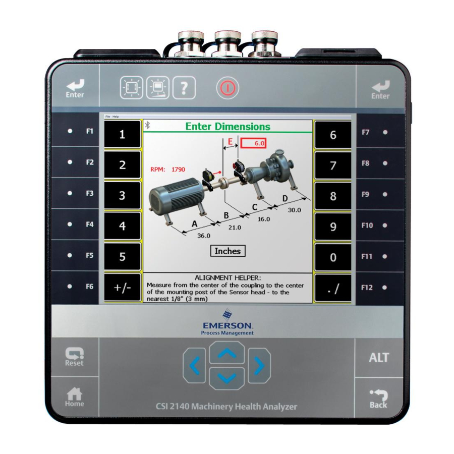
Advanced Laser Alignment The Laser Align Application main menu also displays the number of notes added for the job in the upper right corner of the screen. Remove a note from an alignment job Procedure From the Laser Align Application main menu, press ALT > F1 Notes. Press F11 or F12 to select a note from the Assigned Notes list. - Page 206 Advanced Laser Alignment View machine moves and align the machine. You can calculate moves for extra feet, use the predict mode, view the tolerance plots, or perform a live move from under this step. 7.5.1 Enter machine dimensions - horizontal alignment This is the first step in performing horizontal alignment.
- Page 207 Advanced Laser Alignment This parameter is used to establish alignment tolerances. If you have a variable speed machine, enter the highest RPM at which the coupling operates. Enter machine dimensions and press Enter. Dimension* Measurement description Inboard foot to the outboard foot of the machine on the left Inboard foot of the machine on the left to the center of the coupling Center of the coupling to the inboard foot of the machine on the right Inboard foot to the outboard foot of the machine on the right...
- Page 208 Advanced Laser Alignment Prerequisites Enable the thermal growth option. See Section 7.4.8. Procedure After entering machine dimensions, press Enter. Enter thermal growth information. The steps vary based on the thermal growth conversion option you selected. Growth At Feet Figure 7-18: Growth at feet a.
- Page 209 Advanced Laser Alignment Growth At Profile Figure 7-19: Enter profile dimensions a. Enter dimensions for the profile locations and their relationship with respect to the machine feet locations as defined in the Enter Dimensions screen and press Enter. Dimension* Measurement description Profile P4 to the center of the outboard foot of the machine on the left.
- Page 210 Advanced Laser Alignment c. Press Enter. This displays the Growth At Feet screen showing the calculated vertical and horizontal thermal growth at each machine foot. If one or both machines experience downward growth during operation, negative numbers are displayed for the vertical direction. If one or both machines experience growth to the right during operation, negative numbers are displayed for the horizontal direction.
- Page 211 Advanced Laser Alignment Use the Set Gap and Set Offset keys to enter gap and offset growth for the specified location. Use the Set Direction keys to define whether the coupling gap is open at the top or bottom and to set the coupling offset location (whether the left machine is higher than the right or vice versa).
- Page 212 Advanced Laser Alignment Dimension* Measurement description Diameter of the coupling. Center of the inboard foot on the left machine to the center of the coupling. *Measure to the nearest 1/8 inch (3 mm). b. Use the left or right arrow keys to modify where the target dial indicator readings are taken and press F2 Change Sensor Location.
- Page 213 Advanced Laser Alignment Dimension* Measurement description Center of the inboard foot of the left machine to the dial indicator location on the left machine shaft. Dial indicator location on the left machine shaft across the coupling to the dial indicator location on the right machine shaft. *Measure to the nearest 1/16 inch (1.5 mm).
- Page 214 Advanced Laser Alignment Auto Sweep Figure 7-23: Auto Sweep a. Position the laser and sensor at a starting angle (any angle). Make sure the laser and sensor are within 2° of each other. The position of the laser fixtures is marked on the screen with a black line on the green circle.
- Page 215 Advanced Laser Alignment Pass Mode Figure 7-24: Pass Mode a. Position the laser and sensor at a starting angle (any angle). The laser fixtures do not have be in alignment with each other during this step. b. Press Initialize Heads. c.
- Page 216 Rotate the laser fixtures while stopping at points to take a reading. Press Accept Readings after stopping at each point. You need to collect a minimum of 3 data points (samples) over a sweep arc of at least 45°. However, Emerson recommends 8 data points over a sweep arc of 90°.
- Page 217 Advanced Laser Alignment Auto 4 Point Figure 7-26: Auto 4 Point a. Position the laser and sensor at a starting angle (ideally at the first cardinal position, that is 0°). The laser and sensor angles should be within 2° of each other and within 3° of the active cardinal position (0°, 90°, 180°, and 270°).
- Page 218 Advanced Laser Alignment Manual 4 Point Figure 7-27: Manual 4 Point a. Position the laser and sensor at a starting angle (ideally at the first cardinal position, 0°). The laser and sensor angles should be within 2° of each other and within 3° of the active cardinal position (0°, 90°, 180°, and 270°), if possible.
- Page 219 Advanced Laser Alignment If the Review Results option is enabled, review the results, view the tolerance plots, or repeat the reading. Section 7.4.6 for more information on how to enable reviewing of results. After reviewing results, press Enter to advance to the next step (Move Machine). 7.5.4 Check for soft foot Checking for soft foot is available only for Advanced horizontal alignment jobs.
- Page 220 Advanced Laser Alignment Table 7-1: Foot pre-check results and meanings Soft foot Result Meaning Soft foot measurement is within the specified tolerance. Soft foot measurement is 1 to 2 times the specified tolerance. Soft foot measurement is 2 to 3 times the specified tolerance.
- Page 221 Advanced Laser Alignment Figure 7-28: Soft foot Correcting this type of problem with a full shim can make the condition worse (see Figure 7-29, figure on the left). Correction should be determined with a set of thickness gauges (feeler gauges). The result is usually a wedge shim (see Figure 7-29, figure on the right).
- Page 222 Advanced Laser Alignment Soft foot Soft foot evaluation provides you with a sense of severity without showing numbers. Numbers are not used because, most of the time, they are mistaken for the value of the shims, which is incorrect. When the numbers are calculated, they are compared against the tolerance (usually 0.5 mils/inch).
- Page 223 Advanced Laser Alignment Reviewing results is useful when repeatability of the data is a concern. Prerequisites Enable reviewing of alignment measurement results. See Section 7.4.6. Procedure After acquiring alignment data, press Enter. Review the alignment measurement results. The Review Measurements screen shows the vertical offset, vertical angle, horizontal offset, horizontal angle, the date and time the data was acquired, a symbol depicting the alignment method used to acquire the data, and a checkmark if the data is used in the average calculation.
- Page 224 Advanced Laser Alignment Icon Description The alignment method is Auto Sweep, Manual Sweep, or Pass Mode. The background is green if the data quality is good, yellow if the data quality is poor, and red if the data quality is bad. Data quality here is the correlation factor computed from the sine fit to the data.
- Page 225 Advanced Laser Alignment 7.5.6 Align the machine - horizontal alignment After you acquire alignment data, the Laser Align Application automatically advances to the next step, which is to make adjustments on the machines to align them (Move Machine), if necessary. After completing this step, the Move Machine function on the Laser Align Application main menu is marked with an X.
- Page 226 Advanced Laser Alignment Figure 7-32: Horizontal machine move For horizontal machine moves, if the required movement is positive, the amount of movement is shown below the machine at the appropriate foot with a down arrow. If the required movement is negative, the amount of movement is shown above the machine at the appropriate foot with an up arrow.
- Page 227 Advanced Laser Alignment c. Press F6 Switch Move Type to select a move type. You can choose vertical, horizontal, or vertical and horizontal. d. Press F8 Data Detail to view the tolerance plots. The tolerance plots are a graphical representation of the alignment condition of the machine.
- Page 228 Advanced Laser Alignment Figure 7-33: View data - horizontal alignment MHM-97432 Rev 7...
- Page 229 Advanced Laser Alignment Figure 7-34: View data - vertical alignment Optionally, you can do the following: a. Press F3 Display Actual Data to show the position of the laser beam on each target or F3 Zero Top Reading to display the actual data readings with the top reading adjusted to zero.
- Page 230 Advanced Laser Alignment You can calculate vertical and horizontal machine moves for up to four machine foot locations in addition to those defined for the job. Procedure From the Vertical Move, Horizontal Move, or Dual Move screens, press F5 Alternate Move to choose the machine component where the extra foot is located.
- Page 231 Advanced Laser Alignment This displays the movement required to align the machine vertically or horizontally. The bull's-eye target compares the total misalignment to the target tolerance. Each circle in the bull's-eye target has a different meaning: red—more than two times the tolerance, yellow—between one and two times the tolerance, green—within acceptable the tolerance, green with a star—within excellent tolerance.
- Page 232 Advanced Laser Alignment The bottom half of the CSI 2140 screen shows a bull's-eye target and a shaft centerline plot representing the alignment condition of the machine. The shaft centerline plot includes a "V" shape indicating the acceptable angular tolerance on the machine as well as a bracket at the base of the "V"...
- Page 233 Advanced Laser Alignment Figure 7-36: Horizontal live move Perform the live move with the laser fixtures at any rotational position. Before proceeding, make sure that the laser fixtures are located at a position where they can remain stable throughout the alignment process. The average laser and sensor angle position is displayed in the middle of the screen.
- Page 234 A live machine move is not a reliable indicator of the final alignment condition of a machine. There will be variability in the alignment data due to shaft clearances, bearing faults, base deterioration, etc. Emerson recommends acquiring a new set of alignment data after performing a live move.
- Page 235 Advanced Laser Alignment After viewing tolerance plots in QuickSpec mode, press Enter and select from the following: • Finished—to complete the job. • Retake Data—to retake data. • Align Standard Machine—to enter machine dimensions and consider the job as a regular horizontal alignment job.
-
Page 236: Vertical Alignment
Advanced Laser Alignment Shim values are equivalent to raising the machine. In this case, all shim values are positive. When correcting angular misalignment, keep the flange offset movement to a minimum. After shimming is complete, re-tighten bolts and take a new set of readings. - Page 237 Advanced Laser Alignment Figure 7-37: Enter dimensions - vertical alignment Prerequisites Ensure the laser and sensor are mounted on the machines. Create and/or activate an alignment job and set up the job parameters. An alignment job is needed to perform alignment. Set the measurement units for the alignment job.
- Page 238 Advanced Laser Alignment Dimension* Measurement description *Measure to the nearest 1/8 inch (3 mm). Note You need to enter all machine dimensions. On the Define Flange screen, enter the dimensions for the flange location where moves are to be made and press Enter. Section 7.6.2 for more information.
- Page 239 Advanced Laser Alignment Prerequisites Enable the Custom Pattern option when defining the flange. See Section 7.6.2 for more information. Procedure From the Define Flange screen, press Enter. This displays the Custom Pattern screen. Use the up or down arrow keys on the analyzer to select an item (shaft center or bolt) to edit, or press F9 Item to Edit to select an item to edit and press Enter.
- Page 240 Advanced Laser Alignment 7.6.4 Acquire alignment data - vertical alignment After you enter machine dimensions, the Laser Align Application automatically advances to the next step, which is to acquire alignment data by sweeping the laser and sensor (Sweep Heads). After completing this step, the Sweep Heads function on the Laser Align Application main menu is marked with an X.
- Page 241 Rotate the laser fixtures to the next location where you want to take a reading and repeat steps 3 and 4. You can take at least three readings over a rotational arc of 45°. However, Emerson recommends a minimum of eight data points over a sweep arc of at least 90°.
- Page 242 Advanced Laser Alignment Procedure After acquiring alignment data, press Enter. Review the alignment measurement results. The Review Measurements screen shows the offset and angular data, the date and time the data was acquired, a symbol depicting the alignment method used to acquire the data, and a checkmark if the data is used in the average calculation at the bottom of the screen.
- Page 243 Advanced Laser Alignment Icon Description This shows the alignment method used, which is Manual Sweep for vertical alignments. The background is green if the data quality is good, yellow if the data quality is poor, and red if the data quality is bad.
- Page 244 Advanced Laser Alignment Figure 7-40: Angular Move Optionally, you can do the following: a. Press F1 Raise Machine to display the shim values equivalent to raising the machine. This causes all shim values to be positive. b. Press F2 Median to display shim values equivalent to making the smallest moves. This causes the shim values to be centered about an average.
- Page 245 Advanced Laser Alignment Figure 7-41: Offset Move The bull's-eye target compares the total misalignment to the target tolerance. Each circle in the bull's-eye target has a different meaning: red—more than two times the tolerance, yellow—between one and two times the tolerance, green—within acceptable tolerance, green with a star—within excellent tolerance.
- Page 246 Advanced Laser Alignment 7.6.7 Perform live move - vertical alignment The Live Move option lets you observe the machine movement from the analyzer while you are moving the machine. Procedure From the Offset Move screen, press F12 Live Move. To view the Offset Move screen, press F6 Switch Move Type or press Enter on the Angular Move screen.
-
Page 247: Straightness Measurements
A live machine move is not a reliable indicator of the final alignment condition of a machine. There will be variability in the alignment data due to shaft clearances, bearing faults, base deterioration, etc. Emerson recommends acquiring a new set of alignment data after performing a live move. - Page 248 Advanced Laser Alignment Figure 7-43: Enter dimensions - straightness measurements Prerequisites Ensure the laser and sensor are mounted on the machines. Create and/or activate a straightness alignment job and set up the job parameters. An alignment job is needed to perform alignment. Set the measurement units for the alignment job.
- Page 249 Advanced Laser Alignment 7.7.2 Acquire straightness data After you enter the profile dimensions, the Laser Align Application automatically advances to the next step, which is to acquire straightness data (Acquire Data). After completing this step, the Acquire Data function on the Laser Align Application main menu is marked with an X.
- Page 250 Advanced Laser Alignment Figure 7-44: Acquire straightness data Use the left or right arrow keys on the analyzer to move between segments, and press F3 Accept Readings to take a reading. A selected segment is denoted by a red box below the segment number. Repeat step 4 for all segments in the machine train.
- Page 251 Advanced Laser Alignment Figure 7-45: Surface profile Review the surface profile plot. Segment readings are plotted on the graph with lines connecting each reading. A reference line is displayed horizontally along the origin of the Y axis. When the analyzer plots the straightness profile, the relationship of the measured readings to the reference line is plotted instead of the actual measured readings.
-
Page 252: Plots
Advanced Laser Alignment d. Press ALT > F3 Cursor Home to place the cursor to the first defined segment. e. Press ALT > F4 Clear Cursor to remove the cursor from the screen. f. Press ALT > F9 Cursor End to place the cursor to the last defined segment. g. - Page 253 Advanced Laser Alignment Figure 7-46: Tolerance plot The tolerance plot displays alignment measurements on an X-Y graph, with line segments connecting consecutive measurements. For a horizontal alignment job, the vertical and horizontal alignment results are displayed on the same plot but are differentiated by the color of the data points.
- Page 254 Advanced Laser Alignment b. Press F2 View Data to review the alignment data in the traditional cardinal positions (0°, 90°, 180°, 270°). See Section 7.5.7 for more information on the View Data screen. c. Press F4 Full Screen to display the plot in full screen. d.
- Page 255 Advanced Laser Alignment From the Review Measurements screen, press F8 Data Detail. Press F1 Display Sine Fit to display the sine fit data plot. Figure 7-47: Sine curve data plot On the sine curve data plot, the amplitude versus degree data is shown. When a cursor is active, the following data values for the selected point are displayed below the plot: •...
- Page 256 Advanced Laser Alignment Note It is not recommended to make moves based on site fit percentages of less than 70%. Sine fit percentages above 90% provide highest repeatability. Optionally, you can do the following: a. Press F1 Delete/Undelete Point to delete or undelete a selected point. The point is not really deleted, but is marked/unmarked so that it is not used when the program fits a sine wave to the data points.
-
Page 257: Transfer Alignment Jobs
Advanced Laser Alignment To remedy this, make sure both the laser and sensor are mounted properly on the shaft of each machine, check the coupling, and acquire new data. When the only place to mount the laser fixtures is on a flexible type coupling, make sure the laser fixtures are mounted on sections of the coupling that flex independently of each other. - Page 258 Advanced Laser Alignment Figure 7-48: Alignment summary report example 7.9.2 Transfer an alignment job to AMS Machinery Manager Prerequisites Connect the analyzer to a PC with AMS Machinery Manager installed and running. Set the connection type on the analyzer. See Section 3.3.3.
- Page 259 Advanced Laser Alignment Set the connection type in Data Transfer. The connection type on the analyzer and on Data Transfer must match. See Section 3.3.5. Procedure From the Laser Align Application main menu, press ALT > F9 Job Manager > F7 Connect for Transfer.
- Page 260 Advanced Laser Alignment 7.9.4 Load tolerance table from AMS Machinery Manager Alignment tolerance tables can only be transferred from the PC to the analyzer. The alignment tolerance table contains the tolerance values for standard and jackshaft tolerances as well as soft foot and FDI tolerance values for horizontal alignment jobs and tolerance values for vertical alignment jobs.
- Page 261 Advanced Laser Alignment Note You can only print alignment summary reports for horizontal and vertical alignment jobs. You cannot print summary reports for straightness alignment jobs. Use the appropriate cable to connect your analyzer to a computer where AMS Machinery Manager is installed, if you are using a wired connection. On the computer, open Data Transfer.
- Page 262 Advanced Laser Alignment MHM-97432 Rev 7...
-
Page 263: Chapter 8 Advanced Transient
Advanced Transient Advanced Transient Topics covered in this chapter: • Advanced Transient overview • Manage jobs • Sensors and inputs • Tachometers • Select a section of the full transient waveform • Set the number and type of plots to display in Advanced Transient •... - Page 264 Advanced Transient After you collect the data, examine it for any changes in pattern, frequency, or amplitude. The changes reveal how the equipment responds to these transient events or what causes these events to occur. 8.1.2 Open or close the Advanced Transient program To open the program, press F11 Adv.
- Page 265 Advanced Transient Figure 8-1: Transient main menu An alternate (ALT) screen includes additional options. The identifier for the job. The equipment description. Where the job file is in the analyzer. If you saved the job to a memory card, "Card" appears. Available internal memory or memory card.
- Page 266 Advanced Transient Option Description View the collected data. This option is available only if you collected F7 Display Data data for the measurement point. Create and edit jobs, save jobs to another memory location, or F8 Job Manager transfer jobs to AMS Machinery Manager. Intentionally blank.
-
Page 267: Manage Jobs
You use can the four-channel functionality to make your Transient data collection quicker and more efficient. Use the CSI 2140 Four-Channel Input Adapter or two splitter cables to allow you to collect data from four points simultaneously. You can then analyze data for problems, such as oil whirl or resonance. - Page 268 Advanced Transient 8.2.5 Change the equipment description for an Advanced Transient job From the Transient main menu, press F8 Job Manager. Use the up and down arrow keys to select a job. Press F4 Edit This Job > F2 Edit Equip Desc. Enter up to 28 characters.
-
Page 269: Sensors And Inputs
Advanced Transient 8.2.9 Activate an Advanced Transient job Activating a job lets you collect data for that job. It is similar to opening a file. Activate a job when you want to change jobs. Procedure From the Transient main menu, press F8 Job Manager. Use the up and down arrow keys to select a job. - Page 270 Input A = Z direction, Input B = X direction, Input C = Y direction. Note When you select Emerson Triax, the following sensor options are set for the A, B, and C inputs: • Sensor Type = Accelerometer •...
-
Page 271: Tachometers
Advanced Transient Press Enter. 8.3.3 Set data units in Advanced Transient Set the data units for each selected input. Procedure Activate a job. From the Transient main menu, press F1 Setup / Acquire Data > F12 Input Setup. For each input, select the units. Press Enter. - Page 272 Advanced Transient Option Description Set the analyzer to power the tachometer. If you enable this option, you F5 Tach Power can leave the switch on for the CSI 430 SpeedVue Sensor during the Laser Speed Detection Analysis Expert. The default is On. Set the trigger to occur on the rising edge or falling edge of a waveform.
-
Page 273: Select A Section Of The Full Transient Waveform
Advanced Transient The setup appears on the Tachometer Setup screen. Press Enter. 8.4.4 Rename a saved tachometer setup in Advanced Transient From the Transient main menu, press ALT > F4 Tach Setup or F1 Setup / Acquire Data > F7 Tach Setup. - Page 274 Advanced Transient Note The selections may be limited by the number of points. The analyzer only displays the points with data. The default is 512. Press Enter. 8.5.2 Set the number of lines in Advanced Transient You can select the number of lines to display. Procedure Activate a job.
-
Page 275: Set The Number And Type Of Plots To Display In Advanced Transient
Advanced Transient Procedure Activate a job. From the Transient main menu, press ALT > F5 Data Display Settings > F5 Set Spectrum Units A. Use the up and down arrow keys to select an option. Press Enter. Repeat these steps for all inputs. Press Enter. -
Page 276: Set Data Collection Parameters
Advanced Transient Set data collection parameters 8.7.1 Setup/Acquire Data The Setup/Acquire Data option on the Transient main menu lets you set the data collection parameters for your job, including: • The Fmax • The sample rate, number, and time • PeakVue technology or Demodulation •... - Page 277 Advanced Transient Procedure Activate a job. From the Transient main menu, press F1 Setup / Acquire Data. Set the following options as necessary. Option Description F3 Set Sample Set the number of samples to acquire every second. Values may range from 25.6 to 51,200.
-
Page 278: Collect Transient Data
Advanced Transient Option Description F11 Store Tach Times (Available only if Tach Trigger is On). Enable or disable tachometer time values to be saved with the measurement point data. Press Enter. Collect transient data Note For orbit plots, the analyzer uses the lowest input channel for the X axis and the next input for the Y axis. -
Page 279: Plot Data In Advanced Transient
Advanced Transient Note Use caution with the Clear Data option. Deleted data cannot be recovered. Procedure From the Transient main menu, use the up and down arrow keys to select a measurement. Press F5 Clear Data. Press Enter. The Transient main menu displays "No Data (Setup Defined)" for the measurement. Plot data in Advanced Transient When a full transient waveform plot displays, a section of waveform represented by two solid vertical lines appears on the plot. - Page 280 Advanced Transient Procedure Use the appropriate cable to connect your analyzer to a computer where AMS Machinery Manager is installed, if you are using a wired connection. On the computer, open Data Transfer. On the analyzer, display the plot for the transient data. You can press F7 Display Data on the Transient main menu, or collect data and view the plot.
-
Page 281: Chapter 9 Ods/Modal
™ from Vibration Analysis, and then export the data to ME'scope VES for analysis. The Advanced Cross Channel program is included with all two and four channel CSI 2140 analyzers. To use the ODS/Modal program: Create a job or activate a saved job. You must use a job to save your data. - Page 282 ODS/Modal Collect the data. Transfer the job to AMS Machinery Manager. ™ Export the job to the ME'scope VES for analysis. Note ™ This manual does not describe exporting data to ME'scope VES , or analyzing the data. 9.1.1 When to collect ODS/Modal data Use modal analysis with mechanical equipment and the structural framework, including fans, pumps, compressors, rolling mills, paper machines, or computer components.
- Page 283 ODS/Modal Figure 9-1: ODS/Modal main menu An alternate (ALT) screen includes additional options. The active measurement point (2) and direction (X). The identifier for the job. Where the job file is in the analyzer. If you saved the job to a memory card, "Card" appears. Data collection status.
- Page 284 ODS/Modal Option Description Change the inputs for each direction. This option is available F4 Change Meas Input only when you collected data for the job, and you have 3 or more inputs set up. This is useful if you want to change the orientation of the triaxial accelerometer, or you want to switch from a triax to single sensors.
-
Page 285: Manage Jobs
ODS/Modal Option Description Intentionally blank. Intentionally blank. 9.1.4 Measurement point abbreviations and symbols Measurement points have a number and a three-letter abbreviation to indicate the direction. Note ™ ME'scope VES uses X, Y, Z. • X, Y, Z: rectangular • R, T, Z: cylindrical •... - Page 286 ODS/Modal 9.2.2 View all saved ODS/Modal jobs From the ODS/Modal main menu, press F8 Job Manager. All the saved jobs display. To sort the jobs, press ALT > F1 Sort by Alphabet or ALT > F3 Reverse Sort Order. 9.2.3 Create an ODS/Modal job When you create a job, you must set up the measurement parameters and the fixed reference parameters.
- Page 287 ODS/Modal Procedure From the ODS/Modal main menu, press F8 Job Manager. Use the up and down arrow keys to select a job. Press F4 Edit This Job > F2 Edit Equip Desc. Enter up to 28 characters. Press Enter. 9.2.6 Activate an ODS/Modal job Activating a job lets you collect data for that job.
-
Page 288: Sensors And Inputs
Input A = Z direction, Input B = X direction, Input C = Y direction. Note When you select Emerson Triax, the following sensor options are set for the A, B, and C inputs: • Sensor Type = Accelerometer •... - Page 289 ODS/Modal 9.3.2 Set up a sensor in ODS/Modal You can set sensor parameters for inputs A, B, C, and D. When you use the CSI A0643TX triaxial accelerometer, input A receives measurements from the z-axis, input B receives measurements from the x-axis, and input C receives measurements from the y-axis. For Modal jobs, the hammer is on your reference channel.
-
Page 290: Tachometers
ODS/Modal Press Enter. Tachometers 9.4.1 Set up a tachometer in ODS/Modal Note By default, the analyzer is set up to use the CSI 404 tachometers. The analyzer supports tachometer/RPM measurements up to 100,000 RPM. Procedure From the ODS/Modal main menu, press ALT > F4 Tach Setup. The Tachometer Setup screen appears. - Page 291 ODS/Modal Option Description View or hide the last RPM the tachometer read and the time between each F10 Show RPM F10 Hide RPM reading. A last time value of 0 indicates the tachometer is continuously reading the RPM. F12 Set Defaults Restore the default values for all tachometer setup options on the screen. Press F6 Save / Recall Setup to save the setup, or press Enter to use the setup without saving it.
-
Page 292: Set Up The Plots
ODS/Modal The Tachometer Setup screen appears. You can also open the Tach Setup option by pressing F8 Job Manager > F4 Edit This Job > F8 Analysis Setup > F7 Tach Setup. From the Tachometer Setup screen, press F6 Save / Recall Setup. Use the up and down arrow keys to select a saved setup. -
Page 293: Set Up The Job
ODS/Modal Option Description Display a waveform from the reference input, and coherence plots Ref Waveform and All Coherence for the other plots. Display a waveform from the reference input, and cross channel Ref Waveform and All phase plots for the other plots. Cross Channel Phase Display a waveform from the reference input, and FRF plots for the Ref Waveform and All FRF... - Page 294 ODS/Modal Option Description Enter the number of points. The number of measurement point F2 Set Number of Points directions and number of points determine the total number of locations to collect data. For example, if the measurement direction is XYZ and 1,024 points are defined, a total of 3,072 locations (1,024 X, 1,024 Y and 1,024 Z) are available in the job.
- Page 295 ODS/Modal 9.6.3 Set the acquisition parameters for an ODS/Modal job From the ODS/Modal main menu, press F8 Job Manager. Use the up and down arrow keys to select a job. Press F4 Edit This Job > F8 Analysis Setup. Set up the following options as necessary. Option Description F2 Set Spectra Params Set the Fmax, Fmin, and lines of resolution.
- Page 296 ODS/Modal Press F3 Recall Setup. Rename an acquisition parameter setup in ODS/Modal From the ODS/Modal main menu, press F8 Job Manager. Press F4 Edit This Job > F8 Analysis Setup > F6 Save / Recall Setup. Use the up and down arrow keys to select a setup. Press F4 Edit Setup Desc.
- Page 297 ODS/Modal Option Description Set the reference input to A, B, C, or D. Do not move the fixed reference F9 Set Fixed Ref Input sensor during the job. The default is input A. If you disable the reference input on the Input Setup screen, "???" displays next to the F9 Set Fixed Ref Input key.
-
Page 298: Collect Ods/Modal Data
ODS/Modal Collect ODS/Modal data Note If you cancel data collection, the existing data is not overwritten. After data is stored on a measurement point, you can copy it to other measurement points using the Copy Data option. Procedure Activate a job. Ensure the job parameters are set as desired. - Page 299 ODS/Modal From the ODS/Modal main menu, press F12 Show Unmeas Points. If a measurement point has data, the measurement point or its direction does not appear. Press F12 Show Measured Points to view only the measured points or all of the points in the job.
-
Page 300: Display The Data For A Ods/Modal Measurement Point
ODS/Modal Procedure Activate a job. From the ODS/Modal main menu, use the up and down arrow keys or the F9 Point Search key to select a measurement point. Press F5 Clear Data. Press Enter. The analyzer clears the data from only the active point. 9.7.5 Redo an ODS/Modal measurement You can store one set of data per measurement point/direction. -
Page 301: Print An Ods/Modal Plot To Ams Machinery Manager
ODS/Modal Print an ODS/Modal plot to AMS Machinery Manager Prerequisites • On the analyzer, press Home > ALT > F2 General Setup > F6 Set Print Mode and ensure the default print mode is set to Send to PC. • Ensure the same connection type is set on the analyzer and in Data Transfer. - Page 302 ODS/Modal The analyzer begins creating and saving the file to the memory card. The progress is displayed on the screen. MHM-97432 Rev 7...
-
Page 303: Chapter 10 Balance
Balance Balance Topics covered in this chapter: • Balance overview • Manage jobs • Job Setup • Sensor Setup • Measurement Plane Setup • Weight Plane Setup • Acquire Data • Balance correction • Trim run • One-run balance job •... - Page 304 Balance Set up the job parameters, including balance mode, balance specification, speeds, tachometers, sensors, measurement planes, measurement points, and weight planes. Acquire runout (optional), reference run, and trial run data to calculate the balance correction. View the calculated balance correction. Acquire trim runs to ensure the machine is within the balance specification based on your site or the machine manufacturer.
- Page 305 Balance Figure 10-1: Balance main menu Displays an X for each completed step in the balance procedure. The steps are Job Setup, Acquire Data, View Corr, and Trim Run. The identifier for the job. The equipment description. Number of completed trim runs. Number of attached notes.
- Page 306 Balance Option Description Acquire trim runs to ensure the machine is within the balance F6 Trim Run specification based on your site or the machine manufacturer. Close Balance and return to the Home screen. F7 Exit Balance Intentionally blank. Intentionally blank. Intentionally blank.
- Page 307 Balance 10.1.3 Single-plane Balance job overview A new single-plane job has the following steps: Create a new job or activate an existing job. Set up the job parameters. (Optional) Acquire runout data. Acquire reference run (as-is) data. Add or remove trial weights. Acquire trial run data.
-
Page 308: Manage Jobs
Balance A balance weight added to one end affects the vibration levels at both ends. The primary effect is the balance weight on the nearest support bearing. Cross effect is the effect of the balance weight on the opposite support bearing. Multiple plane balancing takes into account both primary and cross effect when calculating corrections. - Page 309 Balance Press Enter. 10.2.4 Edit the description for a Balance job You can change the default or saved IDs and descriptions for a job. By default, each job is given a unique Job ID. A Job ID is required. Other options are optional and are printed on reports from UltraMgr.
- Page 310 Balance 10.2.6 Copy a Balance job Create a copy of a job in the same memory location. The new copy is highlighted, but not activated. You must activate the job. If you want to copy or move the job from internal memory to a memory card, use the File Utility on the Home screen.
-
Page 311: Job Setup
Balance 10.3 Job Setup After you create or activate a job, set up or review the parameters in Job Setup. An X appears next to Job Setup on the Balance main menu when you complete this step. Depending on the Balance mode, one or three screens are required to setup the job parameters. - Page 312 Balance • You cannot view the reference run data or last set of trim run data from the trial run. Change the mode You can change the mode for a job at any time. When you change the mode, the setup parameters reset to their default values and any data stored in the job is deleted.
- Page 313 Balance Option Description F2 Meas. Planes Enter a number between 1 and 8 and press Enter. Enter a number between 1 and 8 and press Enter. The maximum number F3 Meas. Points depends on the number of measurement planes. F8 Enter Balance Enter a value between 0.001 and 10,000 for the desired vibration level for the equipment, and press Enter.
- Page 314 Balance Option Description Repeatedly press F2 until the 2 planes, 2 sensors option appears. F2 Toggle Config. Enter a value between 0.001 and 10,000 for the desired vibration level F8 Enter Balance for the equipment, and press Enter. The units are the same as the Spec.
- Page 315 Balance Postrequisites In Advanced Balance mode, set up the measurement plane. See Section 10.5. 10.3.4 Tachometers Set up a tachometer in Balance By default, the analyzer is setup for CSI 404 tachometers. Pseudo Tach must be disabled for the Balance program. When the pseudo tach is disabled, a standard 1x tach is produced.
- Page 316 Balance Save a tachometer setup in Balance The saved setup is accessible from all other programs on the analyzer. Procedure From the Balance main menu, press F3 Job Setup > F10 Tach Config > F6 Tach Setup. From the Tachometer Setup screen, press F6 Save / Recall Setup. Use the up and down arrow keys to select Empty or another tachometer setup.
- Page 317 Balance Set the tachometer angle The tachometer location identifies the tachometer reference pulse for future setup, on graphs, and in some special calculations performed in Calculator Mode. The location is indicated by a “T”. The analyzer does not use tachometer location to calculate the balance correction.
-
Page 318: Sensor Setup
Balance Note This is available only in Advanced Balance mode. Procedure From the Balance main menu, press F3 Job Setup > F11 Speed Setup. Set the following options as necessary. Option Description F3 Delta RPM Enter a number between 0 and 500 to set the valid running speed range for all speeds. - Page 319 Balance If you define two measurement points, 90 degrees apart, for each measurement plane, you can see if both axes react similarly. Occasionally, equipment does not react symmetrically due to a significant difference in constraint between axes or resonance. Note You can define up to three sensors for each measurement plane.
- Page 320 Press Enter. 10.4.4 Channels and measurement points If the CSI 2140 Four-Channel Input Adapter is enabled, define one channel for each measurement point. For example, assign input A to measurement point 1 (IBH) and channel B to measurement point 2 (IBV).
- Page 321 Balance Option Description The analyzer does not use the CSI 2140 Four-Channel Input Adapter or external multiplexer. The analyzer acquires all data through the same channel, and you must manually start and accept each measurement. The CSI 2140 Four-Channel Input Adapter controls software that switches between channels.
-
Page 322: Measurement Plane Setup
Balance 10.4.7 Enable or disable the runout measurement Runout is an optional measurement acquired using a displacement sensor during a slow roll of the rotor. A slow roll means the rotor rotates so slowly that readings from the sensors only detect mechanical irregularities on the rotor surface, not vibration. Use runout data to help normalize the balance data. - Page 323 Balance 10.5.1 Measurement points A measurement point is where you collect a measurement on the equipment. You must define at least one measurement point. The default setup distributes the points equally among the defined measurement planes. For example, if you set up seven points and three planes, plane 1 has three points, plane 2 has two points, and plane 3 has two points.
- Page 324 Balance 10.5.2 Add a measurement point to a Balance job You can add up to three measurement points for a measurement plane. The points are added at the end of the list. Note This is available only in Advanced Balance mode. Procedure From the Balance main menu, press F3 Job Setup.
-
Page 325: Weight Plane Setup
Balance 10.5.4 Set up the measurement points on measurement planes From the Balance main menu, press F3 Job Setup. Press Enter or F4 Meas Plane Setup. The Measurement Plane Setup screen appears. Ensure the correct measurement plane is displayed at the top of the screen. Press Enter to go to the next plane, if necessary. - Page 326 Balance Where to place the weights - discrete or continuous A weight plane is discrete or continuous. Discrete weight planes let you place weights only at a specific, numbered positions. Continuous weight planes let you place weights at any position on the rotor, and do not display numbered positions. You can define both types in the same job.
- Page 327 Balance Note After you collect trial run data, you cannot change the weight locations. Procedure From the Balance main menu, press F3 Job Setup. Press F5 Weight Plane Setup or Enter until the Weight Plane Setup screen appears. Press F8 Toggle Discrete Contin to select Continuous or Discrete. Continuous weight planes let you place weights anywhere, and discrete weight planes let you set weights only at specified locations on the plane.
-
Page 328: Acquire Data
Balance 10.6.3 Set the weight plane radius You can set the trial and trim weight placement radius. Weight plane radius ensures you use the same radius in the job. Use this option as a reference and for future setups only. This setting is optional. - Page 329 Balance Figure 10-3: Example of graphs and information displayed Vibration compared to the balance specification (the circle). X appears within the circle when vibration is within the balance specification. A cross hair (+) symbol indicates the endpoint of the averaged phase/ magnitude vector. A vector line with a terminating square symbol on one end indicates the instantaneous vector.
- Page 330 Balance Option Description Change the direction of the shaft rotation for the current F4 Toggle Direction Rotation diagram. Intentionally blank. F6 Accept Data Save the collected data to the job. Intentionally blank. Clear the averaged magnitude and phase data. When the F8 Clear Data data is cleared, the data average starts again.
- Page 331 Attach one or more displacement sensors to the analyzer. • If you use more than one sensor and do not use the CSI 2140 Four-Channel Input Adapter, ensure you connected the proper cables before collecting data. Collect the measurement for the appropriate input.
- Page 332 • Ensure the machine is running. • If you use more than one sensor and do not use the CSI 2140 Four-Channel Input Adapter, ensure you connected the proper cables before collecting data. Collect the measurement for the appropriate input.
- Page 333 You may want to acquire a frequency signature at the points to determine the other frequencies and consider other possible causes. Emerson recommends you use the same vibration units (acceleration, velocity, or displacement). Changing units can dramatically change the apparent distribution of energy.
- Page 334 Balance Ratio Status Greater than 8:1 High Ratio alert is triggered for two sensors close to Resonance Likely 90° apart, and the phase change is approximately 0° or 180° Axial 1xRPM vibration is greater than radial Note This is available only in Advanced Balance mode. Imbalance usually causes higher radial vibration magnitudes at rotational frequency than axial magnitudes.
- Page 335 Balance Enter the weight and location of the trial weight into the Estimate Trial Weights screen. Start the equipment. Acquire data at all measurement points and speeds. Repeat these steps for each trial run in your job. Where to place the trial weights Trial weights determine the effect on the equipment when you add or remove a known weight at a known location.
- Page 336 Balance • If you use more than one sensor and do not use the CSI 2140 Four-Channel Input Adapter, ensure you connected the proper cables before collecting data. Collect the measurement for the appropriate input. Procedure From the Balance main menu, press F4 Acquire Data > Acquire Trial Run Data for the appropriate trial run.
- Page 337 Balance Collect data until the magnitude is stable and phase varies by no more than 5 degrees in the Data Stability graph. Press Accept Data to save the data. If you selected Auto for the mux option, the Balance program automatically accepts the data and moves to the next point when the phase and magnitude are good for 3 consecutive averages.
-
Page 338: Balance Correction
Balance The analyzer collects new data. 10.7.6 Clear all measurements for a Balance job The Clear Job Data option lets you delete all collected data for a job. The job setup parameters are not deleted. Note Use caution with the Clear Job Data option. Deleted data cannot be recovered. Procedure From the Balance main menu, press ALT >... - Page 339 Balance Procedure From the Balance main menu, press F5 View Corr. Review the correction and verify the accuracy of the information. Each weight and location on the weight plane is color-coded and matches the graph at the bottom of the screen. Figure 10-5: Balance correction example - Advanced Balance mode Press Leave Trial Wt.
-
Page 340: Trim Run
Balance 10.9 Trim run After you view the balance correction, acquire trim run data to get the vibration within the balance specification you set in Job Setup. After a trim run is complete, the trim correction displays. The trim run has the following steps: Install the correction weight. - Page 341 Attach one or more vibration sensors and the tachometer to the analyzer. • If you use more than one sensor and do not use the CSI 2140 Four-Channel Input Adapter, ensure you connected the proper cables before collecting data. Collect the measurement for the appropriate input.
- Page 342 Balance Collect data until the magnitude is stable and phase varies by no more than 5 degrees in the Data Stability graph. Press Accept Data. Repeat the steps above for all measurement points for all trim runs. If you select Auto for the mux option, the Balance program automatically accepts the data and moves to the next point when the phase and magnitude are good for 3 consecutive averages.
- Page 343 Balance • Lines connecting the reference run reading and up to two additional trim readings, always using the last two trim run readings, for each measurement point defined for the plane. • % Down (percent of magnitude change) - Relationship between the most recent trim run reading and the initial reading.
-
Page 344: One-Run Balance Job
Balance 10.10 One-run balance job A one-run balance job, also called trim balancing, lets you use a balance job and its reference run, trial run, and balance correction to balance the same or similar equipment. After equipment is successfully balanced, transfer the balance job to AMS Machinery Manager for storage. -
Page 345: Notes
Balance 10.11 Notes Notes let you make comments and observations about the equipment you are monitoring. After you add the note to the job, it is saved with your measurement data. When you transfer the job to AMS Machinery Manager, the note is included. The analyzer has pre-defined notes you can use. -
Page 346: Balance Summary Reports
Balance 10.11.3 Remove a note from a Balance job From the Balance main menu, press ALT > F3 Notes. Under Assigned Notes, use the up and down arrow buttons to select a note to delete. Press F5 Remove From Job. The note is removed from the Assigned Notes section and your job. - Page 347 Balance Figure 10-7: Summary report example Option Description Job ID set in Job Desc. Job Number Data Taken Date and time you collected the data. User ID set in Job Desc. Technician Notes you attached to the job. Notes Shaft Number Number of shafts defined in Job Desc.
- Page 348 Balance 10.12.1 Print a Balance summary report to AMS Machinery Manager Prerequisites • On the analyzer, press Home > ALT > F2 General Setup > F6 Set Print Mode and ensure the default print mode is set to Send to PC. •...
-
Page 349: Review Balance Data
Balance 10.13 Review Balance data You can view the data collected or manually entered for any of the measurement runs in a job. You cannot edit these values from the Review Data screen. Procedure From the Balance main menu, press ALT > F9 Review/Edit Data. The measurement run appears at the top of the screen. -
Page 350: Manually Enter Data For A Balance Job
Balance 10.14 Manually enter data for a Balance job You can manually enter or edit speed, magnitude, and phase information for a measurement in a job. Modify values to review additional scenarios or enter data you did not collect. The required measurements are displayed with the first measurement point highlighted. - Page 351 Balance Calculator Mode Recommended use Calculate a correction that combines several weights on the rotor into one Sum Weights weight. See Section 10.15.2. The available balance weights do not match the balance or trim correction. Adjust Fixed Weights Section 10.15.3. Calculate the weight locations to address the static and couple Static/Couple Analysis components of the imbalance.
- Page 352 Balance Calculator Mode Recommended use Calculate a value in units of acceleration, velocity, and displacement. Units Conv Note This is available only in Advanced Balance mode. Section 10.15.9. 10.15.1 Determine another location to place weights The Split Angle option lets you calculate a new location for the weights if you cannot place them at the location specified in the balance correction.
- Page 353 Balance If you opened Split Angle from a trim run, press F12 Insert to Trim Weight to send the calculated solution to the Trim Run Applied Weight entry screen. Press F7 Split Angle Calc. to exit and return to the calculation screen. 10.15.2 Combine multiple weights on a rotor The Sum Weights option lets you enter up to three known or desired weights and angular...
- Page 354 Balance Procedure From the Balance main menu, press ALT > F6 Calculator Mode > F4 Adjust Fixed Weights. Set the following options as necessary. Option Description F2 View Balance View the last calculated balance correction. This option displays only if the Corr.
- Page 355 Balance Note When the job has discrete weight positions and you import from the Balance Correction screen, the analyzer converts the discrete positions to continuous positions. Procedure From the Balance main menu, press ALT > F6 Calculator Mode > F5 Static Couple Analysis. Set the following options as necessary.
- Page 356 Enter the sensor/phase lag in degrees introduced by the sensor. For F6 Enter Sensor Emerson supplied accelerometers, sensor lag is normally 0 degrees. The default is 0. Enter the measurement points to use. You can average all readings in a...
- Page 357 Balance Option Description Enter the effect of the mechanical amplification on the vibration F11 Enter Amp. Factor magnitude resulting from an amount of imbalance. Enter a unitless value between 0.0001 and 20.000. The default is 3. Note Amplification factors increase as the rotational frequency moves closer to the critical frequency.
- Page 358 Balance Option Description View the last calculated balance correction. This option displays only if F2 View Balance Corr. the analyzer calculated a balance correction and you accessed Circumference Conversion from the Trim Run Applied Weight menu. Enter the desired angle in degrees, typically the calculated correction F3 Enter Desired Angle angle, or import it from the balance correction.
- Page 359 Balance Option Description Enter the desired weight between 0.00 and 10,000, typically the F3 Enter Known Weight calculated correction weight, or import it from the Balance Correction screen. The default is 0. You cannot import discrete positions. This field is unitless.
- Page 360 Balance Option Description Select the weight plane to use. You may want to select the plane F3 Select Weight Plane nearest the measurement plane that has the readings you want to use. The default is weight plane 1. Enter the weight of the rotor between 0.00 and 100,000 lbs or 0.00 F4 Enter Rotor Weight and 45,454.54 kg.
-
Page 361: Tips And Additional Information
Balance Procedure From the Balance main menu, press ALT > F6 Calculator Mode > F11 Units Conv. Enter the values and the units you want to convert. Option Description F2 Enter Mag. Enter the magnitude of the vibration units to convert. Enter a value between 0.00 and 100,000. - Page 362 Balance Key concepts for balancing machines • Imbalance causes vibration to occur at the rotational frequency (1xRPM) of the imbalanced rotor. • The vibration is directly proportional to the amount of imbalance. Doubling the amount of the imbalance doubles the amount or magnitude of the vibration. •...
- Page 363 Use the CSI 2140 Four-Channel Input Adapter to avoid switching cables or moving sensors between measurement points Use the CSI 2140 Four-Channel Input Adapter or two splitter-Y cables and four sensors to eliminate the need to switch or move sensors on most balancing jobs.
- Page 364 Balance Store every balance job for later reference Use AMS Machinery Manager Data Transfer to transfer the job from the analyzer to the database. Save jobs to reduce setup time when you need to balance the equipment again. The necessary setup and dynamic data for one-run balancing are already available, which reduces the time you spend balancing the equipment.
- Page 365 Balance 10.16.4 Identify the correction planes You can balance a rotor system exactly in N+2 planes (where N = the number of shaft criticals below operating speed). Most mechanical systems are designed to operate below their first shaft critical, so use 0 + 2 = 2 planes. Virtually all systems operate below their fourth critical, so use 3 + 2 = 5 planes.
-
Page 366: Balance Accessories
Balance Issue Potential solution The measured amplification The cause may be a rotational frequency close to a resonance that is factor is greater than six. amplifying the vibration. Check the resonant frequencies. Slight changes in weight size and location cause dramatic changes in the apparent degree of imbalance. - Page 367 Use the selected scale for all readings. Degree scaling correlates directly to the Emerson convention of measuring angles and phase in degrees counter to rotation.
- Page 368 Balance Place the Balancing Compass on an axial face with the indicator needle pointing at 0 degrees. Figure 10-9: Attach and zero Turn the rotor until the indicator reads the desired angular position from the applicable scale. This position is now aligned with the stationary reference. Figure 10-10: Turn the rotor Determine the position of a sensor or tachometer pick up...
- Page 369 Balance Attach the Balancing Compass to any axial face of the rotor so you can see it throughout one rotation. This includes the end of the shaft, the axial face of the rotor itself, or the axial face of anything attached to the shaft, such as a sheave or coupling.
- Page 370 Balance Double scale 0-360° clockwise 0-360° counter clockwise Magnetic backing Requires vertical orientation on axial face of the shaft or rotor 10.17.2 Clamp-on reusable trial weights The CSI Model 8BA20 Trial Weights Assortment includes nine reusable clamp-on trial weights. Weights are clamped on by using knurled cup point set screws in combination with cone point set screws on the opposing side.
- Page 371 Balance Note As a practical matter of safety, Emerson recommends using trial weights that are securely bolted or welded to the rotor being balanced. Emerson does not warrant the applicability or safety of using any weight glued or clamped onto a rotor, including those contained in this kit.
- Page 372 Balance As would be expected, both the 2nd and 3rd configurations proved to hold considerably better than having set screws on only one side. The 3rd configuration usually resulted in some performance improvement over the 2nd configuration however, it gave less consistent results (probably due to the difficulty in getting all the set screws torqued uniformly).
- Page 373 Balance Figure 10-15: Series A MHM-97432 Rev 7...
- Page 374 Balance Figure 10-16: Series B MHM-97432 Rev 7...
- Page 375 Balance Figure 10-17: Series C 10.17.3 Approximate hardware weights The information below lists calculated weights of both coarse thread (UNC) and fine thread (UNF) bolts. This is very useful in any balancing procedure when you use bolts to add balance weight. Weights are calculated for the following bolt hardware: •...
- Page 376 Balance Material Process Brass Multiply weight by 1.0766 To convert ounces to grams, multiply the weight in ounces by 28.3495. MHM-97432 Rev 7...
-
Page 377: Appendix A Technical Specifications
Connecting to a computer • Waste Electrical and Electronic Equipment • • Industry Canada The specifications in this chapter apply to the CSI 2140 analyzer. Hardware specifications Physical dimensions Dimensions 8.8" (248 mm) high, 1.57" (40 mm) deep, 8.9" (226 mm) wide Weight 3.95 lbs (1.79 kg) -
Page 378: Measurement Specifications
Technical specifications Battery pack Type Rechargeable Lithium-Ion battery pack Volts 7.2 volts (Nominal) protected output LEDs On pack LED readout Capacity 10+ hours of continuous use Recharge time 3-4 hours (Nominal) Charging temperature 50° to 95° F (10° to 35° C) Measurement specifications Frequency analysis A/D converter... -
Page 379: Input Specifications
Technical specifications Data storage capacity External memory SD (Secure Digital). Virtually unlimited memory with off the shelf SDHC SD cards up to 32 GB. For optimal performance, use a SD memory card with a speed class of 10 or higher. To verify the speed class of your memory card, refer to the label on the memory card or the documentation for the memory card. - Page 380 Technical specifications Input sensor types Portable sensors Accelerometers, velocity probes, RPM/tachometer probes, temperature sensors, flux coil, current clamp, pressure sensors, triaxial accelerometers, impact hammer Installed sensors Any vibration or dynamic sensor with a voltage output; any DC-type signal Input unit types Vibration Signals Units Acceleration...
-
Page 381: Connecting To A Computer
Technical specifications Connecting to a computer Requirements Connections/output USB 2.0, 100M Ethernet Compatible software AMS Machinery Manager version 5.6 or greater. Refer to www.assetweb.com/mhm under AMS Machinery Manager software for the most current operating requirements. Waste Electrical and Electronic Equipment Marking for the Waste of Electrical and Electronic Equipment in accordance with Article II (2) of Directive 2012/19/EU (WEEE). -
Page 382: Industry Canada
• Consult the dealer or an experienced radio/TV technician for help. Trade Name: Machinery Health Analyzer Model Number: CSI 2140 Industry Canada This device complies with Industry Canada licence-exempt RSS standard(s). Operation is subject to the following two conditions: (1) this device may not cause interference, and (2) this device must accept any interference, including interference that may cause undesired operation of the device. -
Page 383: Appendix B View And Control Your Csi 2140 From A Pc
Display Viewer. Ensure your standby timer is properly set for your tasks. Note You can run multiple CSI 2140 Remote Display Viewers on a PC at one time. However, USB can be used for only one connection. Ethernet and wireless can be used simultaneously, but you must use a different Host Port ID for each of these two connections. -
Page 384: Load The Csi 2140 Remote Display Viewer Onto Your Csi 2140
Load the CSI 2140 Remote Display Viewer onto your CSI 2140 If CSI 2140 Remote Display Viewer is not installed on your analyzer or you need to load a newer version, use the procedure below. You need to connect the analyzer to AMS Machinery Manager Data Transfer to load the CSI 2140 Remote Display Viewer. -
Page 385: View And Control The Csi 2140 From Your Pc
Use the CSI 2140 Remote Display Viewer to display the CSI 2140 screen onto your PC screen. After you display the CSI 2140 screen, you can use your PC to remotely control the analyzer. You can use USB, Ethernet, or wireless to connect the analyzer to your PC. - Page 386 You can use a Host Port ID other than the default of 10078. However, you must enter the same Host Port ID on the analyzer and in the CSI 2140 Remote Display Viewer. Do not use the same Host Port ID as AMS Machinery Manager Data Transfer. The default for Data Transfer is 10077.
-
Page 387: Transfer Files While Using The Csi 2140 Remote Display Viewer
Remote Display Viewer. Ensure your standby timer is properly set for your tasks. To close the CSI 2140 Remote Display Viewer, press Home > F5 Comm Setup > ALT > F5 Remote Display Stop, and then close the PC program (2140RemoteHost.exe). -
Page 388: View The Version Number Of The Csi 2140 Remote Display Viewer
Transfer View the version number of the CSI 2140 Remote Display Viewer Open the CSI 2140 Remote Display Viewer (2140RemoteHost.exe) on your PC. Select a connection type and click OK. Click Help > About CSI 2140 Remote Display Viewer. The version number and build date are displayed. - Page 389 4 channels, or 2 to 4 channels. Use AMS Machinery Manager or AMS Machinery Manager Standalone Data Transfer to connect the analyzer to your PC. Use the CFGxxxxxx.bin file, where x lists the serial number of the CSI 2140, you receive from Emerson and follow the steps below. Additional pricing may apply. Contact your Emerson sales representative for pricing and details.
- Page 390 Add channels to your CSI 2140 On the analyzer, press and hold the Home key and then quickly press and release the Power key on the analyzer. The CSI Special Functions menu appears. Figure C-2: CSI Special Functions menu Press F4 Update Device Configuration via the USB Port.
- Page 391 Glossary Glossary a-weighting A frequency shaping method that can be applied to a spectra based upon the frequency response of the human ear. The resulting spectra represents the loudness of the various levels as they would appear to the human ear. alarm An indication that the parameters of a machine have changed in a significant manner.
- Page 392 Glossary cycles per minute, The unit of frequency in cycles per minute. Equal to Hz x 60. Data Transfer An application within AMS Machinery Manager that facilitates the transfer of data in the form of a route or job between the AMS Machinery Manager database and analyzers.
- Page 393 Glossary high spot The location of the rotor where peak vibration occurs in response to the heavy spot. Heavy spot differs from high spot due to system lag. high-frequency The amplitude of vibration in g's over a broad frequency band from 5 kHz up to 20 detection, HFD kHz or greater.
- Page 394 Glossary plane Designates one or more of the rotating elements of a piece of equipment that is to be balanced. Each plane lies perpendicular to the line that defines the axis of rotation. predictive Technology of periodically monitoring the actual condition of equipment to maintenance discover faults, to determine probable time of breakdown, and to provide scheduled downtime for repair that avoids excess cost and lost production.
- Page 395 Glossary transient A non-steady-state signal of finite duration; often refers to a startup or coastdown of a piece of equipment. trend Plotting a number of measurements of a parameter over time. Weight placed on the rotor to determine the effect of altering mass at a specific trial weight location.
- Page 396 Glossary MHM-97432 Rev 7...
- Page 397 Index Index review straightness profile set mode Accel connectors 8, 40, 41 soft foot 192, 213, 214, 216 activate analyzer straightness measurements Adjust Fixed Weights summary reports 251, 254, 255 Adjust Radius thermal growth 192, 201 Advanced Cross Channel tolerance table, load Alignment tolerance, load defaults acquire data...
- Page 398 15, 19, 28, 29 Cross Channel Amplitude/Phase LEDs 7, 12, 14 Cross Channel Phase low-charge warning CSI 2140 External Battery Charger 16, 17 maintenance CSI 2140 Four-Channel Input Adapter 40, 41 overview CSI 2140 Remote Display program precautions...
- Page 399 Index overview four-channel 377, 378 transfer files while connected connections CSI 430 SpeedVue Sensor impact test cursor input adapter 40, 41 add or remove ODS/Modal change type route 86, 87 gesture Transient Four-Channel Input Adapter 40, 41 full screen view data storage mode date and time 20, 21, 30...
- Page 400 Index dump to a computer folder print summary from Balance dump to AMS Machinery Manager save files to memory card load Balance job Memory Utility 20, 21, 38, 39 move to another memory location menu navigation multi-channel 40, 41, 86, 87 multi-channel group data multi-plane balance job 301, 307...
- Page 401 Index overview watchdog checks 327, 328 pair a Bluetooth device remote display Peak and Phase display onto a PC screen Peak Hold averaging load onto the analyzer PeakVue overview 377, 378 Bearing/Gear Analysis 106–108, 124, 127 transfer files while connected input specifications remote PC 45, 46...
- Page 402 Index sensor storage temperature connectors Sum Weights 8, 40, 41 does not match route setup summary report inputs create 113, 263, 282 96, 97, 342 set up print 114, 264, 283, 313 96, 97, 342 sensor locations for Balance Synchronous Analysis serial number Synchronous Averaging 20, 21...
- Page 403 Index keep or remove display in ODS/Modal where to place display in route report 96, 97 triaxial accelerometer display route data 78, 80 ODS/Modal display tachometer pulses route impact plots 86, 87 set up in Analyze plot in Route set up in ODS/Modal plots in Analyze set up in Transient save with ODS/Modal data...
- Page 404 2016, Emerson Process Management Machinery Health Management All rights reserved. The Emerson logo is a trademark and service 835 Innovation Drive mark of Emerson Electric Co. All other marks are property of their Knoxville, TN 37932 USA respective owners. T +1 865-675-2400...
Need help?
Do you have a question about the CSI 2140 and is the answer not in the manual?
Questions and answers