MSA Ultima X Series Installation & Maintenance Instructions Manual
Gas monitors
Hide thumbs
Also See for Ultima X Series:
- Instruction manual (61 pages) ,
- Quick start manual (18 pages) ,
- Safety manual (16 pages)
Table of Contents
Advertisement
Installation & Maintenance Instructions
Ultima® X Series Gas Monitors
Registered Address
ABLE Instruments & Controls Ltd
Cutbush Park, Danehill, Lower Earley,
Reading, Berkshire, RG6 4UT. UK.
Reading
Tel: +44 (0)118 9311188 | Email: info@able.co.uk
Aberdeen
Tel: +44 (0)1224 725999 | Email: ab@able.co.uk
Web
able.co.uk
E-commerce
247able.com
Advertisement
Table of Contents

Related Manuals for MSA Ultima X Series


Summary of Contents for MSA Ultima X Series
- Page 1 Installation & Maintenance Instructions Ultima® X Series Gas Monitors Registered Address Reading Tel: +44 (0)118 9311188 | Email: info@able.co.uk able.co.uk ABLE Instruments & Controls Ltd Cutbush Park, Danehill, Lower Earley, Aberdeen E-commerce Reading, Berkshire, RG6 4UT. UK. Tel: +44 (0)1224 725999 | Email: ab@able.co.uk 247able.com...
- Page 2 ® X Series Gas Monitors Instruction Manual In North America, to contact your nearest stocking location, dial toll-free 1-800-MSA-INST. To contact MSA International, dial (724) 776-8626. Inquiries can also be e-mailed to customer.service@msaSafety.com. © MSA 2014 - All Rights Reserved This manual is available on the internet at www.msaSafety.com...
- Page 3 MSA Instrument Warranty 1. Warranty- Seller warrants that this product will be free from mechanical defect or faulty workmanship for the following periods: •...
- Page 4 NOTE: This equipment has been tested and found to comply with the limits for a Class A digital device, pursuant to part 15 of the FCC Rules. These limits are designed to provide rea- sonable protection against harmful interference when the equipment is operated in a commercial environment.
- Page 5 Verify that the class, group, and temperature ratings of the equipment agree with the actual classification of the location. 2. The Ultima X Series Gas Monitor is designed to detect gases or vapors in air. It cannot measure the concentration of gases or vapors in steam or inert or oxygen-deficient atmospheres.
- Page 6 2. The Ultima X Series Gas Monitor must not be painted. If painting is done in an area where a Monitor is located, care must be...
-
Page 7: Table Of Contents
Calibration Kit .......2-7 Ultima X Series Gas Monitor Calibration Procedure ..2-7 Equipment Required . - Page 8 Unpacking, Mounting and Wiring ....A-1 Ultima X Series Gas Monitor Internal Relays ..A-2 Relay Specifications ......A-2 Alarm Relays .
- Page 9 Appendix D, HART Specific Information ....D-1 HART Field Device Specification ..... .D-1 Host Interface .
- Page 10 Command #185: Write Alarm Acknowledge ..D-26 Command #186: Write Protect Mode ... .D-27 Command #187: Write Alert Option ... . .D-28 Command #188: Write Relay Normal State .
- Page 11 (with HART Protocol) .....1-19 Figure 1-18. Remote Module General-Purpose Ultima X Series Wiring ....1-20 Figure 1-19. Remote Module Explosion-Proof Ultima X Series Wiring .
- Page 12 Figure D-2. Span cal step screen .....D-41 Figure D-3. Select Sensor Calibration from the Sensor Trim Menu ....D-42 Figure D-4.
- Page 13 List of Tables Table 1-1. Installation Outline Drawing List ....1-10 Table 1-2. Cable Length and Wire Size for Units without Internal Relays ......1-11 Table 1-3.
-
Page 14: Chapter 1, Installation
Chapter 1, Installation General Description The Ultima X Series Gas Monitor is designed to sample the environment where mounted and alert you to potentially dangerous levels of your target gas, depending on your particular model. The Ultima X Series device uses various detection methods, depending on the gas of interest. -
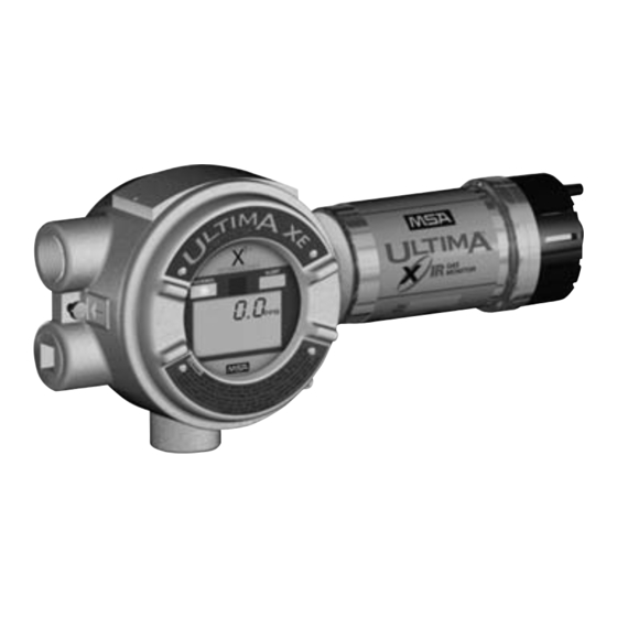
Page 15: Figure 1-3. Explosion-Proof Ultima Xir Monitor
The Ultima XE Gas Monitor is housed in a 316 stainless steel explosion-proof enclosure (FIGURE 1-2 shows the Ultima XE with the optional explosion-proof HART port). Figure 1-2. Explosion-Proof Ultima XE Monitor The Ultima XIR Gas Monitor is housed in a 316 stainless steel explosion-proof enclosure (FIGURE 1-3). -
Page 16: Figure 1-4. General-Purpose Xa Remote Sensor Module
Figure 1-4. General-Purpose XA Remote Sensor Module Figure 1-5. Explosion-Proof XE Remote Sensor Module... -
Page 17: Figure 1-6. Explosion-Proof Xir Remote Sensor Module
Figure 1-6. Explosion-Proof XIR Remote Sensor Module To determine your sensor type and options, check the shipping carton. Checked items are included in the carton. The carton label identifies: • Type of unit supplied (Gas Monitor, Gas Monitor Less Sensor, or Remote Sensor Module) •... -
Page 18: Installing Your Gas Monitor
Install the Ultima X Series Gas Monitors or the remote sensing module at a high level (ceiling) or low level (floor), depending on the density of the gas most likely to be found. -
Page 19: Installing The Ultima Xa Gas Monitor
The general-purpose Ultima X Series Gas Monitors can be a source of ignition and must not be mounted in an area where a flammable mixture of combustible gas and air may become present;... -
Page 20: Figure 1-7. Ultima Xe And Xir Mounting Bracket
Figure 1-7. Ultima XE and XIR Mounting Bracket... -
Page 21: Installing The Ultima Xir Gas Monitor
Installing the Ultima XIR Gas Monitor " WARNING The Ultima XIR Gas Monitor contains no user- or field-serv- iceable parts and must be returned to the factory for repair. Any attempt to open the monitor will damage the unit and void the warranty. -
Page 22: Electrical Connections For Ultima X Gas Monitors
See FIGURE 1-9 for location of grounding terminals. Figure 1-9. Ultima XE Grounding Terminals NOTE: For Ultima X Series units with internal relays, see Appendix A. This assembly is marked to identify power, ground and signal connections. -
Page 23: Wiring For All Models
Use caution when selecting a cable size. TABLE 1-2 expresses the maximum cable length when only using the Ultima X Series Gas Monitors. Ultima X Series options may take additional power which requires a heavier cable or a short cable run. Cable distances for units with internal relays are specified in Appendix A, TABLE A-1. -
Page 24: Table 1-2. Cable Length And Wire Size For Units Without
"Specifications"). All connections should be made by following appropriate wire code procedures. For proper installation of an AC power supply used with an Ultima X Series transmitter, refer to the following drawings for detailed information. Optional 12 VDC or 24 VDC internal and external power supplies can be ordered with the Ultima X Series Gas Monitors. -
Page 25: Use Of External Controllers
" WARNING When using any of the the Ultima X Series accessories (such as relays) with the 4 to 20 mA output Ultima X Series Gas Monitor, a three-wire connection must be used. Failure to use a three-wire connection could damage the electronics within the Ultima X Series Gas Monitor which can result in serious personal injury or loss of life. -
Page 26: Identify Pcb Configuration
Identify PCB Configuration • Identify the main pc board as a two-wire or a three-wire unit: • For XA Gas Monitors: while looking at the main pc board, locate the identifying label on the underside of the lid: • A-ULTX-PCB-A-1 is a two-wire unit, 4-20 mA output •... -
Page 27: Figure 1-10. General-Purpose Two-Wire Operation
• Two-wire 4 to 20 mA Ultima X Series Monitors operate in the current loop mode (FIGURE 1-10 for general-purpose) (FIGURE1-11 for explosion-proof). Figure 1-10. General-Purpose Two-Wire Operation Figure 1-11. Explosion-Proof Two-Wire Operation 1-14... -
Page 28: Figure 1-12. General-Purpose Three-Wire Operation
• Three-wire Ultima X Series Monitors operate in the current source mode (see FIGURE 1-12 for general-purpose) (FIGURE 1-13 for explosion-proof). Figure 1-12. General-Purpose Three-Wire Operation Figure 1-13. Explosion-Proof Three-Wire Operation 1-15... -
Page 29: Figure 1-14. Two-Wire Printed Circuit Board
Figure 1-14. Two-Wire Printed Circuit Board (no HART Protocol) Installation of Two-Wire, 4-20 mA Output (no HART Protocol) 1. Connect 8-30 VDC power lead to J8-1 (see FIGURE 1-14) 2. Connect J8-2 to the 4-20 mA output on the remote system. 3. - Page 30 Figure 1-15. Two-Wire Printed Circuit Board (with HART Protocol) Installation of Two-Wire, 4-20 mA Output with HART Protocol 1. Connect 12-30 VDC power lead to J8-1 (see FIGURE 1-15). NOTE: The HART signal is not available below 12 VDC on the two-wire pc board. 2.
-
Page 31: Figure 1-16. Three-Wire Printed Circuit Board
Figure 1-16. Three-Wire Printed Circuit Board (no HART Protocol) Installation of Three-Wire, 4-20 mA Output (no HART Protocol) 1. Connect 8-30 VDC power lead to J8-1 (see FIGURE 1-16) 2. Connect J8-2 to the 4-20 mA output on the remote system. 3. - Page 32 Figure 1-17. Three-Wire Printed Circuit Board (with HART Protocol) Installation of Three-Wire, 4-20 mA Output with HART Protocol 1. Connect 8-30 VDC power lead to J8-1 (see FIGURE 1-17) 2. Connect J8-2 to the 4-20 mA input on the remote system. 3.
-
Page 33: Installing The Ultima X Remote Sensor Module
The Remote Sensor Module is used with the Ultima X Gas Monitor for installations requiring remote placement of the gas sensor. FIGURES 1-18 and 1-19 show the general-purpose and explosion-proof configurations. Figure 1-18. Remote Module General-Purpose Ultima X Series Wiring Figure 1-19. Remote Module Explosion-Proof Ultima X Series Wiring 1-20... -
Page 34: Electrical Connections For Remote Sensors
Five conductors are required for the Ultima XE and Ultima XA Remote Sensor Modules. Four conductors are required for the Ultima XIR Remote Sensor Module. The Ultima X Series Monitor has a five-wire terminal to accommodate up to #16 AWG conductors. For wiring details, see the applicable Installation Outline Drawing listed in TABLE 1-1. -
Page 35: Table 1-4. Remote Module Wiring And Placement
5 cond., shielded, 14 AWG At the Ultima X Series Remote Sensor Location: 1. Open the Ultima X Series Remote Sensor cover by removing lid. 2. For the Ultima XA Gas Monitor, route the power and signal cable from the Gas Monitor through a customer-created opening in the enclosure and wire it to the appropriately labeled connection on the terminal block (FIGURE 1-4). - Page 36 NOTES: Grounding • Incoming power and signal cable shield should be earth grounded at the power source. • Connect power and remote sensor cable shields to shield terminals on main pc board. • Provide shield terminations inside the sensor housing as indicated on Installation Outline Drawings for Remote Sensor.
-
Page 37: Start-Up And Calibration
• During the 30-second countdown, the output signal is the same as the calibration signal when enabled during a normal calibration. This is described later in this chapter under "Ultima X Series Gas Monitor Calibration Output Signal". • For units with LEDs, the Alert red LED will be solid ON during the 30-second countdown. -
Page 38: Table 2-1. Instrument Operation
Ultima X Series Gas Monitors will display one of two modes: • +LOC % LEL - The Ultima X Series Gas Monitor has been exposed to a high concentration of gas (above the LEL) and it is possible that the over-range condition may still exist. - Page 39 OPERATION LEDs 4 to 20 mA FAULT RELAY GREEN RED NORMAL Gas value Energized steady ALARMING Flashing Gas value Energized FAULT 3.0 mA De-energized steady POWER <3.75 mA De-energized UP (HART steady Version) POWER <3.1 mA De-energized steady (Non-HART Version) COUNT ON steady ALERT option disabled;...
-
Page 40: Calibration Basics
Calibration Basics While the Ultima X Series Gas Monitor is factory-calibrated, it is good practice to calibrate the unit once it is installed in its final environmental destination. As with any type of gas monitor, the only true check of its performance is to apply gas directly to the sensor. -
Page 41: Figure 2-2. Ultima Calibrator
• HART ® -compatible communications interface with Device Description Language capability (DDL) or generic HART interface with Manufacturer Specific Command capability. This hand-held HART Communicator must be HART revision 7 compliant and can be obtained from a HART-authorized supplier. See Appendix D for command definitions. -
Page 42: Ultima Calibrator
Changing of full scale value. NOTE: See Ultima Controller/Calibrator manual (P/N 813379) for full functionality. NOTE: When an Ultima X Series Gas Monitor has an active latched alarm (indicated by a flashing alarm display): • An infrared (IR) remote device (such as the Ultima Calibrator or Controller) may be used to reset this alarm. -
Page 43: Calibration Kit
• Due to the unstable nature of Chlorine Dioxide (ClO 2 ), Chlorine gas is used as a calibration simulant. If using the MSA calibration system and gas cylinder (P/N 710331), the response ratio is 2:1. In other words, the 2 ppm sample of Chlorine should be set to read 1 ppm of ClO 2 . -
Page 44: Equipment Required
Equipment Required Three calibration kits (numbered 40, 41, and 54) are available from MSA for diffusion Ultima X Series Gas Monitors. Kit 40, 41, and 54 are housed in a convenient carrying case and contain all items necessary (less gas) for a complete and accurate calibration. -
Page 45: Span Gas Values
Span Gas Values The Ultima X Series Gas Monitor is factory-shipped with a preset span gas value (TABLE 2-2). This span gas value can be changed via the Ultima Controller or a HART controller; otherwise, the span gas must correspond to preset concentrations. - Page 46 GAS TYPE RANGE SPAN GAS WARM-UP PRESET CYLINDER TIME VALUES CHLORINE 0-5 PPM 2 PPM 710331 30 minutes 0-10 PPM 2 PPM 30 minutes 0-20 PPM 10 PPM 10028066 30 minutes HYDROGEN 0-50 PPM 10 PPM 10028072 30 minutes CYANIDE HYDROGEN 0-10 PPM 8 PPM...
-
Page 47: Table 2-3. Calibration Guide For Combustible Gas Sensor
Table 2-3. Calibration Guide for Combustible Gas Sensor CATEGORY 31: FOR CATALYTIC TYPE 1S NATURAL GAS To detect the following gases, recalibrate with 0.6% propane & set span gas value accordingly Acetaldehyde Hydrogen Acetylene MAPP Gas Butadiene, 1, 3 Methane Carbon Monoxide Methanol Ethane... -
Page 48: Initial Calibration
CATEGORY 38: ULTIMA XIR METHANE To detect the following gases, recalibrate with 2.5% methane & set span gas value accordingly Methane CATEGORY 39: ULTIMA XIR NON-METHANE To detect non-methane gases, recalibrate with stated % propane & set span gas value as given in Appendix B For additional gases for the Ultima XIR, see Appendix B. -
Page 49: Standard Calibration
Turn on zero gas flow by turning knob on the flow controller. 3. Point the Calibrator or Controller at the Ultima X Series Monitor display; press the CALIBRATE button. NOTE: The zero or calibration process can be aborted at anytime during the 30-second countdown interval;... -
Page 50: Figure 2-5. Apply Zero Gas Flag
If CAL FAULT appears on the display, this indicates: • An unsuccessful attempt to zero or calibrate the Ultima X Series Monitor • The Ultima X Series Monitor is operating with the calibration parameters defined before the calibration was attempted. 2-14... -
Page 51: Figure 2-6. Apply Span Gas Flag
"span" sequence as described in the following section. Spanning 5. During a regular calibration, the Ultima X Series Gas Monitor automatically begins the span countdown after a successful zeroing of the unit. The span countdown is 30 seconds (FIGURE 2-6). - Page 52 Ensure that any calibration gases are applied during the 30- second count down period. • If a CAL FAULT indication is on the Ultima X Series Gas Monitor display before the user is able to apply the gas, a steady state gas condition was reached, causing the unit to use a wrong reading as a span indication.
-
Page 53: Figure 2-7. Calibration End Display
To extinguish the CAL FAULT flag, a complete calibration procedure must be performed. The Ultima X Series Gas Monitor allows automatic zero and span adjustments within a pre-defined range. It cannot make corrections outside this range, such as when an empty or wrong cylinder of gas is applied or failure to begin gas flow within the allotted 30- second countdown occurs. -
Page 54: Oxygen Calibration
No calibration cap or zero gas is necessary. To meet the specification stated, it is necessary to span the oxygen Ultima/Ultima X Series Gas Monitor with the Calibration Kit and an oxygen cylinder. The concentration of oxygen in air varies slightly due to changing relative humidity and pressure levels. - Page 55 Calibration Documentation The Ultima X Series Monitor records the date of the last successful calibration. This date can then be displayed on the front-panel LCD (with the use of the Controller or via the HART Controller).
-
Page 56: Chapter 3, Specifications
Chapter 3, Specifications Table 3-1. Performance Specifications GAS TYPES Combustibles, Oxygen & Toxics TEMPERATURE TOXICS & OPERATING 0 to 40°C (32 to +104°F) RANGE OXYGEN RANGE *EXTENDED -20 to +50°C (-4 to +122°F) RANGE OPERATING 0 to +30°C (32 to +86°F) RANGE NH 3 *EXTENDED -10 to +40°C (+14 to +104°F) - Page 57 ACCURACY LINEARITY REPEATABILITY CARBON MONOXIDE +2% FS +1% FS or 2 ppm OXYGEN +2% FS +1% FS HYDROGEN SULFIDE +10% FS or 2 ppm +1% FS or 2 ppm CHLORINE +10% FS or 2 ppm +5% FS or 1 ppm SULFUR DIOXIDE +10% FS or 2 ppm...
- Page 58 COMBUSTIBLES OXYGEN & TOXICS 2 years, typically AMMONIA FULL REPLACEMENT 1 year from installation; 10 years for IR WARRANTY Sensor source (see "MSA Instrument Warranty" in this manual for complete details) WIRING OXYGEN 2-wire or 3-wire REQUIRE- & TOXICS MENTS...
-
Page 59: Table 3-2. Sensor Response To Interferants
POWER CON- OXYGEN & TOXICS 8 VDC 250 mA max SUMPTION * 12 VDC 175 mA max (TOTAL UNIT 24 VDC 100 mA max WITH RELAYS) CATALYTIC 8 VDC 600 mA max COMBUSTIBLES 12 VDC 400 mA max 24 VDC 210 mA max IR COMBUSTIBLES 8 VDC... - Page 60 ND = No Data INTER- CONCEN- CO H 2 S Cl 2 SO 2 NO 2 FERANT TRATION filtered filtered (PPM) Acetone 1000 Acetylene 12000 Ammonia Arsine Benzene Bromine Carbon Dioxide 5000 Carbon Disulfide Carbon Monoxide Chlorine -0.2 Diborane Ethylene -0.3 Ethyl Alcohol...
- Page 61 ND = No Data INTER- CONCEN- ClO 2 PH 3 ASH 4 SiH 4 GeH 3 B 2 H 6 Br 2 FERANT TRATION (PPM) Acetone 1000 Acetylene 12000 Ammonia Arsine Benzene Bromine Carbon Dioxide 5000 Carbon Disulfide Carbon Monoxide Chlorine Diborane Ethylene...
- Page 62 ND = No Data INTER- CONCEN- NH 3 FERANT TRATION (PPM) Acetone 1000 Acetylene 12000 Ammonia Arsine Benzene Bromine Carbon Dioxide 5000 Carbon Disulfide Carbon Monoxide Chlorine Diborane Ethylene Ethyl Alcohol Ethylene Oxide Ether Fluorine Freon 12 1000 Germane Hexane Hydrogen Hydrogen Chloride...
-
Page 63: Chapter 4, Maintenance
Chapter 4, Maintenance General The Ultima X Gas Monitor is constantly performing a self-check. When a problem is found, it displays the appropriate error message (TABLE 4-3, "Troubleshooting Guidelines"). When a critical error is detected within the unit, the 4-20 mA output signal goes to a fault condition of 3.0 mA The "Sensor Warning"... -
Page 64: Table 4-2. Configuration Display Messages
Table 4-2. Configuration Display Messages MESSAGE INDICATES CAL SIG ON Instrument will output the calibration signal during calibration CAL SIG OFF Instrument will output gas value during calibration LTCH/ Latching relay operations UNLTCH/ Non-latching relay operations INCR/ Increasing Alarm relay operations DECR/ Decreasing Alarm relay operations ENER... - Page 65 MN SUPPLY Power supply on main PCBA Check sensor wiring FAULT is out of range or replace main pc board RELAY Error with the internal relays Cycle power to the unit FAULT has occurred or replace main pc board SNSR POWER Power at the sensor module Correct wiring error, replace main FAULT...
-
Page 66: Ultima Xir Cleaning Procedure
Ultima XIR Cleaning Procedure The presence of particulate matter, oil films, liquid water, or the residue from water drops on the two monitor windows can adversely affect its performance. The environmental guard is designed to prevent foreign solids or liquids from reaching the monitor's optical system. Additionally, heating elements are incorporated into the unit to prevent water condensation. -
Page 67: Replacing An Ultima Xe Or Ultima Xa Sensor
Replacing an Ultima XE or Ultima XA Sensor The only routine maintenance item is the sensing element itself, which has a limited lifetime. When the Ultima X Series Gas Monitor's read-out indicates that the sensor must be changed, there is very little sensor lifetime remaining. -
Page 68: Figure 4-1. "Change Sensor" Scrolls Across The Display
MSA at the address given under "Obtaining Replacement Parts." 1. There is no need to open the main enclosure; simply unscrew the sensor assembly located on the bottom of the Ultima X Series Gas Monitor main assembly (FIGURE 4-2). " WARNING... -
Page 69: Figure 4-2. Sensor Assembly And Sensor Guard For General-Purpose Model
(e.g., carbon monoxide to oxygen). 3. The Ultima X Series Gas Monitor is shipped with the Sensor Swap Delay enabled. This means that the 4-20 mA output signal and the FAULT relay will hold off a fault indication for 60 seconds after the sensor missing indication is displayed on the instrument. -
Page 70: Obtaining Replacement Parts
Mine Safety Appliances Company 1000 Cranberry Woods Drive Cranberry Township, PA 16066 or call, toll-free, 1-800-MSA-INST. Inquiries can also be e-mailed to customer.service@msanet.com. " WARNING Use only genuine MSA replacement parts when performing any maintenance procedures provided in this manual. - Page 71 GAS SELECTION SENSOR KIT PART NO. GENERAL- EXPLOSION- GENERAL- PURPOSE PROOF PURPOSE PLASTIC MODEL E STAINLESS MODEL A MODEL G Hydrogen Chloride, 50 ppm A-ULTX-SENS-23-0... not available A-ULTX-SENS-23-6... Chlorine Dioxide, 3 ppm A-ULTX-SENS-24-0... not available A-ULTX-SENS-24-6... Combustible Gas, 100% LEL A-ULTX-SENS-31-0...
-
Page 72: Appendix A, Optional Features
(if the Delay feature is enabled). Unpacking, Mounting and Wiring Unpack, mount and wire the Ultima X Series Gas Monitor according to Chapter 1, "Installation". All electrical connections to the Ultima X Series Gas Monitor can be made via the clearly marked board-mounted... -
Page 73: Ultima X Series Gas Monitor Internal Relays
See Ultima Controller and Calibrator Manual (P/N 813379) for complete relay configuration information. Power cable wiring lengths for the Ultima X Series Gas Monitor with internal relays differ from models without internal relays (TABLE A-1). Table A-1. Cable Length and Wire Size for Units... -
Page 74: Alarm Relays
Alarm Relays There are three alarm relays and one fault relay in the Ultima X Series Gas Monitors. The three alarm relays: • Activate when the Monitor detects a gas concentration level that exceeds setpoints • Alarms 1, 2 and 3 generally default to 10%, 20% and 30% of the full-scale reading and are set when the gas reading is above these values. -
Page 75: Fault Relay Or Trouble
PLC or DCS connected to the fault relay: • Fault Relay STEADY ON indicates: • Ultima X Series sensor is not connected properly or • Ultima X Series Gas Monitor internal fault or • An inoperative relay. -
Page 76: Relay Connections
• Fault Relay PULSED (once per minute) indicates: • Improper calibration of the Ultima X Series Gas Monitor or • Ultima X Series Gas Monitor CHECK CAL or CAL FAULT displayed. Relay Connections All electrical connections to internal relays can be made directly on the pc board (see FIGURE A-1). -
Page 77: Figure A-2. Relay Printed Circuit Board
7. Pull the cable away from the unit to relieve any excess slack. • It is important not to have excess wire or cable within the module to avoid unwanted AC noise. 8. Re-install the cover of the Ultima X Series Gas Monitor. -
Page 78: Optional Reset Push-Button
2) Optional RESET Push-button • If you are going to specify a switch to use with the Ultima X series, it should have, as a minimum, an equivalent (or better) approvals classification. The MSA provided pushbutton (P/N 10046923) is explosion-proof for Class I, Groups B, C, and D only. When relied... -
Page 79: Optional Push-Button Calibration
• The RESET push-button must be a normally-open type with a momentary contact when pushed. • The electrical ratings must be at least 1 amp at 250 volts AC. • Specific push-buttons may be sourced by manufacturers such as Appleton Electric and Crouse Hindes, Inc. Optional Push-button Calibration The following procedure is used to enter the calibration by using the push-button. -
Page 80: Optional Horn Relay Software
3) Optional Horn Relay Software The Ultima X Series Gas Monitor is available with optional Horn Relay Software to allow an audible horn to be used with Relay 1. The following describes the use and functionality of this optional feature. -
Page 81: Calibration Guide For Additional Xir/Xi Gases
Appendix B, Calibration Guide for Additional XIR/XI Gases... -
Page 83: General Certification Information
Appendix C, General Certification Information... -
Page 85: Hart Specific Information
Appendix D, HART Specific Information HART Field Device Specification The Ultima X Series Gas Monitor is available with an optional HART (Highway Addressable Remote Transducer) output communications protocol. With this option, the Ultima X Series Gas Monitor complies with HART Protocol Revision 7 and uses the 16-bit manufacturer and device codes. -
Page 86: Host Interface
Host Interface Analog Output The three-wire 4-20 mA current loop is connected on terminals marked 8-30 VDC(1), 4-20 mA OUT(2), and GND (3-wire)(3). The two-wire 4-20 mA current loop is connected on the 8-30 VDC(1) and 4-20 mA OUT(2) terminals. Refer to the installation outline drawings shown in Chapter 1, TABLE 1-1 for details. -
Page 87: Status Information
Table D-3. Device Variables Exposed by the Ultima Monitor VARIABLE DESCRIPTION VARIABLE DESCRIPTION Gas Type Sensor gas type description Last Cal Date Date sensor was last calibrated Alarm Gas value at which an Auto Zero comp Amount of compensated Setpoints alarm status bit is set below zero drift Alarm Action... -
Page 88: Table D-5. Additional Device Status (Command #48
Table D-5. Additional Device Status (Command #48) Command #48 returns 5 bytes of data, with the following status information: BYTE MEANING CLASS DEVICE STATUS BITS SET Configuration Reset Error Main ram fault Error Main flash fault Error EEprom write error Error Incompatible sensor Error... - Page 89 BYTE MEANING CLASS DEVICE STATUS BITS SET End of Life Warning Warning Sensor Swap Delay Info Change Sensor Fault Error Sensor Power Fault Error Internal Comm Fault Error Cal Sig Enable Info Alert Option Enable Info Relay Fault Error Alarm 1 Set Warning Alarm 2 Set Warning...
-
Page 90: Universal Commands
Universal Commands All Universal commands have been implemented in the Ultima Gas Monitor. The Ultima Gas Monitor returns a 7 in the Universal rev to indicate the device is using the expanded 16-bit manufacturer and device codes. Common-Practice Commands The following Common Practice commands have been implemented in the Ultima X device: Table D-6. -
Page 91: Command #129: Read Sensor Gas Type
Table D-7. Device-Specific Commands The following device-specific commands are implemented in the Ultima Monitor: COMMAND # DESCRIPTION Read Sensor Gas Type Read Device RTC Read Alarm Setpoints Read Alarm Control Actions Read Min/Max/Average Values Read Last Cal Date Read Gas Table Read Input Voltage Read Auto Zero Comp Read Sensor Status... -
Page 92: Command #130: Read Device Real Time Clock
Request Data Bytes None. Response Data Bytes BYTE FORMAT DESCRIPTION ASCII Sensor gas type description (see TABLE D-8) Command #130: Read Device Real Time Clock Reads the Real Time clock hours and minutes from the Ultima X Gas Monitor. Request Data Bytes None. -
Page 93: Command #132: Read Alarm Control Actions
Command #132: Read Alarm Control Actions Reads the Ultima X Alarm Control Actions. Request Data Bytes None. Response Data Bytes BYTE FORMAT DESCRIPTION Bit Enum Alarm 1 Control Actions (see TABLE D-9) Bit Enum Alarm 2 Control Actions (see TABLE D-9) Bit Enum Alarm 3 Control Actions (see TABLE D-9) Command #133: Read Min, Max, Avg Values... -
Page 94: Command #134: Read Last Cal Date
Command #134: Read Last Cal Date Returns the Ultima last calibration date of the currently connected sensor. Request Data Bytes None. Response Data Bytes BYTE FORMAT DESCRIPTION Unsigned Last sensor calibration date Command #135: Read Gas Table This command returns the Ultima sensor Gas Table currently in use. The Gas Tables are linearization reference tables used with certain sensors to provide accurate response for different gases from the same sensor. -
Page 95: Command #137: Read Auto Zero Comp Value
Command #137: Read Auto Zero Comp Value Returns the Ultima Automatic Zero Compensation value. This value is accumulated by the device when the sensor reading attempts to drift below zero. This value is used to compensate the actual Zero calibration. The device will attempt to compensate up to 10 counts (display units) before setting the under-range bit. -
Page 96: Command #141: Read Cal Signal Status
Command #141: Read Cal Signal Status This command returns the Ultima X Cal Signal status. This is a single byte containing a 0 if disabled or 1 if enabled. If enabled, the output will be set to 3.75 mA during calibration (21 mA for oxygen). If disabled, the output will track the gas concentration. -
Page 97: Command #143: Read Sensor Temperature
Command #143: Read Sensor Temperature This command returns the Ultima X Sensor Temperature. This is a single byte containing an integer value representing the temperature returned by the gas sensor. Not all gas sensors have an on-board temperature. Request Data Bytes BYTE FORMAT DESCRIPTION... -
Page 98: Command #173: Write Rtc
Command #173: Write RTC Writes the Ultima Real Time Clock hours and minutes values.The real time clock is used to compute the minimum, maximum and average values and to date stamp the last sensor calibration date. Request Data Bytes BYTE FORMAT DESCRIPTION Unsigned... -
Page 99: Command #174: Write Alarm Setpoints
Command #174: Write Alarm Setpoints Writes the Ultima Alarm Setpoint values. The Ultima Gas Monitor uses alarm setpoint values to set alarm status bits in the device. The alarms can be enabled or disabled, set to increasing or decreasing and can be set to latching (see "Command 175: Write Alarm Setpoint Control Actions"). -
Page 100: Command #175: Write Alarm Setpoint Control Actions
Command #175: Write Alarm Setpoint Control Actions Writes the Ultima X Alarm Setpoint Control Actions. The Ultima X Gas Monitor uses alarm setpoint Control Actions to enabled or disabled, set to increasing or decreasing and to set the alarm to latching or non latching. -
Page 101: Command #176: Write Average Interval
Command #176: Write Average Interval Writes the Ultima Average Interval. This interval is in hours and is used by the device to determine the collection interval for Minimum, Maximum and Average values. The Average collection interval can be for 1, 8 or 24 hours. Request Data Bytes BYTE FORMAT... -
Page 102: Command #177: Write Upper Trim Point
Command #177: Write Upper Trim Point Writes the Ultima X Upper Trim or Span point value. The Ultima Gas Monitor uses the Upper trim point value to perform Span calibration. When a Span calibration is performed, the device automatically sets the highest reading obtained to this Span value. -
Page 103: Command #178: Write Gas Table
Command #178: Write Gas Table Writes the Ultima X Gas Table selection. The Ultima Gas Monitor uses the Gas Table value to select a reference table of linearization values for certain sensors. Request Data Bytes BYTE FORMAT DESCRIPTION Unsigned Gas Table selection number (see TABLE D-10) Response Data Bytes BYTE FORMAT... -
Page 104: Command #179: Write Sensor Data Sheet
Command #179: Write Sensor Data Sheet Reset Control Writes a data sheet reset command to Ultima X Gas Monitor. This command causes the Ultima Monitor to reset the current sensor data sheet to factory default settings. This command will set certain device warning status bits and require the user to re-calibrate the sensor. -
Page 105: Command #180: Write Sensor Swap Delay Enable
Command #180: Write Sensor Swap Delay Enable This command writes command number to the Ultima X Gas Monitor to enable or disable the two-minute swap delay feature. This device feature enables a two-minute hold-off of the sensor missing fault, allowing the user to “Swap” or change sensor modules without having the 4-20 mA set to the fault condition. -
Page 106: Command #181: Write Cal Signal Enable
Command #181: Write Cal Signal Enable This command writes command number to the Ultima X Gas Monitor to enable or disable the Cal signal output. Without the Cal Signal enabled, the 4-20 mA output will follow the gas reading during calibration. With the Cal Signal enabled, the 4-20 mA output will be set to 3.75 ma during calibration and be held there for one minute after calibration has ended to allow the sensor to re-stabilize. -
Page 107: Command #182: Write Calibration Mode
Command #182: Write Calibration Mode This command writes a calibration mode number to the Ultima Gas Monitor. The mode commands initiate a calibration sequence in the device. Device status byte 2 can be monitored to determine the progress of the calibration. Request Data Bytes BYTE FORMAT... -
Page 108: Command #183: Write Calibration Abort
Command #183: Write Calibration Abort This command writes a calibration Abort command to the Ultima Gas Monitor. The calibration abort command instructs the device to suspend the calibration sequence initiated by the calibration mode command. Valid number for this command is 1. Request Data Bytes BYTE FORMAT... -
Page 109: Command #184: Write Calibration Step
Command #184: Write Calibration Step This command writes a calibration Step Command to the Ultima Gas Monitor. The Step command instructs the device to advance to the next step during a manual calibration sequence. Device status byte 2 can be monitored to determine the progress of the calibration. -
Page 110: Command #185: Write Alarm Acknowledge
Command #185: Write Alarm Acknowledge This command writes an Alarm Acknowledge command to the Ultima X Gas Monitor. The alarm acknowledge command instructs the device to clear any latched alarms in the device, provided the setpoint level for the alarm has receded. Valid command number is on 1. Request Data Bytes BYTE FORMAT... -
Page 111: Command #186: Write Protect Mode
Command #186: Write Protect Mode This command sends a single, unsigned byte to the device. Sending a one puts the device in write protect mode. In write protect mode, all writes and commands are ignored except a command to disable the write protect. -
Page 112: Command #187: Write Alert Option
Command #187: Write Alert Option This command disables or enables the Alert Option on the Ultima X unit. This is a single byte containing a 0 if disabled or 1 if enabled. If enabled, the Alert Option will cause the 4-20 mA to be set to 3.75 mA during calibration of an Oxygen sensor (if the Cal Signal Option is also enabled). -
Page 113: Command #188: Write Relay Normal State
Command #188: Write Relay Normal State This command sets the Ultima X Normal relay state. This is a single byte containing a bit map of the three alarm relays’ non alarm states. Not all gas sensors have on-board relays. Request Data Bytes BYTE FORMAT DESCRIPTION... -
Page 114: Table D-8. Gas Type Descriptions
Table D-8. Gas Type Descriptions GAS TYPE DESCRIPTION GAS TYPE DESCRIPTION Carbon Monoxide Performance verified to ANSI/ISA-92.00.01 by FM Approvals Oxygen COMB Combustible-pellistor XiIR Infrared Combustible H 2 S Hydrogen Sulfide Performance verified to ANSI/ISA-92.00.01 by FM Approvals Chlorine Cl 2 Chlorine Dioxide NH 3 Ammonia... -
Page 115: Table D-11. Calibration Modes
Table D-11. Calibration Modes MODE # DESCRIPTION Initiate Zero Sensor sequence Initiate Standard calibration sequence Initiate Initial calibration sequence Initiate Manual (stepped) calibration sequence Table D-12. Sensor Status Codes CODE DESCRIPTION 0x01 Flash Fault 0x05 Ram Fault 0x07 Pellement Fault 0x0A Data Sheet Fault 0x1E... -
Page 116: Performance
Performance Typical sampling rates are shown in the following table. Table D-13. Sampling Rates Gas Samples 4 per second PV digital value calculation 5 per second Analog output update 5 per second Power-Up On power-up, the transmitter goes through a self-test procedure (see Chapter 2, "Initial Start-up"), and a sensor warm up and initialization period which takes approximately 30 seconds. -
Page 117: Busy And Delayed-Response
• Program ROM • Configuration storage EEPROM • Sensor communications • Data sheet integrity • Internal communications. This self-test takes about 10 seconds. During self-test, following power- up or reset, the analog output is set to 3.75 mA and the device does not respond to HART commands. -
Page 118: Modes
Damping is internally-fixed, affecting only the PV and the loop current signal. There is no user-settable damping control. Capability Checklist Table D-15. Capability Checklist Manufacturer, model and revision MSA , Ultima, rev. 2 Device type Transmitter HART revision Device Description available... -
Page 119: Default Configuration
Default Configuration Table D-16. Default Configuration PARAMETER DEFAULT VALUE Lower Range Value Upper Range Value Sensor dependent PV Units Sensor dependent Sensor type various Number of wires Damping time constant Fault-indication jumper Sensor dependent Write-protect mode write enabled Number of response preambles Alarms Enabled ®... - Page 120 the “Sensor Zero” function and acknowledge the screen. See FIGURE D-11 for a view of this screen. Calibration initiated screen Once a calibration selection function is selected, the command is sent to the device. A status messages is then returned to indicate the progress.
-
Page 121: Standard Zero/Span Calibration Selection Menu
Calibration gas reminder screen Once the device has performed a successful Zero function and stored the calibration information, it returns a calibration OK message. This causes a series of calibration closure messages to appear. The first closure message is a reminder to disconnect any calibration gases from the device. - Page 122 Calibration initiated screen Once a calibration selection function is selected, the command is sent to the device. A status message is then returned to indicate the progress. The first status message should indicate that the calibration sequence has started. This screen also shows the sensor value, units and type information.
- Page 123 countdown wait for gas connection and transport. The user is prompted to start applying the Span calibration gas at this time. (For a 0-25% Oxygen sensor, the sensor can be spanned using room air.) See FIGURE D-14 for a sample view of this screen. The red LED is ON solid and the green LED is blinking on the main board to indicate the start of the Span procedure.
-
Page 124: Initial Calibration Procedures
Initial Calibration Procedures Initial Calibration Selection Menu Initial calibration is selected in a manner similar to the standard Zero/Span calibration procedure and the steps are similar (except the function selection should be “Initial Cal”). Initial calibration should be run when a new sensor is connected to the unit or when a standard Zero/Span procedure will not clear a fault condition (such as when the wrong Span gas is used). -
Page 125: Figure D-1. Zero Cal Step Screen
Zero cal step screen Figure D-1. Zero cal step screen Span cal step screen Figure D-2. Span cal step screen D-41... -
Page 126: Figure D-3. Select Sensor Calibration
Sample Calibration Display Screens HART DDL-based calibration display screens Select Sensor Calibration from the Sensor Trim Menu Figure D-3. Select Sensor Calibration from the Sensor Trim Menu D-42... -
Page 127: Figure D-4. First Warning Screen
First warning screen Figure D-4. First Warning screen D-43... -
Page 128: Figure D-5. Second Warning Screen
Second warning screen Figure D-5. Second Warning screen D-44... -
Page 129: Figure D-6. Standard Calibration Function Select Screen
Standard Calibration function select screen Figure D-6. Standard Calibration function select screen D-45... -
Page 130: Figure D-7. Calibration Initiated Screen
Calibration initiated screen Figure D-7. Calibration initiated screen D-46... -
Page 131: Figure D-8. Selection Confirmation Screen
Selection Confirmation Screen Figure D-8. Selection Confirmation screen D-47... -
Page 132: Figure D-9. Sensor Zero Countdown Screen
Sensor Zero Countdown screen Figure D-9. Sensor Zero Countdown screen D-48... -
Page 133: Figure D-10. Zero Adjustment Screen
Zero Adjustment screen Figure D-10. Zero Adjustment screen D-49... -
Page 134: Figure D-11. Span Countdown Screen
Span countdown screen Figure D-11. Span Countdown screen D-50... -
Page 135: Figure D-12. Adjusting Span Screen
Adjusting Span screen Figure D-12. Adjusting Span screen D-51... -
Page 136: Figure D-13. Calibration Completion Message
Calibration completion message Figure D-13. Calibration Completion message D-52... -
Page 137: Figure D-14. Calibration Gas Reminder Screen
Calibration gas reminder screen Figure D-14. Calibration Gas Reminder screen D-53... -
Page 138: Figure D-15. Loop Control Reminder Message
Loop control reminder message Figure D-15. Loop Control Reminder message Troubleshooting Fault indications Span Fault This fault can occur if the sensor is in cal mode and the required SPAN gas is not applied to the sensor at the indicated time or within the timeout period. -
Page 139: Figure D-16. Calibration Status Screen
Span faults can also be caused by a bad sensor, sensor at end-of-life, or a sensor that is too far out of calibration for the Standard Zero/ Span procedure to make the adjustment. An attempt to Initial Cal the sensor may be able to correct the calibration;... -
Page 140: Figure D-17. Sensor Trim Point Screen
Sensor trim point screen Figure D-17. Sensor Trim Point screen D-56... -
Page 141: Figure D-18. Additional Sensor Status Screen
Additional Sensor status screen Figure D-18. Additional Sensor Status screen Zero Fault The Zero Fault can be caused by a faulty sensor, calibration out of the Standard Zero/Span calibration range, sensor in change, sensor fault or attempting to zero the sensor with Span gas applied. The application of Zero gas should be checked and the sensor status (as defined in FIGURES D-16 and D-18) verified if this fault occurs. -
Page 142: Figure D-19. Device Status Screen
Calibration Aborted User calibration abort or sensor calibration faults can cause a calibration process to abort. Status group 2 as shown in FIGURE D-16 can be viewed to determine if the abort was caused by a cal fault. Status group 2 can be expanded by right-clicking the selection as shown in FIGURE D-19 to provide additional information (also see FIGURE D-16).
Need help?
Do you have a question about the Ultima X Series and is the answer not in the manual?
Questions and answers
where can I purchase an Ulltima X500 gas monitor? we have one that is no longer working and we need to replace it.