Table of Contents
Advertisement
Ultima
Series Controller
and Calibrator
Instruction Manual
THIS MANUAL MUST BE CAREFULLY READ BY ALL INDIVIDUALS WHO HAVE OR WILL
HAVE THE RESPONSIBILITY FOR USING OR SERVICING THE PRODUCT. Like any piece
of complex equipment, this instrument will perform as designed only if it is used and
serviced in accordance with the manufacturer's instructions. OTHERWISE, IT COULD
FAIL TO PERFORM AS DESIGNED AND PERSONS WHO RELY ON THIS PRODUCT FOR
THEIR SAFETY COULD SUSTAIN SEVERE PERSONAL INJURY OR DEATH.
The warranties made by Mine Safety Appliances Company with respect to the product
are voided if the product is not used and serviced in accordance with the instructions
in this manual. Please protect yourself and others by following them. We encourage
our customers to write or call regarding this equipment prior to use or for any additional
information relative to use or repairs.
IN the U.S., to contact your nearest stocking location, dial toll-free 1-800-MSA-INST.
To contact MSA International, dial1-412- 967-3354
© MINE SAFETY APPLIANCES COMPANY 2010 - All Rights Reserved
This manual is available on the internet at www.msanet.com
Manufactured by
MSA NORTH AMERICA
P.O. Box 427, Pittsburgh, Pennsylvania 15230
(L) Rev 12
®
/Ultima
" WARNING
®
X
813379
Advertisement
Table of Contents

Subscribe to Our Youtube Channel
Related Manuals for MSA Ultima Series


Summary of Contents for MSA Ultima Series
- Page 1 IN the U.S., to contact your nearest stocking location, dial toll-free 1-800-MSA-INST. To contact MSA International, dial1-412- 967-3354 ©...
- Page 2 MSA Permanent Instrument Warranty 1. Warranty- Seller warrants that this product will be free from mechanical defect or faulty workmanship for a period of two years from date of shipment, provided it is maintained and used in accordance with Seller's instructions and/or recommendations. This...
-
Page 3: Table Of Contents
Chapter 1, General Information ....1-1 Figure 1-1. Ultima Calibrator ....1-1 Three Function Operation . - Page 4 INITIAL Calibration ......2-10 Regular Calibration ......2-11 Zeroing .
- Page 5 To set the three levels of alarm: ....3-7 Setting the Three Ultima X Series Gas Monitor Alarm Setpoint Values ... . .3-8 To set the three levels of alarm: .
- Page 6 Procedure 17. Setting an Unused Sensor to the Disabled Mode . . .3-18 Procedure 18. Setting the MODBUS BAUD rate..3-19 Programming the Controller .....3-19 Removing Existing Programs .
-
Page 7: General Information
Chapter 1, General Information This manual describes the operation and use of the Ultima Controller and Ultima Calibrator for the Ultima Gas Monitor and the X Series Gas Monitors. It is strongly recommended that this entire manual be read before using the controller or the calibrator. The controller and calibrator use an Infrared (IR) LED to transmit to an IR receiver in the Ultima/Ultima X Series Gas Monitor. -
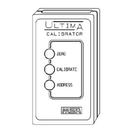
Page 8: Three Function Operation
Three Function Operation The Ultima Calibrator is equipped with three buttons for the following functions: 1. ZERO Button: • Performs a zero function on the Ultima/Ultima X Series Gas Monitor; periodically, the monitor may require only a zero adjustment. 2. CALIBRATE Button: •... -
Page 9: The Ultima/Ultima X Controller (Figure 1-3)
The Ultima/Ultima X Controller (FIGURE 1-3): Figure 1-3. Ultima/Ultima X Controller • Allows non intrusive calibration of an Ultima/Ultima X Series Gas Monitor, enabling the Monitor to be calibrated at the unit without opening the enclosure • Is a hand-held, self-contained unit powered by two internal AA batteries •... -
Page 10: Using The Id Code Feature
4. Enter 9999 and press the ENTER button. • The unit enters the READY mode and disables the password ID function for future operation. NOTE: If the ID password is set and forgotten, contact an MSA service representative. Turning the Controller ON Press the ENTER button. -
Page 11: Turning The Controller Off
• If unit displays the ID CODE prompt, enter the user-selected password ID (see "Using the ID CODE Feature"). Turning the Controller OFF • The unit turns OFF automatically approximately 100 seconds after the last button is pressed • To manually turn OFF the unit, press and hold the CLEAR button for five seconds. -
Page 12: Setting The Internal Date Of The Controller
format (e.g.: 4:00 P.M. = 16:00). (Leading zeros are required.) a. If your entry is valid, press ENTER button to save this time. b. If your entry is invalid, it will not be accepted; re-enter the correct time or press the CLEAR button to cancel and start over. - Page 13 (indicated by a flashing alarm display): • An infrared (IR) remote device (such as the Ultima Calibrator or Ultima Controller) may be used to reset this alarm. • If an Ultima/Ultima X Series Gas Monitor has an active latched alarm, the next IR command it receives from a calibration device will reset the latched alarm (if it is not beyond the alarm threshold).
-
Page 14: Chapter 2, Calibration
Equipment Required Three calibration kits (numbered 40, 41, and 54; see FIGURES 2-1, 2-2, and 2-3) are available from MSA for diffusion Ultima/Ultima X Series Gas Monitors. Kit 40, 41, and 54 are housed in a convenient carrying case and contain all items necessary (less gas) for a complete and accurate calibration. -
Page 15: Warning
The check or calibration gases can also be carried in the case. See TABLE 2-1 for the appropriate zero and span gas cylinders for your Ultima/Ultima X Series Gas Monitor. TABLE 2-1 shows the recommended calibration kit for Ultima and Ultima X Series Gas Monitors. -
Page 16: Table 2-1. Factory-Set Span Values
Table 2-1. Factory-set Span Values GAS TYPE RANGE SPAN GAS MSA RP CALIBRA- WARM-UP PRESET CYLINDER TION KIT TIME VALUES Carbon Monoxide 0-100 PPM 60 PPM 710882 15 minutes 0-500 PPM 300 PPM 10027938 15 minutes 0-1000 PPM 400 PPM... -
Page 17: Figure 2-1. Calibration Kit 40 Contents
GAS TYPE RANGE SPAN GAS MSA RP CALIBRA- WARM-UP PRESET CYLINDER TION KIT TIME VALUES Carbon Dioxide IR 0-5000 PPM 2000 PPM 479266 --------- 0-2% 1.5% 807386 --------- 0-5% 2.5% 479265 --------- Hydrogen Chloride 0-50 PPM 40 PPM 10028078 30 minutes NOTES: Calibrated with PROPANE (.6% GAS BY VOLUME) -
Page 18: Figure 2-2. Calibration Kit 41 Contents
Item 1 - Tubing (P/N 711112) - 3/16" side connects to Item 2 - 1/4" side connects to sensor Item 2 - .25 LPM Flow Controller (P/N 478359) Item 3 - Calibration Cap Item 4 - Zero Cap (P/N 710411) (P/N 813774) Item 5 - Calibration Cap Item 6 - Zero Cap... -
Page 19: Figure 2-3. Calibration Kit 54 Contents
Item 1 - Tubing (P/N 711112) - 3/16" side connects to Item 2 - 1/4" side connects to sensor Item 2 - Zero Cap Item 3 - 1.5 LPM Flow (P/N 710535) Regulator (P/N 478358) Item 4 - Desiccant Item 5 - Calibration Cover (P/N 10064306) Assembly (P/N 10066581) Figure 2-3. -
Page 20: For Combustible Gas Sensor
Table 2-2. Calibration Guide for Combustible Gas Sensor CATEGORY 31: FOR CATALYTIC TYPE 1S NATURAL GAS To detect the following gases, recalibrate with 0.6% propane and set the span gas value accordingly: Acetaldehyde Hydrogen Acetylene MAPP Gas Butadiene, 1, 3 Methane Carbon Monoxide Methanol... - Page 21 CATEGORY 33: FOR CATALYTIC TYPE 1S GENERAL SOLVENTS To detect the following gases, recalibrate with 0.6% propane and set the span gas value accordingly: Amyl alcohol JP-4 Butanol (n) Methyl Cellosolve Butyl Acrylate Methyl Ethyl Ketone Cellosolve Methyl Isobutyl Ketone Di isopropylamine Methyl Methacrylate Diethylamine...
-
Page 22: Ultima/Ultima X Series Gas Monitor Calibration
(55% LEL) with .6% propane by volume applied. If the gas or vapor you are measuring does not appear in the TABLE 2-2 categories, consult MSA 1-800-MSA-INST for the proper setting. If you wish to calibrate to the specific LEL of the gas or vapor being measured, the expected span gas value of the Ultima/Ultima X Series Gas Monitor can be changed by the Ultima Controller. -
Page 23: Initial Calibration
• Due to the unstable nature of Chlorine Dioxide (ClO 2 ), Chlorine gas is used as a calibration simulant. If using the MSA calibration system and gas cylinder (P/N 710331), the response ratio is 2:1. In other words, the 2 ppm sample of Chlorine should be set to read 1 ppm of ClO 2 . -
Page 24: Regular Calibration
• The Ultima display should show "SET APPLY ZERO GAS" • The Ultima X Series display should show "APPLY ZERO GAS" • The remainder of the procedure is now the same as that for a regular calibration. • The presence of the words "SET" (on Ultima units only) and "ICAL"... - Page 25 d. Push the smaller end of the Tube Assembly over the Flow Controller gas outlet and ensure tubing completely covers the gas outlet. e. When using Cal Kit 40, connect the other end of the tubing over the SensorGard inlet. When using Cal Kit 41 (or Cal Kit 40 with the Ultima XIR), locate the Cal Cap with a hole for tubing and push the tubing through the hole in the bottom of the cap.
-
Page 26: Spanning
2) Remove the tubing from the Flow Controller. • If the calibration output signal is enabled during calibration, it will be held at the lockout value for an additional two minutes or until after the span routine if performing a full calibration. -
Page 27: Figure 2-6. Span Set-Up (Ultima Unit Shown)
6. Locate the span gas cylinder and Calibration Kit Flow Controller. 7. Screw the Flow Controller onto the top of the span gas cylinder. 8. Locate the Calibration Kit Tube Assembly. 9. Push the smaller end of the Tube Assembly over the gas outlet of the Flow Controller and ensure that the tubing completely covers the gas outlet. -
Page 28: Figure 2-7. Ultima X Series Unit Calibration End Display
12.After the 30 second countdown: • The display alternates between "CAL" and a value. (for example: 60 PPM for 0 to 100 ppm carbon monoxide). This value is the actual reading of the gas concentration the sensor is detecting. The engineering units (PPM, %, or %LEL) are predetermined by the type of sensor installed and are not changeable. -
Page 29: Oxygen Calibration
• When the span gas is removed from the sensor, the sensor reading may take several minutes to return to zero; this is normal sensor operation. • If a CAL FAULT flag appears on the unit, this indicates: • An unsuccessful attempt to calibrate the Ultima/Ultima X Series Gas Monitor •... -
Page 30: 25% Oxygen Ultima/Ultima X Series Gas Monitor
25% Oxygen Ultima/Ultima X Series Gas Monitor For the SPAN function, ambient air is generally adequate for the 25% oxygen Ultima/Ultima X Series Gas Monitor as the expected default span value is 20.8%. Therefore, when the display prompts "APPLY SPAN GAS" it would be adequate to simply allow the countdown to occur without applying gas. -
Page 31: Controller - Detailed Operation
Chapter 3, Controller - Detailed Operation Viewing the Ultima Gas Monitor Display Modes Table 3-1. (see "Procedures") The Controller Can Change the Display to Show: DISPLAY DEFAULT TO CHANGE, SEE PROCEDURE # Current gas concentration reading Minimum gas concentration reading over last time average interval Maximum gas concentration reading over last average time interval... -
Page 32: To View The Status Of The Monitor
DISPLAY DEFAULT TO CHANGE, SEE PROCEDURE # Sensor address (MUX frequency output only) Viewing the previous successful calibrate date Calibrating/checking 4-20 mA (Ultima X only) Resetting the Ultima X Alert option (Ultima X only) Setting Sensor Swap Delay (Ultima X only) * The date is set to 12/31/94, which disables auto-calibration (Ultima only). -
Page 33: Procedures (See Table 3-1)
Procedure 2. Setting the Span Value Monitors are shipped with TABLE 2-1 default span gas values. MSA calibration cylinders are available for most of these pre-set span gas concentrations; if an alternate span gas value is needed, the Monitor span calibration value must be changed. -
Page 34: To Change The Calibration Span Gas Value Of The Ultima X Series Sensor
3. Press the + or - button to scroll through the available gas list. One of the following gases will correspond to the range of your Ultima Gas Monitor. Check the sensor housing label. NOTE: If your gas type or range is not shown on the Controller display, you may use the custom range option on the menu. -
Page 35: Setting The Range On An Ultima X Series Sensor
5. Using the NUMBER buttons, enter the desired value (ATM style, lagging zeros are required). 6. After the value is entered, aim the controller at the sensor and press the ENTER button. • The Ultima X Series Monitor shows the new span gas value. •... -
Page 36: Setting The Gas Table For The Ultima Xir Sensor
Procedure 4. Setting the Gas Table for the Ultima XIR Sensor This feature changes the response curve to the specific target gas selected. After completion of Procedure 4, the appropriate span value listed in TABLE 2-2 must also be reset in accordance with Procedure 2. 1. -
Page 37: Setting The Three Ultima Gas Monitor Alarm Setpoint Values
Procedure 5. Setting the Three Ultima Gas Monitor Alarm Setpoint Values The Ultima Gas Monitor has three alarm levels. The relay module can be connected directly to the Ultima Gas Monitor to provide three levels of relays and a normally-energized trouble relay. The three levels of alarm also appear on the Ultima Gas Monitor LCD display even if an Ultima Gas Monitor relay module is not used. -
Page 38: Setting The Three Ultima X Series Gas Monitor Alarm Setpoint Values
7. Enter the desired value in an appropriate range for the gas type used. (Leading zeros are required.) • The DEL button can be used to delete number entries before the ENTER button is pressed • The Ultima Gas Monitor shows the new alarm setpoint value and status of that setpoint [enabled (ON) or disabled (OFF)]. -
Page 39: Enabling/Disabling And Setting The Mode Of The Three Ultima Alarm Setpoints
• The DEL button can be used to delete number entries before the ENTER button is pressed. • The Ultima X Series Gas Monitor shows the new alarm setpoint value and the status of the setpoint: • enabled (LATCH/UNLATCH, INCR/DECR, ENER/DENERG) or •... -
Page 40: Enabling/Disabling And Setting The Mode Of Thethree Ultima X Series Alarm Setpoints
8. To Enable the chosen setpoint, press the 1 button • The display prompts: Latched 0=N 1=Y. Aim the Controller at the sensor: a. Press the 0 button to enable the alarm in unlatched mode b. Press the 1 button to enable the alarm in latched mode. •... -
Page 41: Procedure 6. Setting The Current Time
9. Aim the Controller at the sensor. a. Press the 0 button to enable the alarm as a non-energized alarm. b. Press the 1 button to enable the alarm as an energized alarm. • The Ultima X Series Gas Monitor shows the alarm setpoint value and the status: •... -
Page 42: To Update The Ultima Gas Monitor Internal Date
For frequency and MUX models, this value is 12 KHZ, which is recognized by MSA Model 6000 instruments as a calibration signal. 4 to 20 milliamp output signal models are locked to 3.75 mA during this process (however, oxygen models lock at 21 mA). -
Page 43: Setting The Number Of Days Between Ultima Gas Monitor Auto-Calibration Periods
6. To disable the calibration signal, aim the controller at the sensor and press the 0 button. • The command is sent immediately • The Ultima Gas Monitor flashes Sig OFF • The Ultima X Series Gas Monitor displays: CAL SIG OFF. Procedure 9. -
Page 44: Setting The Date Of The Next Scheduled Ultima Gas Monitor Calibration
4. Press the ENTER button. • The display prompts: CalHour HH. 5. Enter the two-digit hour desired (from 0 to 23 hours YPM = 16 hours). (Leading zero is required.) 6. Aim the controller at the sensor and press the ENTER button. •... -
Page 45: To Change The Address
To Change the Address 1. Press the SEND button. 2. Press the ADDRESS button. 3. Enter the number of the address to be set. 4. Aim the Controller at the Ultima Gas Monitor and press the ENTER button. • The Ultima Gas Monitor displays the new address for five seconds. -
Page 46: Procedure 14. Resetting Ultima X Series Monitors
• The 4 - 20 mA output will be set as selected (4 mA or 20 mA). • The 4 - 20 mA output stays in a CAL output for one minute. 6. To ADJUST, press the 1 button. • The display prompts: +=INC -=DEC. -
Page 47: On An Ultima X Series Sensor
Procedure 15. Setting the Alert Option on an Ultima X Series Sensor The Alert option allows the operator to set the Ultima X unit to operate as shown in TABLE 3-2. Table 3-2. Alert Operation Settings ALERT OPTION CALIBRATION Alert relay de-energized Alert relay energized POWER ON RESET Alert relay de-energized... -
Page 48: Procedure 17
• The display prompts: SEND? 2. Press the CAL button. • The display prompts: Sel Cal Action +. 3. Press the + or - button until display prompts: Sensor SwapDly. 4. Press the ENTER button. • The display prompts: SwapDly 0=N 1=Y. 5. -
Page 49: Procedure 18. Setting The Modbus Baud Rate
Procedure 18. Setting the MODBUS BAUD rate. 1. Press the SEND button. • The display prompts: SEND?. 2. Press the CAL button. • The display prompts: Sel Cal Action +. 3. Press the + or - button until the display prompts: BAUD Rate. 4. -
Page 50: Adding A New Program
Adding a New Program There are eight programs available, 1 through 8. Each program accepts one Ultima Gas Monitor command. To enter a new program: 1. Press and hold the PROGRAM button until the display prompt reads: ENTER PRGM #. 2. -
Page 51: To Use Programs 1 Through 8
To Use Programs 1 through 8 1. Press the PROGRAM button. • The display prompts: PROGRAM #. 2. Enter the desired program number (1 through 8). 3. Aim the Controller at the Ultima Gas Monitor and press the ENTER button. •... -
Page 52: Maintenance
Section 4, Maintenance " WARNING The Ultima Controller and Ultima Calibrator are rated as intrinsically safe for Class I, Division 1, Groups A, B, C and D areas during normal operation. All maintenance procedures must be performed in a non-hazardous area. Failure to comply with this warning can result in serious personal injury or death. -
Page 53: Determining A Low Battery Condition On The Ultima Calibrator
4. Observing the proper polarity as shown on the plastic holder, install two new batteries in the holder. 5. If either end-cover was removed during removal of the back cover, reinsert it in its original location. (The dark IR lens must be at the top.) 6. -
Page 54: Service
Service There are no internal adjustments to be made in the Ultima Controller. For any service work, return to the unit to MSA: MSA Instrument Repair and Service 1000 Cranberry Woods Drive Cranberry Township, PA 16066-5207 or call toll-free: 1-800-MSA-INST.
Need help?
Do you have a question about the Ultima Series and is the answer not in the manual?
Questions and answers