
Related Manuals for MSA ULTIMA XL Series


Summary of Contents for MSA ULTIMA XL Series
- Page 1 Operating Manual ® ULTIMA XL Series ® ULTIMA XT Series Gas Monitors Order No.: 10092331/00...
- Page 2 MSA AUER GmbH Thiemannstrasse 1 D-12059 Berlin Germany © MSA AUER GmbH. All rights reserved...
-
Page 3: Declaration Of Conformity
Manufactured by: Mine Safety Appliances Company 1000 Cranberry Woods Drive Cranberry Township, PA 16066 USA European authorized representative: MSA AUER GmbH Thiemannstrasse 1 D-12059 Berlin We declare that the product ULTIMA XL Control Unit based on the EC-Type Examination Certificates: FM07ATEX0001X and FM07ATEX0004X complies with the ATEX directive 94/9/EC, Annex III. - Page 4 Declaration of Conformity Declaration of Conformity The manufacturer or his in the community established authorized representative MSA AUER GmbH Thiemannstrasse 1 D-12059 Berlin declares that the product ULTIMA XT complies with the EMC directive 89/336/EC, changed by Directive 91/263/EC, 92/31/EC, 93/68/EC, with the following harmonized norms or normative documenta-...
- Page 5 Manufactured by: Mine Safety Appliances Company 1000 Cranberry Woods Drive Cranberry Township, PA 16066 USA European authorized representative: MSA AUER GmbH Thiemannstrasse 1 D-12059 Berlin We declare that the product ULTIMA XIR Sensor A-UltX - Sens - a - b – 0...
- Page 6 Manufactured by: Mine Safety Appliances Company 1000 Cranberry Woods Drive Cranberry Township, PA 16066 USA European authorized representative: MSA AUER GmbH Thiemannstrasse 1 D-12059 Berlin We declare that the product ULTIMA XE Sensor A-UltX - Sens - a - b – 0...
-
Page 7: Table Of Contents
Safety Regulations ....................9 Correct Use ....................9 Liability Information ..................9 Safety and Precautionary Measures to be Adopted ........10 MSA Permanent Instrument Warranty ............12 Introduction ......................14 General Description ..................14 Identifying Your Unit ................... 14 Installing Your Gas Monitor ................ 19 Installing the ULTIMA XT Gas Monitor ............ - Page 8 Table of Contents 3.10 Calibration Using a HART® Communicator ..........52 3.11 Standard Calibration Procedures ............... 55 3.12 Initial Calibration Procedures ..............58 3.13 User [Stepped] Calibration Procedures ............58 3.14 Sample Calibration Display Screens ............61 3.15 Troubleshooting ..................74 Specifications .......................
-
Page 9: Safety Regulations
Alternative use, or use outside this specification will be considered as non-compli- ance. This also applies especially to unauthorised alterations to the apparatus and to commissioning work that has not been carried out by MSA or authorised persons. Danger! This product is supporting life and health. Inappropriate use, mainte- nance or servicing may affect the function of the device and thereby se- riously compromise the user’s life. -
Page 10: Safety And Precautionary Measures To Be Adopted
Repair or alteration of the ULTIMA X Series Gas Mon- itor, beyond the scope of these maintenance instructions or by anyone other than an authorized MSA service personnel, could cause the product to fail to perform as designed and persons who rely on this product for their safety could sustain serious personal injury or loss of life. - Page 11 Safety Regulations (8) As with all gas monitors of these types, high levels of, or long exposure to, cer- tain compounds in the tested atmosphere could contaminate the sensors. In atmospheres where an ULTIMA X Series Gas Monitor may be exposed to such materials, calibration must be performed frequently to ensure that oper- ation is dependable and display indications are accurate.
-
Page 12: Msa Permanent Instrument Warranty
Safety Regulations MSA Permanent Instrument Warranty Warranty Seller warrants that this product will be free from mechanical defect or faulty work- manship for Gas monitor: eighteen [18] months from date of shipment or one [1] year from installation, whichever occurs first;... - Page 13 Safety Regulations Exclusive Remedy It is expressly agreed that Purchaser's sole and exclusive remedy for breach of the above warranty, for any tortious conduct of Seller, or for any other cause of action, shall be the repair and/ or replacement at Seller's option, of any equipment or parts thereof, which after examination by Seller is proven to be defective.
-
Page 14: Introduction
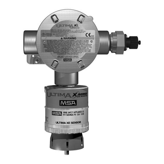
Introduction Introduction General Description The ULTIMA X Gas Monitor is designed to sample the environment where mounted and alert you to potentially dangerous levels of your target gas, depending on your particular model. The unit is factory-calibrated and shipped ready for installation. Identifying Your Unit The ULTIMA XT Gas Monitor is housed in a rugged, plastic general-purpose enclo- sure [... - Page 15 Introduction Fig. 2 Flameproof ULTIMA XL Monitor ULTIMA XL/ULTIMA XT...
- Page 16 Introduction The ULTIMA XIR Gas Monitor is housed in a 316 stainless steel flameproof enclo- sure [ Fig. 3]. Fig. 3 Flameproof ULTIMA XL with IR Monitor Remote Sensor Models are shown in Fig. 4, Fig. 5 and Fig. 6. ULTIMA XL/ULTIMA XT...
- Page 17 Introduction Fig. 4 General-Purpose XT Remote Sensor Model ULTIMA XL/ULTIMA XT...
- Page 18 Introduction Fig. 5 Flameproof XL Remote Sensor Model Fig. 6 Flameproof XIR Remote Sensor Model' ULTIMA XL/ULTIMA XT...
-
Page 19: Installing Your Gas Monitor
Introduction To determine your sensor type and options, check the shipping carton. Checked items are included in the carton. Also check the sensor ID label located on the sen- sor module. The carton label identifies: Type of unit supplied [Gas Monitor, Gas Monitor Less Sensor, or Sensing Module] Type of gas [combustible gas, toxic gas or oxygen] Range [% LEL, PPM [parts per million], or %]... -
Page 20: Installing The Ultima Xt Gas Monitor
Introduction Warning! Do not locate the general-purpose enclosure models in an area which may contain a flammable mixture of gas and air; otherwise, an explosion may occur. The general-purpose ULTIMA X Series Gas Monitors can be a source of ignition and must not be mounted in an area where a flam- mable mixture of combustible gas and air may become present;... -
Page 21: Installing The Ultima Xl Gas Monitor
Introduction Installing the ULTIMA XL Gas Monitor Fig. 7 Flameproof XIR Remote Sensor Model The ULTIMA XL Gas Monitor main enclosure can be rotated 360° and mounted to ensure easy access to any of the three entryways. The electronics assembly can be installed in any of the four self-aligning positions to allow proper sensor orientation. -
Page 22: Installing The Ultima Xir Gas Monitor
Introduction Installing the ULTIMA XIR Gas Monitor Warning! The ULTIMA XIR Combustible Gas Monitor contains no user- or field- serviceable parts and must be returned to the factory for repair. Any at- tempt to open the monitor will damage the unit and void the warranty. Fig. -
Page 23: Electrical Connections For Ultima X Gas Monitors
General Information Installation Instructions for Following the EMC Directives The devices of MSA have been developed and tested in accordance with the EMC Directives 89/336/EEC, 91/263/EEC, 92/31/EEC, and 93/68/EEC and the corre- sponding standards EN 50270. The requirements of the EMC Directives can only be met by following the manufacturer’s installation instructions. - Page 24 If additional high-voltage surge protection measures are required an appropri- ate high-voltage protection filter, approved by MSA, must be installed in the sen- sor cable. Instructions on Meeting the EMC Requirements on the ULTIMA XL...
- Page 25 Introduction Conduit may also be needed in areas where large amounts of electrical noise is ex- pected. Use caution when selecting a cable size. The following tables express the maxi- mum cable length when only using the ULTIMA X Series Gas Monitors. ULTIMA X Series options may take additional power which requires a heavier cable or a short cable run.
-
Page 26: Ultima Xir
Introduction ULTIMA XL and XT Maximum Cable Length and 4-20 mA Signal Load Power Supply 24 Volts Cable Size 1.00 mm Cable [18 AWG] 762 m [2500 ft] 1.50 mm Cable [16 AWG] 1280 m [4200 ft] 2.50 mm Cable [12 AWG] 3048 m [10000 ft] Max. - Page 27 Introduction Fig. 9 Circuit Board (1) Connect 24 VDC power lead to J1-1 [ Fig. 9]. (2) Connect J1-2 to 4 to 20 mA input on remote system. (3) Connect the signal ground to J1-3. (4) Connect the sensor module to labeled connector J-3 on the main pc board. (5) Assemble lid on enclosure.
- Page 28 Introduction Fig. 10 General-Purpose Three-Wire 4-20 mA Operation Fig. 11 Flameproof Three-Wire 4-20 mA Operation ULTIMA XL/ULTIMA XT...
-
Page 29: Installing The Ultima X Remote Sensor Module
Introduction 2.10 Installing the ULTIMA X Remote Sensor Module The Remote Sensor Module is used with the ULTIMA X Gas Monitor/less sensor. The Remote Sensor Module can be mounted in a manner similar to the gas monitor installation in the preceding procedure and at a maximum distance outlined in “Remote Module Wiring and Placement“. - Page 30 Introduction Remote Module Wiring and Placement Gas Type Minimum Wire Size Maximum Distance Toxic, Oxygen and 1.00 mm [18 AWG] 15.2 m [50 ft] Catalytic Combustible 1.50 mm [16 AWG] 30.5 m [100 ft] *IR Combustible 1.50 mm [16 AWG] 15.2 m [50 ft] 2.50 mm [12 AWG]...
-
Page 31: Start-Up And Calibration
Start-up and Calibration Start-up and Calibration Initial Start-up The ULTIMA X Series Gas Monitors are factory-calibrated and ready for imme- diate use. During the 30-second warm-up, the output signal is the same as the calibration signal when enabled during a normal calibration. This is described later in this chapter under "ULTIMA X Series Gas Monitor Calibration Output Signal". - Page 32 Start-up and Calibration Warning! In either mode, correct the condition causing the excessive gas level and vent or purge the area before attempting the following. In the +LOC % LEL mode, the output signal will also be locked at full-scale. If this condition occurs, the ULTIMA X Series Gas Monitor must be unlocked by perform- ing a "Zero Function"...
-
Page 33: Calibration Basics
Start-up and Calibration Green Operation Red LED 4-20 mA Output Sensor CAL Flashing ON 3.75 mA if cal signal enabled and Apply Span Gas ALERT option enabled; gas value sig- nal disabled 21.0 mA for oxygen if cal signal ena- bled and ALERT option disabled CAL 4-20... - Page 34 Start-up and Calibration Attention! To ensure a fully functional sensor, perform a calibration check and ad- justments at initial start-up and at regular intervals. Non-combustible Chemicals that Reduce Catalytic Sensor Sensitivity Catalytic Combustible sensors located in areas where non-combustible chemicals may leak, particularly ones known to reduce the sensitivity [see following list] should be calibrated after such exposures.
-
Page 35: Ultima X Series Gas Monitor Calibration Procedure
Start-up and Calibration ULTIMA X Series Gas Monitor Calibration Procedure Read all calibration instructions before attempting an actual calibration. Also, iden- tify and become familiar with all of the calibration components. During the calibra- tion, it is necessary to quickly apply the span gas to the unit. Prior connection of the calibration components will aid in the ease of unit calibration. -
Page 36: Span Gas Values
Start-up and Calibration The terms “trim” and “calibration” are used interchangeably within the HART protocol. To promote interoperability for users accustomed to ei- ther term, both are used in the menu structure. The calibration procedure for the sample draw ULTIMA XL/XT Monitor is the same as the procedure for the diffusion version, except calibration gas is applied to the calibration entry port of the inlet flow block and the cal kit for pumped units provides a flow matching regulator. - Page 37 Start-up and Calibration The lower explosive limits [LEL] of the gases and vapours in following table were taken from EN 61779. For gases and vapours not listed in EN 61779, the lower ex- plosive limits [LEL] were taken from the Chemsafe [Dechema, Frankfurt] data base. Local regulations may specify different LEL values;...
- Page 38 Start-up and Calibration ULTIMA XE - Relative response factors Relative response factors of tested gases for 0.89 vol% Propane calibration gas. Relative 100 % LEL- Response Response Measuring gas response in Vol% time [t time [t factor Acetone 2.5 Vol% 0.94 ≤...
- Page 39 Start-up and Calibration ULTIMA XL, with infrared gas sensor - ATEX performance approval When monitoring flammable gas in safety related applications the ULTIMA XL must be calibrated with a known concentration of the gas being monitored. The lower explosive limits [LEL] of the gases and vapours in the following tables were taken from EN 61779.
- Page 40 Start-up and Calibration Reference calibration example for Methanol when using propane: (1) Relative response factor for Methanol from the = 0.70 table in this section (2) Propane calibration gas concentration being used = 0.89 Vol% C (3) Propane volume concentration for 100 % LEL = 1.7 Vol% (4) Propane calibration gas concentration in % LEL 100 % LEL...
- Page 41 Start-up and Calibration Reference Gas Relative 100 % LEL in Linearisation Measuring gas Concentration response Vol% curve [Propane] factor n-Hexane 1.0 Vol% (6) Hexane 0.89 Vol% 1.27 Methanol 5.5 Vol% (3) Ethane 0.89 Vol% 0.70 n-Nonane 0.7 Vol% (2) Propane 0.89 Vol% 1.37 n-Pentane...
- Page 42 Start-up and Calibration 100 % LEL in Response to 50 % LEL of the Measuring gas Vol% measuring gas n-Butyl Acetate 1.3 Vol% 36 % LEL i-Butylene 1.6 Vol% 25 % LEL Cyclohexane 1.2 Vol% 31 % LEL Cyclopentane 1.4 Vol% 53 % LEL Diethyl Ether 1.7 Vol%...
- Page 43 Start-up and Calibration Factory-set Span Values SPAN Gas Preset Gas Type Range Values Carbon Monoxide 0-100 ppm; 60 ppm 0-500 ppm 300 ppm Sulfur Dioxide 0-25 ppm 10 ppm Hydrogen Sulfide 0-25 ppm 5 ppm 0-10 ppm 40 ppm 0-50 ppm 40 ppm Nitric Oxide 0-100 ppm...
- Page 44 Start-up and Calibration Item 1 - Tubing [P/N 711112] • 3/16" ID side connects to Item 3 • 1/4" ID side connects to sensor Item 2 - Zero Cap [P/N 710535] Item 3 - 1.5 LPM flow Controller [P/N 478358] Fig.
- Page 45 Start-up and Calibration If you wish to calibrate to the specific LEL of the gas or vapor being measured, the expected span gas value of the ULTIMA/ULTIMA X Series Gas Monitor can be changed by the HART Controller. Item 1 - Tubing [P/N 711112] •...
-
Page 46: Ultima X Series Gas Monitor Calibration
Calibration of Hydrogen Chloride Gas Monitors must be performed as follows: [Does only apply for non ex-approved ULTIMA XT version.] (1) Use MSA Hydrogen Chloride [HCl] cylinder [P/N 10028078], 40 ppm Hydro- gen Chloride. (2) Start with a NEW 1.5 LPM flow control regulator [P/N 478358] and tubing [P/N 711112] dedicated only for use with Hydrogen Chloride gas and included in Cal Kit #54. -
Page 47: Standard Calibration
Start-up and Calibration Standard Calibration A standard calibration includes a "zero" and "span" procedure as described in the following procedures. If the user chooses to only perform a "zero" procedure, they may do so by selecting the ZERO function on the HART communicator instead of the CALIBRATE selection as described as follows, or by using the optional push- button calibration as outlined in Chapter 2, "Optional Push-button Calibration". - Page 48 Start-up and Calibration The LEDs show: green LED flashing red LED OFF both LEDs flash once to indicate the 30-second countdown has expired. After the 30 second countdown: green LED is flashing red LED is OFF. Once the gas value is stable, the LED sequence will change. (4) If using the zero cap: remove it.
- Page 49 Start-up and Calibration Spanning (1) During a standard calibration, the ULTIMA X Series Monitor automatically be- gins the span countdown after a successful zeroing of the unit. The span countdown is 30 seconds. green LED is flashing red LED is ON. The span process can be aborted at any time during the countdown by simply selecting ABORT with the HART communicator or, by pressing and releasing the pushbutton if push-button calibration is used.
-
Page 50: Oxygen Calibration
Start-up and Calibration If a CAL FAULT appears on the HART communicator status display, or the red LED is on solid [not blinking], this indicate An unsuccessful attempt to calibrate the ULTIMA X Series Monitor The ULTIMA X Series Monitor is operating with the calibration parameters defined before the calibration was attempted. -
Page 51: Xir Calibration
Start-up and Calibration XIR Calibration Although a full calibration [zero and span] can be performed on the ULTIMA XIR Gas Monitor, a no-gas calibration is sufficient to properly calibrate the monitor. Typ- ically, a zero adjustment is all that is required for a full calibration. Normally, any degradation of the sensor's performance is associated with slight drifts in its zero response which, in turn, will adversely affect its span performance. -
Page 52: Optional Push-Button Calibration
Start-up and Calibration Optional Push-button Calibration The following procedure is used to enter the calibration by using the push-button. (1) Press and hold the push-button for at least one second. (2) Release the push-button. At this time, any recoverable alarms will be acknowledged [reset]. (3) Press and hold the push-button within three seconds of the first push-button release. - Page 53 Start-up and Calibration First warning screen Once the sensor calibration feature is selected, a warning message displays to in- dicate that the 4-20 mA output should be disabled from any automatic control loop to prevent false action during calibration. The user must acknowledge this screen to continue.
- Page 54 Start-up and Calibration Sensor Zero countdown screen Once the information screens are displayed, the device should start sending back a status byte to indicate calibration progress. The first status message should be the 30-second device countdown message. This message prompts user to start ap- plying Zero gas if necessary.
-
Page 55: Standard Calibration Procedures
Start-up and Calibration 3.11 Standard Calibration Procedures Standard Zero/Span Calibration Selection Menu Select Sensor Calibration from the Sensor Trim Menu Sensor calibration or “trim” functions are available from several locations in the menu structure. See Fig. 23 for a view of this selection menu. First warning screen Once the sensor calibration feature is selected, a warning message displays to in- dicate that the 4-20 mA output should be disabled from any automatic control loop... - Page 56 Start-up and Calibration Selection confirmation screen After the initiating screen displays for five seconds, a second information screen displays. This screen displays for five seconds and provides the user confirmation of the current calibration selection. No action is required at this screen, but the user may press the ABORT button to stop the process.
- Page 57 Start-up and Calibration Adjusting Span screen After the 30-second Span initialization, a Span adjustment screen displays and con- tinually updates with the gas [PV] reading, units and type information. Once the de- vice detects a stable reading, the data is stored automatically and the user is notified of the completion status.
-
Page 58: Initial Calibration Procedures
Start-up and Calibration 3.12 Initial Calibration Procedures Initial Calibration Selection Menu Initial calibration is selected in a manner similar to the standard Zero/Span calibra- tion procedure and the steps are similar [except the function selection should be “Initial Cal”]. Initial calibration should be run when a new sensor is connected to the unit or when a standard Zero/Span procedure will not clear a fault condition [such as when the wrong Span gas is used]. - Page 59 Start-up and Calibration Zero cal step screen Fig. 14 Path: Zero cal step screen Fig. 15 Zero cal step screen ULTIMA XL/ULTIMA XT...
- Page 60 Start-up and Calibration Span cal step screen Fig. 16 Path: Span cal step screen Fig. 17 Span cal step screen ULTIMA XL/ULTIMA XT...
-
Page 61: Sample Calibration Display Screens
Start-up and Calibration 3.14 Sample Calibration Display Screens HART DDL-based calibration display screens Fig. 18 Select Sensor Calibration from the Sensor Trim Menu ULTIMA XL/ULTIMA XT... - Page 62 Start-up and Calibration First warning screen Fig. 19 Path: First Warning screen Fig. 20 First Warning screen ULTIMA XL/ULTIMA XT...
- Page 63 Start-up and Calibration Second warning screen Fig. 21 Path: Second Warning screen Fig. 22 Second Warning screen ULTIMA XL/ULTIMA XT...
- Page 64 Start-up and Calibration Standard Calibration function select screen Fig. 23 Path: Standard Calibration function select screen Fig. 24 Standard Calibration function select screen ULTIMA XL/ULTIMA XT...
- Page 65 Start-up and Calibration Calibration initiated screen Fig. 25 Path: Calibration initiated screen Fig. 26 Calibration initiated screen ULTIMA XL/ULTIMA XT...
- Page 66 Start-up and Calibration Selection Confirmation Screen Fig. 27 Path: Selection Confirmation screen Fig. 28 Selection Confirmation screen ULTIMA XL/ULTIMA XT...
- Page 67 Start-up and Calibration Sensor Zero Countdown screen Fig. 29 Path: Sensor Zero Countdown screen Fig. 30 Sensor Zero Countdown screen ULTIMA XL/ULTIMA XT...
- Page 68 Start-up and Calibration Zero Adjustment screen Fig. 31 Path: Zero Adjustment screen Fig. 32 Zero Adjustment screen ULTIMA XL/ULTIMA XT...
- Page 69 Start-up and Calibration Span countdown screen Fig. 33 Path: Span countdown screen Fig. 34 Span countdown screen ULTIMA XL/ULTIMA XT...
- Page 70 Start-up and Calibration Adjusting Span screen Fig. 35 Path: Adjusting Span screen Fig. 36 Adjusting Span screen ULTIMA XL/ULTIMA XT...
- Page 71 Start-up and Calibration Calibration completion message Fig. 37 Path: Calibration completion message Fig. 38 Calibration completion message ULTIMA XL/ULTIMA XT...
- Page 72 Start-up and Calibration Calibration gas reminder screen Fig. 39 Path: Calibration gas reminder screen Fig. 40 Calibration gas reminder screen ULTIMA XL/ULTIMA XT...
- Page 73 Start-up and Calibration Loop control reminder message Fig. 41 Path: Loop control reminder message Fig. 42 Loop control reminder message ULTIMA XL/ULTIMA XT...
-
Page 74: Troubleshooting
Start-up and Calibration 3.15 Troubleshooting Fault indications Span Fault This fault can occur if the sensor is in cal mode and the required SPAN gas is not applied to the sensor at the indicated time or within the timeout period. This fault causes the 4-20 mA output to be set to the fault level [21 mA for Oxygen, 3 mA for all other sensors]. - Page 75 Start-up and Calibration Calibration status screen Fig. 43 Path: Calibration status screen Fig. 44 Calibration status screen ULTIMA XL/ULTIMA XT...
- Page 76 Start-up and Calibration Sensor trim point screen Fig. 45 Sensor trim point screen ULTIMA XL/ULTIMA XT...
- Page 77 Start-up and Calibration Additional Sensor status screen Fig. 46 Path: Additional Sensor status screen Fig. 47 Additional Sensor status screen ULTIMA XL/ULTIMA XT...
- Page 78 Start-up and Calibration Zero Fault The Zero Fault can be caused by a faulty sensor, calibration out of the Standard Zero/Span calibration range, sensor in change, sensor fault or attempting to zero the sensor with Span gas applied. The application of Zero gas should be checked and the sensor status [as defined in Fig.
- Page 79 Start-up and Calibration Device status screen Fig. 48 Path: Device status screen Fig. 49 Device status screen ULTIMA XL/ULTIMA XT...
-
Page 80: Specifications
Specifications Specifications Specifications Gas Types Combustibles, Oxygen & Toxics Temperature Toxics & Operating Range 0 to +40°C [32 to +104°F] Range Oxygen *Extended Ran- -20 to +50°C [-4 to +122°F] Operating Range 0 to +30°C [32 to +86°F] *Extended Range -10 to +40°C [-14 to +104°F] , Cl , ClO... - Page 81 Specifications Accuracy Linearity Repeatability Carbon Monoxide the greater of ±2% ±1% FS or 2 ppm full scale [FS] Oxygen 0 -25% v/v ±2% FS ±1% FS 0 -10% v/v ±3% FS Hydrogen Sulfide ±10% FS or 2 ppm ±1% FS or 2 ppm Chlorine ±10% FS or 2 ppm ±5% FS or 1 ppm...
- Page 82 Ammonia Full replacement 1 year from installation,10 years for IR warranty sensor source[see "MSA Instrument War- ranty" in this manual for complete details] Response time t may increase up to 50 seconds when used with SensorGard. sensor should not be used in dirty or humide environments.
- Page 83 Specifications Wiring Require- Oxygen,Toxics & ments Combustibles 3-wire Power Supply Oxygen & Toxics 24 VDC ±20 %, 55 mA max Catalytic 24 VDC ±20 %, Combustibles 350 mA max IR Combustibles 24 VDC ±20 %, 530 mA max Signal Output 4-20 mA Oxygen,Toxics &...
- Page 84 Specifications Sensor Response to Interferants If your readings are higher or lower than expected, it could be due to the presence of an interferant gas. The gas listed in column 1 is presented to the sensor. Column 2 indicates the concentration of that gas presented to the sensor. The remaining columns indicate the respective responses by the sensors to each particular gas.
- Page 85 Specifications Concentra- CO fil- fil- Interferant tion [ppm] tered tered Hydrogen Chloride Hydrogen Cyanide Hydrogen Fluoride Hydrogen -0.1 Sulfide Mercaptan -0.1 [Methyl] Methane 5000 Nitric Oxide Nitrogen Dioxide Phosphine Silane Sulfur Dioxide Tichloro- 1000 ethylene ND = No Data ULTIMA XL/ULTIMA XT...
- Page 86 Specifications Concentra- Interferant tion [ppm] Acetone 1000 Acetylene 12000 Ammonia Arsine Benzene Bromine Carbon Diox- 5000 Carbon Di- sulfide Carbon Mon- oxide Chlorine -0.2 Diborane Ethylene -0.3 Ethyl Alcohol 100 Ethyle Oxide 10 Ether Fluorine Freon 12 1000 Germane Hexane Hydrogen Hydrogen Chloride...
- Page 87 Specifications Concentra- Interferant tion [ppm] Mercaptan [Methyl] Methane 5000 Nitric Oxide Nitrogen Dioxide Phosphine Silane Sulfur -0.3 Dioxide Tichloro- 1000 ethylene ND = No Data Concentra- Interferant tion [ppm] Acetone 1000 Acetylene 12000 Ammonia Arsine Benzene Bromine Carbon Dioxide 5000 Carbon Disulfide 15 Carbon Monoxide...
- Page 88 Specifications Concentra- Interferant tion [ppm] Fluorine Freon 12 1000 Germane Hexane Hydrogen Hydrogen Chloride Hydrogen Cyanide Hydrogen Fluoride Hydrogen -0.2 Sulfide Mercaptan -0.2 [Methyl] Methane 5000 Nitric Oxide Nitrogen Dioxide 5 Phosphine Silane Sulfur Dioxide Tichloroethylene 1000 ND = No Data ULTIMA XL/ULTIMA XT...
-
Page 89: Hart Field Device Specification
Specifications HART Field Device Specification The MSA ULTIMA XL/XT Gas Detection Instrument, revision 2, complies with HART Protocol Revision 7 and uses the 16-bit manufacturer and device codes. This document specifies all the device specific features and documents the HART Pro- tocol implementation details [e.g., the Engineering Unit Codes supported]. -
Page 90: Product Overview
Specifications Device Identification Manufacturer Model Name [S] ULTIMA XL/XT Name Manufacture 0X6008 Device Type Code 0xe08c ID Code HART Protocol Device Revision Revision Number of Device Notes: Variables Physical Layers FSK, 4-20 mA Supported Physical Device Current Output Category Fig. 50 ULTIMA XL Gas Monitor Product Overview The ULTIMA XL/XT Gas Monitor is an instrument used to detect and measure gas... -
Page 91: Product Interfaces
Specifications ULTIMA XT Gas Monitor is a general-purpose version in a plastic enclosure for use in non-explosive atmospheres only. Product Interfaces Process Interface Sensor Input channel The main sensor input is provided via a five-terminal interface that provides a digital interface for 3 VDC or 5 VDC sensor modules. - Page 92 Specifications Local Interfaces, Jumpers and Switches Local Controls and Displays The ULTIMA XL/XT device has two dual-use LED indicators: one green "Normal" LED and one red "Alert" LED. The ULTIMA XL/XT device has one multi-use pushbutton used for the following pur- poses: Acknowledge- single push acknowledgement to release latched alarms if alarm level is no longer exceeded.
- Page 93 Specifications Device Variables Exposed by the ULTIMA XL/XT Monitor Variable Description Variable Description Gas Type Sensor gas type Last Cal Date Date sensor was description last calibrated Alarm Setpoints Gas value at which Auto Zero comp Amount of compen- an alarm status bit sated below zero is set drift...
- Page 94 Specifications Status Information Device Status Bit 4 ["More Status Available"] is set when any failure is detected. Command #48 gives further details. Extended Device Status The ULTIMA XL/XT Monitor can predict when certain maintenance will be required. This bit is set if a sensor fault or maintenance warning is detected. "Device Variable Alert"...
- Page 95 Specifications Device Status Bits Byte Meaning Class Cal Aborted Info Zero Fault Info Span Fault Info Cal OK Info End of Life Warning Warning Sensor Swap Delay Info Change Sensor Fault Error Sensor Power Fault Error Internal Comm Fault Error Cal Sig Enable Info Alert Option Enable...
-
Page 96: Universal Commands
Specifications Universal Commands All Universal commands have been implemented in the ULTIMA XL/XT Gas Moni- tor. The ULTIMA XL/XT Gas Monitor returns a 7 in the Universal rev to indicate the device is using the expanded 16-bit manufacturer and device codes. Common-Practice Commands The following Common Practice commands have been implemented in the ULTIMA XL/XT device:... - Page 97 Specifications Device-Specific Commands Command # Description Read Sensor Gas Type Read Device RTC Read Alarm Setpoints Read Alarm Control Actions Read Min/Max/Average Values Read Last Cal Date Read Gas Table Read Input Voltage Read Auto Zero Comp Read Read GT60 Version Read Sensor Status Read Swap Delay Status Read Cal Signal Status...
- Page 98 Specifications Command #129: Read Sensor Gas Type Reads the Gas Type of the sensor currently connected to the ULTIMA XL/XT Gas Monitor. Request Data Bytes None. Response Data Bytes Byte Format Description ASCII Sensor gas type description Command #130: Read Device Real Time Clock Reads the Real Time clock hours and minutes from the ULTIMA XL/XT Gas Monitor.
- Page 99 Specifications Response Data Bytes Byte Format Description Float Alarm 1 Setpoint Value Float Alarm 2 Setpoint Value 8-11 Float Alarm 3 Setpoint Value Command #132: Read Alarm Control Actions Reads the ULTIMA XL/XT Alarm Control Actions. Request Data Bytes None. Response Data Bytes Byte Format...
- Page 100 Specifications Command #134: Read Last Cal Date Returns the ULTIMA XL/XT last calibration date of the currently connected sensor. Request Data Bytes None. Response Data Bytes Byte Format Description Unsigned Last sensor calibration date Command #135: Read Gas Table This command returns the ULTIMA XL/XT sensor Gas Table currently in use. The Gas Tables are linearization reference tables used with certain sensors to provide accurate response for different gases from the same sensor.
- Page 101 Specifications Command #138: Read GT60 Version Returns the ULTIMA XL/XT main processor code version number as a two byte un- signed integer. Request Data Bytes None. Response Data Bytes Byte Format Description Unsigned GT60 version number Command #139: Read Sensor Status message Returns the ULTIMA XL/XT sensor status message.
- Page 102 Specifications Command #141: Read Cal Signal Status This command returns the ULTIMA XL/XT Cal Signal status. This is a single byte containing a 0 if disabled or 1 if enabled. If enabled, the output will be set to 3.75 mA during calibration [21 mA for oxygen].
- Page 103 Specifications Request Data Bytes Byte Format Description Unsigned Alarm Number [1, 2, or 3] Float Alarm Setpoint Value Response Data Bytes Byte Format Description Unsigned Alarm Number Float Alarm Setpoint Value Request Data Bytes Byte Format Description Unsigned Alarm Number [1, 2, or 3] Bit Enum Alarm Control Action Value Response Data Bytes...
- Page 104 Specifications Command-Specific Response Codes Code Class Description Success No Command-specific errors 1 - 2 Undefined Error Parameter too large Undefined Error Too few data bytes Undefined Error In write protect mode 8 - 15 Undefined Error Access Restricted 17 - 31 Undefined Error Busy...
- Page 105 Specifications Command-Specific Response Codes Code Class Description Success No Command-specific errors 1 - 2 Undefined Error Parameter too large Error Parameter too small Error Too few data bytes Undefined Error In write protect mode 8-15 Undefined Error Access Restricted 17-18 Unrestricted Invalid device variable index 20 - 31...
- Page 106 Specifications Response Data Bytes Byte Format Description Unsigned Alarm Number [1, 2, or 3] Bit Enum Alarm Control Action Value[see Alarm Control Actions] Command-Specific Response Codes Code Class Description Success No Command-specific errors 1 - 4 Undefined Error Too few data bytes Undefined Error In write protect mode...
- Page 107 Specifications Command-Specific Response Codes Code Class Description Success No Command-specific errors Undefined Invalid Selection 3 - 4 Undefined Error Too few data bytes Undefined Error In write protect mode 8 - 15 Undefined Error Access restricted 17 - 31 Undefined Error Busy 33 - 127...
- Page 108 Specifications Command-Specific Response Codes Code Class Description Success No Command-specific errors 1 - 2 Undefined Error Parameter too large Error Parameter too small Error Too few data bytes Undefined Error In write protect mode 8 - 15 Undefined Error Access restricted 17 - 31 Undefined Error...
- Page 109 Specifications Command-Specific Response Codes Code Class Description Success No Command-specific errors 1 - 2 Undefined Error Parameter too large Error Parameter too small Error Too few data bytes Undefined Error In write protect mode 8 - 15 Undefined Error Access restricted 17 - 31 Undefined Error...
- Page 110 Specifications Command #179: Write Sensor Data Sheet Reset Control Writes a data sheet reset command to ULTIMA XL/XT Gas Monitor. This command causes the ULTIMA XL/XT Monitor to reset the current sensor data sheet to factory default settings. This command will set certain device warning status bits and re- quire the user to re-calibrate the sensor.
- Page 111 Specifications Command #180: Write Sensor Swap Delay Enable This command writes command number to the ULTIMA XL/XT Gas Monitor to en- able or disable the two-minute swap delay feature. This device feature enables a two-minute hold-off of the sensor missing fault, allowing the user to “Swap” or change sensor modules without having the 4-20 mA set to the fault condition.
- Page 112 Specifications Command #181: Write Cal Signal Enable This command writes command number to the ULTIMA XL/XT Gas Monitor to en- able or disable the Cal signal output. Without the Cal Signal enabled, the 4-20 mA output will follow the gas reading during calibration. With the Cal Signal enabled, the 4-20 mA output will be set to 3.75 mA during calibration and be held there for one minute after calibration has ended to allow the sensor to re-stabilize.
- Page 113 Specifications Command #182: Write Calibration Mode This command writes a calibration mode number to the ULTIMA XL/XT Gas Moni- tor. The mode commands initiate a calibration sequence in the device. Device sta- tus byte 2 can be monitored to determine the progress of the calibration. Request Data Bytes Byte Format...
- Page 114 Specifications Command #183: Write Calibration Abort This command writes a calibration Abort command to the ULTIMA XL/XT Gas Mon- itor. The calibration abort command instructs the device to suspend the calibration sequence initiated by the calibration mode command. Valid number for this com- mand is 1.
- Page 115 Specifications Command #184: Write Calibration Step This command writes a calibration Step Command to the ULTIMA XL/XT Gas Mon- itor. The Step command instructs the device to advance to the next step during a manual calibration sequence. Device status byte 2 can be monitored to determine the progress of the calibration.
- Page 116 Specifications Command #185: Write Alarm Acknowledge This command writes an Alarm Acknowledge command to the ULTIMA XL/XT Gas Monitor. The alarm acknowledge command instructs the device to clear any latched alarms in the device, provided the setpoint level for the alarm has receded. Valid command number is on 1.
- Page 117 Specifications Request Data Bytes Byte Format Description Enum Write protect Mode [0 = disable, 1 = Enable] Response Data Bytes Byte Format Description Enum Write protect Mode [0 = disable, 1 = Enable] Command-Specific Response Codes Code Class Description Success No Command-Specific Errors Error Invalid Selection...
- Page 118 Specifications Response Data Bytes Byte Format Description Enum Alert Option Mode [0 - disabled, 1 - enabled] Command-Specific Response Codes Code Class Description Success No Command-Specific Errors Error Invalid Selection Error Parameter too large Error Parameter too small Error Too few data bytes Undefined Error In write protect mode...
- Page 119 Specifications Alarm Control Actions Bit0 Alarm Enable 1 = enabled, 0 = disabled Bit1 Alarm Direction 1 = increasing, 0 = decreasing Bit2 Alarm Latch Status 1 = latching, 0 = non-latching Bit3-7 Unused Gas Table Values Table Description Methane Propane Ethane n-Butane...
- Page 120 Specifications Sensor Status Codes Code Description 0x01 Flash Fault 0x05 Ram Fault 0x07 Pellement Fault 0x0A Data Sheet Fault 0x1E Power Fault 0x1F IR Factory Mode 0x20 IR Lamp Fault 0x28 EEPROM R/W Fault 0x2D EEPROM Checksum Fault 0x2F Sensor Missing Fault 0x3A Negative Power Supply Fault 0x3B...
-
Page 121: Performance
Specifications Performance Typical sampling rates are shown in the following table. Sampling Rates Gas Samples 4 per second PV digital value calculation 5 per second Analog output update 5 per second Power-Up On power-up, the transmitter goes through a self-test procedure [see Chapter 4, "Self-Test"], and a sensor warm up and initialization period which takes approxi- mately 30 seconds. - Page 122 Specifications Self-Test The self-test procedure is executed at power-up or following Command 42 ["Device Reset"]. Some self-test procedures are continuously run in a background mode. The self-test includes: Microprocessor Program ROM Configuration storage EEPROM Sensor communications Data sheet integrity Internal communications. This self-test takes about 10 seconds.
-
Page 123: Capability Checklist
Damping Damping is internally-fixed, affecting only the PV and the loop current signal. There is no user-settable damping control. Capability Checklist Manufacturer, model and revision MSA, ULTIMA XL/XT, rev. 2 Device type Transmitter HART revision Device Description available Number and type of sensors... -
Page 124: Default Configuration
Specifications Default Configuration Parameter Default Value Lower Range Value Upper Range Value Sensor dependent PV Units Sensor dependent Sensor type various Number of wires Damping time constant Fault-indication jumper Sensor dependent Write-protect mode write enabled Number of response preambles Alarms Enabled ULTIMA XL/ULTIMA XT... -
Page 125: Marking, Certificates And Approvals According To The Directive 94/9/Ec [ Atex ]
Specifications Marking, Certificates and Approvals according to the Directive 94/9/EC [ ATEX ] Manufacturer: Mine Safety Appliances Company 1000 Cranberry Woods Drive Cranberry Township, PA 16066 USA Product: ULTIMA XL Control Unit A-ULTIMAX-L-b-H-d-e-f-1-0-i-00-00-I-m-n b = Gas Type: Any two digit number d = Enclosure Type: 2 or 3 e = Sensor Mounting Style: S or D. - Page 126 Specifications Note: arrangement may be different or include additonal information not related to this approval. EC-Type Examination Certificates: FM 07 ATEX 0001 X and FM 07 ATEX 0004 X Quality Assurance Notification:0080 Year of Manufacture: see Label Serial Nr.: see Label EN 50270 Type 2 EN 61000-6-3 EN 61000-6-4 Special Conditions for Safe Use Upon installation of the ULTIMA XL Control Unit, the label shall be permanently...
- Page 127 Specifications Marking: ULTIMA XE SENSOR II 2 G Ex d IIC T4 FM07ATEX0031X EN 61779-4, EN 50104 -40°C ≤ Ta ≤ +60°C Note: arrangement may be different or include additonal information not related to this approval. Date: Included in Serial Number [SN], First Letter = A to L [January to December], next two digits indicate year of manufacture.
- Page 128 Specifications Special Conditions for Safe Use In order to maintain the performance of the system for Gas Types 31, 32, 33, 51, 52 or 53 the control unit to which this instrument is connected to shall also comply with the requirements of EN 61779-1. EN 61779-4 and EN 50271 as ap- propriate.
- Page 129 Specifications Date: Included in Serial Number [SN], First Letter = A to L [January to December], next two digits indicate year of manufacture. EC-Type Examination Certificate: FM 07 ATEX 0032 X Quality Assurance Notification: 0080 EMC Conformance according to the Directive 89/336/ECEN 50270 Type 2 EN 61000-6-3 EN 61000-6-4 Special Conditions for Safe Use In order to maintain the performance of the system for Gas Types 38, 39, 58 or...
- Page 130 Mine Safety Appliances Company 1000 Cranberry Woods Drive Cranberry Township, PA 16066 USA Product: MSA ULTIMA XE Type of protection: EN 50 014, EN 50 018 Performance: EN 61779-1, EN 61779-4, EN 50104, EN 50271 Int.Relais +LEDs, UB=19 V-30 V,Ia= 4-20 mA,3-Wire...
-
Page 131: Maintenance
Maintenance Maintenance General The ULTIMA XL/XT Series Gas Monitor is constantly performing a self check. When a problem is found, it displays the appropriate error message. [see "Trouble- shooting Guidelines"]. When a critical error is detected within the unit, the output signal goes to a fault condition. - Page 132 Do not install a leaking sensor in the sensing head assembly. The leak- ing sensor must be disposed of in accordance with local, state and fed- eral laws. To obtain a replacement sensor, contact MSA at the address given under "Obtaining Replacement Parts."...
- Page 133 Maintenance (1) There is no need to open the main enclosure; simply unscrew the sensor as- sembly located on the bottom of the ULTIMA X Series Gas Monitor main as- sembly [ Fig. 51]. Warning! Do not open, connect, disconnect, or change any sensor when an explo- sive gas atmosphere may be present or any circuits are energized.
- Page 134 Maintenance It is recommended that all other maintenance be performed at an MSA factory-au- thorized service center. Troubleshooting Guidelines Message Indicates Action CHANGE SEN- Sensor is at its end of life Replace sensor CAL FAULT Instrument did not calibrate Repeat calibration; check for successfully proper calibration gas;...
- Page 135 Repair or alteration of the ULTIMA X Series Gas Monitor, beyond the scope of these maintenance instruc- tions or by anyone other than authorized MSA service personnel, could cause the product to fail to perform as designed and persons who rely on this product for their safety could sustain serious personal injury or loss of life.
-
Page 136: Ordering Information
Ordering Information Ordering Information ULTIMA XL Housing & PCB 3/4'' NPT 25 mm metric With HART port 10094883 10094885 Without HART port 10094884 10094886 ULTIMA XL Sensors Infrared Sensors Combustible Gases, IR, Group 3 0 - 100 % LEL 10044425 10044449 Combustible Gases, IR, Group 4 0 - 100 % LEL 10044426... - Page 137 Ordering Information ULTIMA XT Complete Unit Ammonia 0 - 50 ppm 10095397 Ammonia 0 -100 ppm 10094890 Ammonia 0 -1000 ppm 10095398 Arsine 0 - 2 ppm 10095401 Bromine 0 - 5 ppm 10095370 Carbon Monoxide 0 - 100 ppm 10095392 Carbon Monoxide 0 - 500 ppm...
- Page 138 Ordering Information ULTIMA XL Accessories Mounting bracket 10047562 Duct mount kit Mounting bracket with cuct mount kit SensorGard for XL/XE 10028904 SensorGard for XLIR/XIR 10041265 Flow cap for XL/XE 10041866 Flow cap for XLIR/XIR 10042600 Replacement Parts P/N for Spare Sen- P/N for Spare Sensor, Gas Selection sors, ULTIMA XL,...
- Page 139 Ordering Information P/N for Spare Sen- P/N for Spare Sensor, Gas Selection sors, ULTIMA XL, ULTIMA XL, M25 Thread 3/4" NPT Thread Phosphine, 2 ppm 10044486 10044486 Arsine, 2 ppm 10044487 10044487 Silane, 25 ppm 10044488 10044488 Germane, 3 ppm 10044489 10044489 Diborane, 50 ppm...
- Page 140 Ordering Information Sensor Kit P/N Explosion-Proof & Gas Selection General-Purpose flameproof Models Models A and T E and L Combustible Gas, 100% LEL A-ULTX-SENS-52-8 Petroleum Vapors Combustible Gas, 100% LEL A-ULTX-SENS-53-8 Solvents Comb Gas IR - not available A-ULTX-SENS-58-9 [metric] Methane, 4.4 % CH A-ULTX-SENS-58-10 [NPT]...
-
Page 141: Appendix
Appendix Appendix Installation Drawings Check tag for area classification Mount unit with sensor inlet facing down Fig. 52 ULTIMA XT Sensor/Transmitter Front ULTIMA XL/ULTIMA XT... - Page 142 Appendix Fig. 53 ULTIMA XT Sensor/Transmitter Side ULTIMA XL/ULTIMA XT...
- Page 143 Appendix P/N 10047561 is optional mounting bracket Fig. 54 Optional Mounting Bracket XT ULTIMA XL/ULTIMA XT...
- Page 144 Appendix Fig. 55 Wiring Connections ULTIMA XL/ULTIMA XT...
- Page 145 Appendix Check Tag for area classification Check Tag for area classification (Mount unit with sensor inlet facing down) Fig. 56 ULTIMA XL [w/o Com Port] ULTIMA XL/ULTIMA XT...
- Page 146 Appendix Fig. 57 ULTIMA XL [with Com Port] ULTIMA XL/ULTIMA XT...
- Page 147 Appendix Fig. 58 ULTIMA XL [with Com Port and adapter] ULTIMA XL/ULTIMA XT...
- Page 148 Appendix P/N 10047562 is optional mounting bracket P/N 10047562 is optional mounting bracket Fig. 59 Optional Mounting Bracket ULTIMA XL/ULTIMA XT...
- Page 149 Appendix Mount unit with sensor inlet horizontal Check tag for area classification Fig. 60 ULTIMA XL with XIR Sensor Fig. 61 ULTIMA XL with XIR Sensor [with Com port] ULTIMA XL/ULTIMA XT...
- Page 150 Appendix P/N 10047562 is optional mounting bracket P/N 10047562 is optional mounting bracket Fig. 62 Optional Mounting Bracket ULTIMA XL/ULTIMA XT...
- Page 151 Appendix ULTIMA XL/ULTIMA XT...
Need help?
Do you have a question about the ULTIMA XL Series and is the answer not in the manual?
Questions and answers