MSA ULTIMA X Operating Manual
Gas monitors with x3 technology
Hide thumbs
Also See for ULTIMA X:
- Instruction manual (29 pages) ,
- Instruction manual addendum (30 pages)

Related Manuals for MSA ULTIMA X


Summary of Contents for MSA ULTIMA X
- Page 1 Operating Manual ® ULTIMA 3 TM Gas Monitors with X Technology Addendum Order No.: 10082867/00...
- Page 2 MSA AUER GmbH D-12059 Berlin Thiemannstrasse 1 Germany © MSA AUER GmbH. All rights reserved...
- Page 3 Manufactured by: Mine Safety Appliances Company 1000 Cranberry Woods Drive Cranberry Township, PA 16066 USA The manufacturer or the European Authorized Representative: MSA AUER GmbH, Thiemannstraße 1, D-12059 Berlin 3 TM ® declares that the product: MSA ULTIMA XE / X...
- Page 4 DECLARATION OF CONFORMITY Marking, Certificates and Approvals according to the Directive 94/9/EC (ATEX). Manufacturer: Mine Safety Appliances Company 1000 Cranberry Woods Drive Cranberry Township, PA 16066 USA ® 3 TM Product: ULTIMA XE / X Type of protection: EN 50 014, EN 50 018 Performance: none ULTIMA XE/ X...
- Page 5 ® 3 TM ULTIMA...
-
Page 6: Table Of Contents
Components....................9 Installation ......................11 3.1. Instructions for installation................ 11 3.2. Installation with Mounting Kit..............12 3 TM 3.3. Electrical connection for ULTIMA X instruments ....... 13 Operation ......................15 4.1. Hand-held Controller and Calibrator............15 4.2. ModBUS Addressing................16 4.3. - Page 7 CONTENTS Appendix A Electrical installation ............... 25 A-1. Installation Drawings ................25 A-2. Cable Lengths and Power Consumption ..........25 A-3. Connection Drawings ................27 Appendix B ModBUS User Configuration Data ..........28 B-1. ModBUS User Configuration Data............28 B-2. Alarm Function Codes - Word 1 ...............
-
Page 8: Safety Regulations
Alternative use, or use outside this specification will be considered as non- compliance. This also applies especially to unauthorised alterations to the apparatus and to commissioning work that has not been carried out by MSA or authorised persons. Danger! This product is supporting life and health. -
Page 9: Safety And Precautionary Measures To Be Adopted
SAFETY REGULATIONS 1.3. Safety and Precautionary Measures to be Adopted Attention! The following safety instructions must be observed implicitly. Only in this way can the safety and health of the individual operators, and the correct functioning of the instrument, be guaranteed. The instruments are used to detect gases or vapours in air. -
Page 10: Description
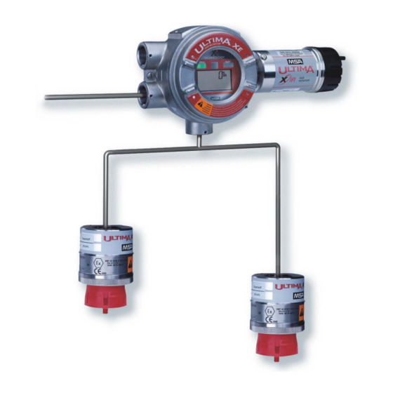
DESCRIPTION Description ® 3 TM The ULTIMA instruments are housed in a flameproof enclosure and are calibrated at the factory ready for installation. The instrument components vary somewhat depending on the particular model. All models are provided with either ¾“ NPT or M25 x 1.5 cable entries. 2.1. -
Page 11: Components
DESCRIPTION 2.2. Components Display The display cycles through each connected sensor showing the gas type, gas concentration and sensor number. Fig. 2 Sensor Display View Gas Type Display Heartbeat - acknowledges commu- nications activity from ModBUS or IR Controller/Calibrator command Gas Concentration Display Sensor Number Gas Concentration Display with Alarm... - Page 12 The ULTIMA is shipped with all gas alarm relays configured for 3 alarm levels common to all sensors. Using the ULTIMA/ULTIMA X Controller Section 4.1) or ModBUS command each relay can be assigned to one sensor, providing one level of alarm for each.
-
Page 13: Installation
Instruments from the ULTIMA Gas Monitors must be protected from external vibrations and direct sunlight. For details of the instrument cabling and electrical connection Appendix A-1) and the installation drawings in the ULTIMA X Series Operating Manual (Order No. 10050078). ® 3 TM... -
Page 14: Installation With Mounting Kit
INSTALLATION 3.2. Installation with Mounting Kit ® 3 TM ULTIMA Gas Monitors are installed at the place of installation on a mounting plate. Fig. 3 Mounting plate Wall mounting fixing holes Instrument fixing holes Use Ø6 x 20 mm screws and suitable plugs for attaching the mounting plate to the wall. -
Page 15: Electrical Connection For Ultima X 3 Tm Instruments
INSTALLATION 3 TM 3.3. Electrical connection for ULTIMA X instruments Attention! The ULTIMA X³ instruments must be installed only in compliance with the applicable regulations, otherwise safe operation of the instrument is not guaranteed. Ensure all sources of electrical power are disconnected before ®... - Page 16 INSTALLATION Fig. 4 Typical ModBUS Network Topography Communications Cable Trunk Communications Cable Branch Communications and Power Cables remote sensor ModBUS Master Device COM line termination device DC or AC Power Source Device 1 Device 2 Local DC or AC Power Source Device n COM line termination device ®...
-
Page 17: Operation
OPERATION Operation 4.1. Hand-held Controller and Calibrator The intrinsically safe ULTIMA/ULTIMA X Series Controller and Calibrator are ® 3 TM used to calibrate and change or view the configuration of ULTIMA Monitors. ® 3 TM All firmware versions of the Calibrator will work with the ULTIMA Gas Monitors but the Controller must have firmware version 3.03 or... -
Page 18: Modbus Addressing
The ModBUS slave address has a valid range of 1-247. The default value is 247. This address may be set using a ULTIMA/ULTIMA X Controller or Calibrator or a ModBUS Controller. The Calibrator address range is limited to 0-32, for other addresses use the Controller. -
Page 19: Modbus Communications
OPERATION 4.3. ModBUS Communications The communications protocol is ModBUS RTU over an RS-485 hardware network. The default settings for communications parameters are 19200 baud and even parity. The stop bits are fixed at 1 stop bit. For data types that are larger than one word, the most significant word is located in the first register (big- endian). -
Page 20: Modbus Factory Configuration Data (Read Only)
OPERATION For systems that use five-digit addressing, 4XXXX: If the first digit is an internal system requirement and does not appear in the communications packet, write the value 1000 to address 41000. The base address is now 41000 and the first valid address is 41001. If all five digits appear in the communications packet, the default base address is 40000 and the first valid address is 40001. -
Page 21: Calibration
For complete calibration details please refer to the “ULTIMA/ULTIMA X Series Operating Manual” (Order No.: 10050078). Connect power to the ULTIMA X Gas Monitor at least one hour before attempting a calibration. Carry out the calibration during commissioning as well as at regular intervals. -
Page 22: Optional Reset Button
Normally Open Switch The RESET push button must be installed remotely and not directly into the Ultima X cable gland entry. The switch must be fitted in an approved junction box and be ATEX approved for hazardous area use. The optional RESET button is to allow latching relays to be reset at the gas monitor location. -
Page 23: Modbus Port
RESET push button until the heart symbol is displayed. When the push button is released the calibration will be aborted. For calibration details refer to the ULTIMA/ULTIMA X Operating Manual (Order No.: 10050078). 5.2. -
Page 24: Maintenance
MAINTENANCE Maintenance The ULTIMA X Series Gas Monitors constantly perform a self check. If a problem is detected, the appropriate error message is displayed. For more and detailed information refer to ULTIMA/ULTIMA X Operating Manual (Order No.: 10050078). Attention! Use only genuine MSA replacement parts when performing any maintenance procedures provided in the manual. -
Page 25: Technical Data
TECHNICAL DATA Technical Data 7.1. Dimensions, weight XE enclosure Dimensions W x H x D (mm) 162 x 262 x 100 Weight approx. 5 kg 7.2. Performance Specifications Gas types Combustible gases, oxygen and toxic gases Operating range 0°C to 40°C Extended range -20°C to +50°C Toxic gases and... -
Page 26: Order Information
MBUS - PCB, with Relays, no LEDs 10062615 ULTIMA X MBUS - PCB, with Relays, with LEDs 10062616 For more and detailed information about accessories and spare sensors refer to ULTIMA/ULTIMA X Operating Manual (Order No.: 10050078). ® 3 TM ULTIMA... -
Page 27: Appendix A Electrical Installation
The cabling and electrical installation must be carried out based on the instrument types used. Electrical installation details are given in the appropriate drawings. Please refer to ULTIMA/ULTIMA X Operating Manual (Order No.: 10050078). A-2. Cable Lengths and Power Consumption Cable length Maximum power cable length depends on sensor configuration and wire gauge. - Page 28 ELECTRICAL INSTALLATION Remote Sensor Power Consumption Sensor Type Maximum Power Consumption 4.5 W 5.0 W E-Chem 1.5 W RS485 Communications Characteristics of the three-core cable: Cross Sectional Area 0.5 mm A = Transmit + / Receive + B = Transmit - / Receive - C = Common (GND) Maximum cable length: Trunk - 1000 m, Branch - 18 m Line Termination 120 Ω...
-
Page 29: A-3. Connection Drawings
ELECTRICAL INSTALLATION A-3. Connection Drawings ACKNOWLEDGE ACKNOWLEDGE PUSHBUTTON PUSHBUTTON Fig. 6 Typical Communications Wiring Scheme Network Trunk Line Terminal Network Branch Master Transmit + / Receive + Slave 1 Transmit - / Receive - Slave n Common ® 3 TM ULTIMA... -
Page 30: Appendix B Modbus User Configuration Data
MODBUS USER CONFIGURATION DATA Appendix B ModBUS User Configuration Data B-1. ModBUS User Configuration Data (Read/Write) Description Address Possible Values ModBUS Slave Address Base +101 1 ... 247 Baud Rate Code Base +102 0 – 1200, 1 – 2400 2 – 4800, 3 – 9600 4 –... -
Page 31: B-2. Alarm Function Codes - Word 1
MODBUS USER CONFIGURATION DATA B-2. Alarm Function Codes - Word 1 (Read/Write at Address Base +137) Name Bits Function Description Alarm 1 Enable, Sensor 1, 1 - Enable, 0 - Disable Alarm 1 Enable, Sensor 2, 1 - Enable, 0 - Disable Alarm 1 Enable, Sensor 3 1 - Enable, 0 - Disable Alarm 2 Enable, Sensor 1... -
Page 32: B-4. Modbus Device Status
MODBUS USER CONFIGURATION DATA B-4. ModBUS Device Status (Read only) Description Address Possible Values General Status-Bits Base +201 0..32767, see details below Fault-Status-Bits Base +202 0..32767, see details below Reserve Base +203 Gas-Type - Sensor 1 Base +204 See Appendix B-10 for detail Gas-Type - Sensor 2 Base +205 See Appendix B-10 for detail... -
Page 33: B-5. Modbus General Status Bits
Drift Counter - Sensor 2 Base +248 0 ... 20 Drift Counter - Sensor 3 Base +249 0 ... 20 ULTIMA X Internal Error Code Base +250 For further implementation Internal Error Code - Sensor 1 Base +251 For further implementation... -
Page 34: B-6. Modbus Fault Status Bits
Sensor End of life - Sensor 2 Set when any fault is detected Sensor End of life - Sensor 3 Set when any fault is detected ULTIMA X Configuration Reset Set when a datasheet reset occurs Not used B-7. Control Words (Read/Write) -
Page 35: B-8. Modbus Command Word 1
MODBUS USER CONFIGURATION DATA B-8. ModBUS Command Word 1 (Read at Address Base +301, Write Coils 1 through 16) Name Bits Coil Function Description Start Full ICAL Calibration - Sensor 1 Rtn's fault if any Calibration in progress Start Full ICAL Calibration - Sensor 2 Rtn's fault if any Calibration in progress Start Full ICAL Calibration - Sensor 3 Rtn's fault if any Calibration in progress... -
Page 36: B-10. Gas Type
IRIS - start IRIS - cont. IRIS - finish 257 CO 100 PPM, 1 PPM, MSA 25E/F, 60 PPM CO 500 PPM, 1 PPM, MSA 25E/F, 300 PPM 25 PPM, 1 PPM, CTL 7ST/F, 10 PPM S 10.0 PPM, 0.1 PPM, MSA HS25B, 5.0 PPM S 50.0 PPM, 0.1 PPM, MSA HS25B, 40 PPM... -
Page 37: B-11. Sensor Engineering Units
MODBUS USER CONFIGURATION DATA B-11. Sensor Engineering Units Unit Label Value Unit Label None % LEL Future Expansion B-12. Information Flags Word 1 (Read at Address Base +254) Name Bits Function Description Sensor 1 Disabled 0 = enabled, 1 = disabled Sensor 2 Disabled 0 = enabled, 1 = disabled Sensor 3 Disabled... -
Page 38: B-14. Information Flags Word 3
MODBUS USER CONFIGURATION DATA B-14. Information Flags Word 3 (Read at Address Base +256) Name Bits Function Description Overrange Flag Sensor 1 Set if TRUE Overrange Flag Sensor 2 Set if TRUE Overrange Flag Sensor 3 Set if TRUE LOC Flag Sensor 1 Set if TRUE LOC Flag Sensor 2 Set if TRUE... -
Page 39: B-16. Alternate Gas Readings
MODBUS USER CONFIGURATION DATA B-16. Alternate Gas Readings (Read and Write at Address Base +258 to Base +260) Description Value Normal Gas Detection 400 - 2000 Fault Overrange 2110 Suppressed Disabled ® 3 TM ULTIMA... -
Page 40: Appendix C Option For Internal Relay
These effects may damage the instrument and make it inoperative. ® One way to reduce these effects is to install a “Quencharc ”, available from MSA as part number 630413, across the load being switched. Attention! ®... - Page 41 OPTION FOR INTERNAL RELAY Re-install the connector plugs to the correct printed circuit board locations. Make sure the connector terminal plugs are completely pushed in to the printed circuit board sockets. (7) Pull the cable from the instrument to remove any excess slack. To avoid unwanted electrical noise it is important not to have any excess wire or cable inside the enclosure ®...
- Page 42 MSA in Europe www.msa-europe.com & www.msa-gasdetection.com Northern Europe Southern Europe Eastern Europe Central Europe Netherlands Italy Poland Germany MSA Nederland MSA Italiana MSA Poland MSA AUER Kernweg 20, 1627 LH Hoorn Via Po 13/17 ul. Wschodnia 5A Thiemannstrasse 1 Phone +31 [229] 25 03 03...
Need help?
Do you have a question about the ULTIMA X and is the answer not in the manual?
Questions and answers