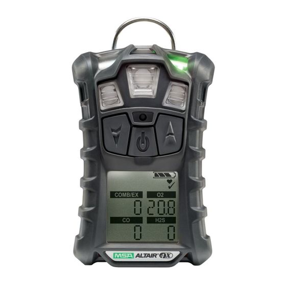
MSA ALTAIR 4 Operating Manual
Four gas multigas detector
Hide thumbs
Also See for ALTAIR 4:
- Quick start card (40 pages) ,
- Service manual (34 pages) ,
- Calibration manual (3 pages)

Related Manuals for MSA ALTAIR 4


Summary of Contents for MSA ALTAIR 4
- Page 1 Operating Manual ® ALTAIR 4 – Four Gas Multigas Detector Manufactured by MSA CORPORATE CENTER 1000 Cranberry Woods Drive, Cranberry Township, Pennsylvania 16066 P/N 10088975 Rev 1 Y-HLS...
- Page 2 WARNING Read this manual carefully before using the instrument. The instrument will perform as designed only if it is used and maintained in accordance with the manufacturer's instruction. Otherwise, it could fail to perform as designed and persons who rely on this instrument for their safety could sustain serious personal injury or death.
-
Page 3: Table Of Contents
Instrument Setup ................29 Data Logging .................34 Function Tests on the Instrument ..........35 Safe LED..................35 Bump Test..................35 Calibration ..................37 Maintenance....................41 Troubleshooting................41 Live Maintenance Procedure - Replacing and Adding a Sensor ...42 Cleaning the Instrument ..............43 Storage..................43 Shipment ..................43 ALTAIR 4 - Operating Manual... - Page 4 Start Up Sequence (Power ON) ............ 50 Fresh Air Setup ................51 Reset Screen Controls ..............52 Bump Test..................54 Options Setup ................55 Sensor Setup ................56 Calibrations ................... 57 Alarm Setup .................. 58 Time and Date Setup ..............59 ALTAIR 4 - Operating Manual...
-
Page 5: Instrument Safety
INSTRUMENT SAFETY Instrument Safety Correct Use The ALTAIR 4 Multigas Detector is for use by trained and qualified per- sonnel. It is designed to be used when performing a hazard assessment to: • Assess potential worker exposure to combustible and toxic gases and vapors as well as low level of oxygen. -
Page 6: Safety And Precautionary Measures To Be Adopted
Incorrect use can cause serious personal injury or death. Check function (see section 3.6) each day before use. MSA recommends carrying out a routine inspection prior to each day's use. Perform a Bump Test (see section 3.8) before each day's use to verify proper instrument operation. - Page 7 , and an explosion hazard exists. Move away from hazardous area immediately. • Do not use the ALTAIR 4 Multigas Detector to test for combustible or toxic gases in the following atmospheres as this may result in erroneous readings: •...
- Page 8 Risk of explosion: Do not recharge instrument in hazardous area. Observe proper battery maintenance Use only battery chargers made available by MSA for use with this instrument; other chargers may damage the battery pack and the unit. Dispose of in accordance with local health and safety regulations.
-
Page 9: 1.3.1 Warranty
This exclusion is applicable to claims for breach of warranty, tortious conduct or any other cause of action against seller. ALTAIR 4 - Operating Manual... -
Page 10: Description
Setup Menu. These changes can also be made through MSA Link software. Ensure that the latest version of the MSA Link software has been downloaded from MSA’s website www.msanet.com. If gas is present during Fresh Air Setup, the instrument will fail and enters Measure mode. -
Page 11: Device Hardware Interfaces
GREEN user that the instrument is ON and operating under the conditions defined in section 3.7. This option can be turned OFF through the MSA Link software. The red LEDs are visual indications of an alarm condition or any type of error in the instrument. - Page 12 STEL Symbol – Indicates a COMB/EX STEL alarm. TWA Symbol – Indicates a Motion Alert – Indicates TWA alarm. Motion Alert is active. Cal Gas Cylinder – Indicates cal gas must be applied. Graphic Symbols ALTAIR 4 - Operating Manual...
- Page 13 • alarm LEDs flash display shows " " and • Low Batt • instrument repeats this warning every 15 seconds and continues to operate until it is turned OFF or battery shutdown occurs. ALTAIR 4 - Operating Manual...
- Page 14 NOTE: Allow very hot or cold instruments to stabilize for one hour at room temperature before attempting to charge. • Minimum and maximum ambient temperature to charge the instrument is 10°C/50°F and 35°C/95°F, respectively. • For best results, charge the instrument at room temperature (23°C) ALTAIR 4 - Operating Manual...
-
Page 15: Viewing Optional Displays
The peak icon shows the highest levels of gas recorded by the instrument since turn-ON or since peak readings were reset. To reset the peak readings: (1) Access the PEAK page. (2) Press the [ ] button. ALTAIR 4 - Operating Manual... - Page 16 • Alarm sounds Alarm LEDs flash • • STEL icon flashes. To reset the STEL: (1) Access the STEL page. (2) Press the [ ] button. The STEL alarm is calculated over a 15-minute exposure. ALTAIR 4 - Operating Manual...
- Page 17 • Alarm sounds • Alarm LEDs flash • TWA icon flashes. To reset the TWA: (1) Access the TWA page. (2) Press the [ ] button. The TWA alarm is calculated over an eight-hour exposure. ALTAIR 4 - Operating Manual...
- Page 18 8 hours 2.3.6 Time Display Current time appears on the display in a 12-hour format by default. A 24-hour format can be selected using MSA Link. 2.3.7 Date Display Current date appears on the display in the format: MMM-DD-YYYY. 2.3.8 Last cal page...
-
Page 19: Sensor Missing Alarm
If the gas concentration reaches or exceeds the alarm set point, the instrument: • backlight turns on • a vibrating alarm triggers • displays and flashes the Alarm icon and either the Minimum icon (LOW alarm) or the Maximum icon (HIGH alarm) • enters an alarm state. ALTAIR 4 - Operating Manual... -
Page 20: Monitoring The Oxygen Concentration
(altitude) or extreme changes in ambient temperature. It is recommended that an oxygen calibration be performed at the temperature and pressure of use. Be sure that the instrument is in known fresh air before performing a calibration. ALTAIR 4 - Operating Manual... -
Page 21: Monitoring Combustible Gases
A combustible gas reading of "100” or "5.00” indicates the atmosphere is above 100 % LEL or 5.00 % vol CH , respectively, and an explosion hazard exists. Move away from contaminated area immediately. In such cases, the instrument LockAlarm feature activates. ALTAIR 4 - Operating Manual... -
Page 22: Operation
The oxygen sensor has built-in temperature compensation. However, if temperature shifts dramatically, the oxygen sensor reading may shift. Zero the instrument at a temperature within 86 °F (30 °C) of the work site temperature for the least effect. ALTAIR 4 - Operating Manual... -
Page 23: Turning On The Instrument
Calibration values • Date and time display • Last cal date (if activated) • CAL due date (if activated) • Sensor warm-up period Fresh Air Setup option. • Refer to flowchart in Appendix, Section 7.1. ALTAIR 4 - Operating Manual... - Page 24 Combustible gas type can be changed manually through the SENSOR SETUP menu or the MSA Link software. Toxic Gas Units Name of Toxic Gas Units displays (ppm or mg/l). Toxic units can only be modified through the MSA Link software. ALTAIR 4 - Operating Manual...
- Page 25 LOW alarm set points display, followed by HIGH alarm set points. Alarm set points can be changed manually through the Setup COMB/EX menu or the MSA Link software. COMB/EX STEL and TWA Set points The preset STEL and TWA values for installed and activated sensors display.
- Page 26 OPERATION Last CAL Date and CAL Due These display options can be set by MSA Link software. If these options are not set, these screens are not displayed. • By default Last Cal is activated. • By default Cal Due is deactivated.
- Page 27 At the end of the FAS Calibration, the instrument displays " " or " ". along with the flags of the sensors FAS OK FAS ERR that were outside of the FAS limits. All sensors that are within the FAS limits will be zeroed. ALTAIR 4 - Operating Manual...
-
Page 28: Measurement Mode (Normal Operation)
Using the three instrument buttons, the user can navigate through each sub-menu in a top/down sequence. Refer to section 2.3 and 7.3 in the appendix for detailed instructions on navigating through these screens. ALTAIR 4 - Operating Manual... -
Page 29: Instrument Setup
Incorrect password: instrument enters the Measure mode. • Correct password: instrument continues/beeps three times. The password can be changed through the MSA Link software. In the Setup mode: Press the [ ] button to store chosen value or go to the next page. - Page 30 (3) Use the [ ] or [ ] button to change the option and confirm with the [ ] button. (4) Repeat this procedure for all other sensors. (5) After setting the last sensor, continue to Calibration Setup. ALTAIR 4 - Operating Manual...
- Page 31 (7) If CALDUE is set ON, press the [ ] or the [ ] button to select the number of days (8) Confirm with the [ ] button. (9) After confirmation, continue to Alarm setup. ALTAIR 4 - Operating Manual...
- Page 32 ] button to change the value. (11) Press the [ ] button to store the value. (12) Repeat the procedure for all other sensors. (13) After setting the last sensor, continue to Time and Date setup. ALTAIR 4 - Operating Manual...
- Page 33 OFF. When turned ON, the combustible high alarm is latching. The combustible alarm can be silenced momentarily by pressing the [ ] button. However, if the gas concentration causing the alarm is still present, the unit will go back into alarm. ALTAIR 4 - Operating Manual...
-
Page 34: Data Logging
Data Logging Connecting Instrument to PC (1) Switch ON the ALTAIR 4 and align the Datalink Communication port on the ALTAIR 4 to the IR interface of the PC. (2) Use the MSA Link software to communicate with the instrument. -
Page 35: Function Tests On The Instrument
25-50% of full scale concentration. ACCURACY MUST BE WITHIN 0 to +20% OF ACTUAL. Correct accuracy by performing the calibration procedure within this manual. ALTAIR 4 - Operating Manual... - Page 36 • Ensure that the calibration cap is properly seated. • Connect one end of the tubing to the calibration cap. • Connect other end of tubing to the cylinder regulator (supplied in the calibration kit). ALTAIR 4 - Operating Manual...
-
Page 37: Calibration
0.25 liters per minute. If a battery charging cycle is interrupted before it is completed (4 hours for a fully discharged battery), allow the instrument’s internal temperature to stabilize for 30 minutes before performing a Calibration. ALTAIR 4 - Operating Manual... - Page 38 The hourglass will flash during the 10 second sensor zero adjustment. After ZERO calibration completes, the instrument momentarily displays “ ZERO ” or “ ” along with the PASS ZERO ERR flag of any sensor that failed. ALTAIR 4 - Operating Manual...
- Page 39 After the SPAN calibration completes, the instrument momentarily displays “ SPAN COMB/EX COMB/EX ” or “ ” along with the PASS SPAN ERR label of any sensor that failed then returns to the Measuring mode. ALTAIR 4 - Operating Manual...
- Page 40 SPAN ERR page and remains in alarm until the user presses the [ button. Sensors that could not be calibrated are indicated by flashing sensor icons. If the combustible sensor fails calibration after the full calibration procedure in this manual has been performed, replace the combustible sensor. ALTAIR 4 - Operating Manual...
-
Page 41: Maintenance
WARNING Repair or alteration of the Altair 4 Multigas Detector, beyond the proce- dures described in this manual or by anyone other than a person authorized by MSA, could cause the instrument to fail to perform properly. -
Page 42: Live Maintenance Procedure - Replacing And Adding A Sensor
• sensor holder. • Insert the combustible sensor by placing it in the right-hand position of the sensor holder. Ensure groove in combustible sensor aligns with tab at top of holder. ALTAIR 4 - Operating Manual... -
Page 43: Cleaning The Instrument
86°F (18 °C and 30 °C). After storage, always recheck instrument calibration before use. Shipment Pack the instrument in its original shipping container with suitable padding. If the original container is unavailable, an equivalent container may be substituted. ALTAIR 4 - Operating Manual... -
Page 44: Technical Specifications/Certifications
Oxygen: Electrochemical sensor methods Toxic gases Electrochemical sensor Standard two years. Extended options available. Warranty See full warranty for specific limitations. Measuring Combustible range 0-100% LEL 0-25 % Vol. 0-999 ppm 0-200 ppm 0-5.00% CH4 ALTAIR 4 - Operating Manual... -
Page 45: Factory-Set Alarm Thresholds
100 ppm 10 ppm 15 ppm Min. alarm set Max. alarm set Auto-cal values Sensor point point 15.0% 60 ppm 20 ppm This instrument is not approved for use in atmospheres containing >21 % oxygen. ALTAIR 4 - Operating Manual... -
Page 46: Certifications
Other Countries Ex ia IIC T4 Australia Ambient temperature: 122°F European Community The product ALTAIR 4 complies with the following directives, standards or standardized documents: Directive 94/9/EC (ATEX) : FTZU 06 ATEX 0134 X II 2G EEx ia IIC T4 -20 °C ≤... -
Page 47: Performance Specification
0 to 25 vol.% O Range 0.1 vol.% O Resolution 0.7 vol.% O for 0 to 25 vol.% O Reproducibility 30 second (normal temperature range) Response time 3 minutes (extended temperature range) ALTAIR 4 - Operating Manual... - Page 48 ± 5 ppm H S or 10 % of reading, whichever is greater (extended temperature range) 90% of final reading in less than or equal to Response time 30 seconds (normal operation range) 60 seconds (normal temperature range) ALTAIR 4 - Operating Manual...
-
Page 49: Order Information
Front Housing with integrated dust filters 10089162 Main board w/ battery pack 10089161 LCD frame assembly (frame, LCD, zebra strips, screws) 10089120 Spare filters, sensors gasket, socket head cap screws (4x), self tapping (2x) 10089119 CD Manual ALTAIR 4 10088159 ALTAIR 4 - Operating Manual... -
Page 50: Appendix - Flow Charts
APPENDIX – FLOW CHARTS Appendix – Flow Charts Start Up Sequence (Power ON) From Power ON (Press [ COMB/EX COMB/EX COMB/EX COMB/EX COMB/EX COMB/EX COMB/EX COMB/EX Begin Normal Operation ALTAIR 4 - Operating Manual... -
Page 51: Fresh Air Setup
APPENDIX – FLOW CHARTS Fresh Air Setup From Start Up Sequence 7.1 COMB/EX COMB/EX Press or wait 10 seconds Press key Press COMB/EX FAS OK ? COMB/EX To Measure Page ALTAIR 4 - Operating Manual... -
Page 52: Reset Screen Controls
Hold [ for 5 seconds for 3 seconds Instrument OFF Button? CAL Mode Press [ BUMP Page To Calibration Press [ Press [ Button ? Press [ Measure Perform BUMP To Bump To Next Page ALTAIR 4 - Operating Manual... - Page 53 APPENDIX – FLOW CHARTS From previous page COMB/EX Press Press COMB/EX Button ? Press [ Press Press Button ? Press [ Press Press Button ? Press [ Press Press Button ? Press To Time and Date ALTAIR 4 - Operating Manual...
-
Page 54: Bump Test
APPENDIX – FLOW CHARTS Bump Test From Normal Operations (Main Page) Press [ Button ? No Button PASS? COMB/EX COMB/EX ALTAIR 4 - Operating Manual... -
Page 55: Options Setup
APPENDIX – FLOW CHARTS Options Setup Password Correct? Button? Setup COMB/EX COMB/EX To Sensor Setup To CAL From Setup Date/Time Setup From From Alarm Setup Setup COMB/EX To Main To Alarm To Time/ Setup Page Date Setup... -
Page 56: Sensor Setup
APPENDIX – FLOW CHARTS Sensor Setup Set Sensor with [ ] or [ From Confirm Sensor with [ Setup Options COMB/EX COMB/EX Combustible To Options Menu... -
Page 57: Calibrations
APPENDIX – FLOW CHARTS Calibrations From Measure Page when ] is held for 3 seconds. ZERO CAL COMB/EX Press Perform ZERO CAL? Press COMB/EX COMB/EX SPAN CAL COMB/EX Press Perform ZERO CAL? Press COMB/EX Return to Normal Operation CAL COMPLETE... -
Page 58: Alarm Setup
APPENDIX – FLOW CHARTS Alarm Setup From Setup Options Set Alarms with [ ] or [ Confirm Alarms with [ Set Alarms ON or OFF COMB/EX COMB/EX Combustible Time/Date Setup... -
Page 59: Time And Date Setup
APPENDIX – FLOW CHARTS Time and Date Setup From Options Setup To Exit Setup...
Need help?
Do you have a question about the ALTAIR 4 and is the answer not in the manual?
Questions and answers