Sign In
Upload
Manuals
Brands
MSA Manuals
Measuring Instruments
Ultima XIR
MSA Ultima XIR Manuals
Manuals and User Guides for MSA Ultima XIR. We have
2
MSA Ultima XIR manuals available for free PDF download: Installation & Maintenance Instructions Manual, Instruction Manual
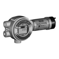
MSA Ultima XIR Installation & Maintenance Instructions Manual (142 pages)
Gas Monitors
Brand:
MSA
| Category:
Measuring Instruments
| Size: 1.7 MB
Table of Contents
Table of Contents
7
Chapter 1, Installation
14
General Description
14
Identifying Your Unit
14
Figure 1-1. General-Purpose Ultima XA Monitor
14
Figure 1-3. Explosion-Proof Ultima XIR Monitor
15
Figure 1-4. General-Purpose XA Remote Sensor Module
16
Figure 1-5. Explosion-Proof XE Remote Sensor Module
16
Figure 1-6. Explosion-Proof XIR Remote Sensor Module
17
Installing Your Gas Monitor
18
Installing the Ultima XA Gas Monitor
19
Installing the Ultima XE Gas Monitor
19
Figure 1-7. Ultima XE and XIR Mounting Bracket
20
Installing the Ultima XIR Gas Monitor
21
Figure 1-8. Ultima XIR
21
Electrical Connections for Ultima X Gas Monitors
22
Figure 1-9. Ultima XE Grounding Terminals
22
Table 1-1. Installation Outline Drawing List
23
Wiring for All Models
23
Table 1-2. Cable Length and Wire Size for Units Without
24
Use of External Controllers
25
Table 1-3. Installation Outline Drawings for Ultima X Power Supplies
25
Identify PCB Configuration
26
Figure 1-10. General-Purpose Two-Wire Operation
27
Figure 1-11. Explosion-Proof Two-Wire Operation
27
Figure 1-12. General-Purpose Three-Wire Operation
28
Figure 1-13. Explosion-Proof Three-Wire Operation
28
Figure 1-14. Two-Wire Printed Circuit Board
29
Figure 1-16. Three-Wire Printed Circuit Board
31
Installing the Ultima X Remote Sensor Module
33
Figure 1-18. Remote Module General-Purpose
33
Figure 1-19. Remote Module Explosion-Proof
33
Electrical Connections for Remote Sensors
34
Table 1-4. Remote Module Wiring and Placement
35
Table 1-5. Remote Sensor Wiring Cable
35
Table 1-6. Low Temperature Wiring Cable
35
Chapter 2
37
Start-Up and Calibration
37
Initial Start-Up
37
Figure 2-1. LCD Gas Concentration Display
37
Table 2-1. Instrument Operation
38
Calibration Basics
40
Figure 2-2. Ultima Calibrator
41
Figure 2-3. Ultima Controller
41
Figure 2-4. Ultima X Optional Push-Button Calibrator
41
Calibration Output Signal
42
Ultima Calibrator
42
Ultima Controller
42
Calibration Kit
43
Ultima X Series Gas Monitor Calibration Procedure
43
Equipment Required
44
Span Gas Values
45
Table 2-2. Factory-Set Span Values
45
Table 2-3. Calibration Guide for Combustible Gas Sensor
47
INITIAL Calibration
48
Standard Calibration
49
Figure 2-5. Apply ZERO Gas Flag
50
Figure 2-6. Apply SPAN Gas Flag
51
Figure 2-7. Calibration End Display
53
OXYGEN Calibration
54
XIR Calibration
54
Chapter 3, Specifications
56
Table 3-1. Performance Specifications
56
Table 3-2. Sensor Response to Interferants
59
Chapter 4, Maintenance
63
General
63
Table 4-1. Operational Display Messages
63
Table 4-2. Configuration Display Messages
64
Table 4-3. Troubleshooting Guidelines
64
Ultima XIR Cleaning Procedure
66
Replacing an Ultima XE or Ultima XA Sensor
67
Figure 4-1. "Change Sensor" Scrolls Across the Display
68
Figure 4-2. Sensor Assembly and Sensor Guard for General-Purpose Model
69
Obtaining Replacement Parts
70
Table 4-4. Replacement Parts
70
Appendix A, Optional Features
72
Internal Relays
72
General Information
72
Unpacking, Mounting and Wiring
72
Ultima X Series Gas Monitor Internal Relays
73
Relay Specifications
73
Table A-2. Relay Specifications
73
Alarm Relays
74
Fault Relay or Trouble
75
Figure A-1. Relay Contacts
75
Relay Connections
76
Figure A-2. Relay Printed Circuit Board
77
Optional RESET Push-Button
78
General
78
RESET Button Selection
78
Optional Push-Button Calibration
79
Table A-3. Push-Button Calibration
79
Optional Horn Relay Software
80
To Activate the Horn Relay
80
To Reset the Horn Relay
80
Appendix B
81
Calibration Guide for Additional XIR/XI Gases
81
Appendix C
83
General Certification Information
83
Appendix D, HART Specific Information
85
HART Field Device Specification
85
Table D-1. Device Identification
85
Host Interface
86
Table D-2. Current Values
86
Status Information
87
Extended Device Status
87
Table D-3. Device Variables Exposed by the Ultima Monitor
87
Table D-4. Dynamic Variable Implemented by Ultima Monitor
87
Table D-5. Additional Device Status (Command #48
88
Universal Commands
90
Common-Practice Commands
90
Burst Mode
90
Catch Device Variable
90
Table D-6. Supported Commands
90
Command #129: Read Sensor Gas Type
91
Table D-7. Device-Specific Commands
91
Command #130: Read Device Real Time Clock
92
Command #131: Read Alarm Setpoints
92
Command #132: Read Alarm Control Actions
93
Command #133: Read Min, Max, Avg Values
93
Command #134: Read Last Cal Date
94
Command #135: Read Gas Table
94
Command #136: Read Input Voltage Value
94
Command #137: Read Auto Zero Comp Value
95
Command #139: Read Sensor Status Message
95
Command #140: Read Swap Delay Status
95
Command #141: Read Cal Signal Status
96
Command #142: Read Alert Option Status
96
Command #143: Read Sensor Temperature
97
Command #144: Read Relay Normal State
97
Command #173: Write RTC
98
Command #174: Write Alarm Setpoints
99
Command #175: Write Alarm Setpoint Control Actions
100
Command #176: Write Average Interval
101
Command #177: Write Upper Trim Point
102
Command #178: Write Gas Table
103
Command #179: Write Sensor Data Sheet
104
Reset Control
104
Command #180: Write Sensor Swap Delay Enable
105
Command #181: Write Cal Signal Enable
106
Command #182: Write Calibration Mode
107
Command #183: Write Calibration Abort
108
Command #184: Write Calibration Step
109
Command #185: Write Alarm Acknowledge
110
Command #186: Write Protect Mode
111
Command #187: Write Alert Option
112
Command #188: Write Relay Normal State
113
Table D-10. Gas Table Values
114
Table D-8. Gas Type Descriptions
114
Table D-9. Alarm Control Actions
114
Table D-11. Calibration Modes
115
Table D-12. Sensor Status Codes
115
Performance
116
Power-Up
116
Reset
116
Self-Test
116
Table D-13. Sampling Rates
116
Busy and Delayed-Response
117
Long Messages
117
Non-Volatile Memory
117
Table D-14. Command Response Times
117
Modes
118
Write Protection
118
Damping
118
Capability Checklist
118
Table D-15. Capability Checklist
118
Calibration Using a HART® Communicator
119
Sensor Zero Selection Menu
119
Default Configuration
119
Table D-16. Default Configuration
119
Standard Zero/Span Calibration Selection Menu
121
Initial Calibration Procedures
124
User Calibration Selection Menu
124
Figure D-1. Zero Cal Step Screen
125
Figure D-2. Span Cal Step Screen
125
Figure D-3. Select Sensor Calibration
126
From the Sensor Trim Menu
126
Figure D-4. First Warning Screen
127
Figure D-5. Second Warning Screen
128
Figure D-6. Standard Calibration Function Select Screen
129
Figure D-7. Calibration Initiated Screen
130
Figure D-8. Selection Confirmation Screen
131
Figure D-9. Sensor Zero Countdown Screen
132
Figure D-10. Zero Adjustment Screen
133
Figure D-11. Span Countdown Screen
134
Figure D-12. Adjusting Span Screen
135
Figure D-13. Calibration Completion Message
136
Figure D-14. Calibration Gas Reminder Screen
137
Figure D-15. Loop Control Reminder Message
138
Figure D-16. Calibration Status Screen
139
Figure D-17. Sensor Trim Point Screen
140
Figure D-18. Additional Sensor Status Screen
141
Figure D-19. Device Status Screen
142
Advertisement
MSA Ultima XIR Instruction Manual (61 pages)
Gas Monitors
Brand:
MSA
| Category:
Monitor
| Size: 1.06 MB
Table of Contents
Table of Contents
5
Chapter 1 Installation
9
General Description
9
Identifying Your Unit
9
Installing Your Gas Monitor
11
Caution
11
Warning
11
Installing the Ultima XA Gas Monitor
12
Installing the Ultima XE Gas Monitor
12
Installing the Ultima XIR Gas Monitor
13
Warning
13
Caution
13
Electrical Connections for Ultima X Gas Monitors
14
Warning
14
Wiring for All Models
14
For Milliamp Output
15
Warning
15
Oxygen) Sensor, 4-20 Ma Signal Output (Two Wire Sensor)
15
Typical Ultima X Series Gas Monitor Wiring
16
Sensor)
16
And 4-20 Ma Signal Load
16
Installing the Ultima X Remote Sensor Module
20
Electrical Connections for the Ultima X Series Remote Sensor Module
20
Warning
20
Caution
20
At the Ultima X Series Remote Sensor Location
21
Start-Up and Calibration
23
Initial Start-Up
23
Caution
24
Calibration Basics
26
Caution
26
Non-Combustible Chemicals that Reduce Catalytic Sensor Sensitivity
26
Ultima Calibrator
27
Ultima Controller
27
Note on Resetting Latched Alarms with Controller or Calibrator
27
Ultima X Series Gas Monitor Calibration Output Signal
27
Calibration Kit
28
Ultima X Series Gas Monitor Calibration Procedure
28
INITIAL Calibration
28
Regular Calibration
29
Zeroing
29
Spanning
31
XIR Calibration
33
Warning
34
Calibration Documentation
34
Chapter 3 Specifications
35
Chapter 4 Maintenance
43
General
43
Ultima XIR Cleaning Procedure
43
Caution
44
Replacing an Ultima XE or Ultima XA Sensor
44
Warning
45
Caution
45
Obtaining Replacement Parts
48
Warning
49
Appendix A Internal Relay Option
50
General Information
50
Caution
50
Unpacking, Mounting and Wiring the Ultima X Series Gas Monitor with
50
Internal Relays
50
Ith Internal Relays (4-20 Ma Model
54
Ultima X Series Gas Monitor Internal Relays
55
Relay Specifications
55
Alarm Relays
56
Fault Relay or Trouble
57
Optional RESET Push-Button
58
General
58
RESET Button Selection
58
Optional Push-Button Calibration
59
Relay Connections
59
Warning
60
Advertisement
Related Products
MSA ULTIMA XL Series
MSA ULTIMA XT Series
MSA Ultima XA
MSA Ultima XE
MSA Ultima
MSA Ultima XI
MSA ULTIMA X-Series
MSA Ultima Series
MSA Ultima X Series
MSA Ultima X
MSA Categories
Safety Equipment
Respiratory Product
Security Sensors
Gas Detectors
Measuring Instruments
More MSA Manuals
Login
Sign In
OR
Sign in with Facebook
Sign in with Google
Upload manual
Upload from disk
Upload from URL