
Related Manuals for GE PACSystems RXi-XP IPC


Summary of Contents for GE PACSystems RXi-XP IPC
- Page 1 GFK-2990 PACSystems* RXi Box IPC-XP Hardware Reference Manual Edition 3.0 (HWRMRXiXP) Internal...
- Page 2 Document History Edition Description Date New document based on 042 Release 1.0 Typos corrected, product renamed, links to BIOS guide removed, Draft 1.0 2013-11-25 doubled tables removed, power consumption for new system configurations updated, CFAST Slot Type I specified First release, footer link to .docx file removed 2014-02-04 Including RXMxx0, RXM1x2 sheet metal cabinet and PERC01/02 riser 2015-06-05...
- Page 3 All computer code and software contained in this document is licensed to be used only in connection with a GE Intelligent Platforms hardware product. Even if this code or software is merged with any other code or software program, it remains subject to the terms and conditions of this license.
- Page 4 GNU Lesser General Public License (LGPL) (See chapter 9, Appendix). In accordance with LGPLv2.1 licensing, you may obtain the corresponding source code from GE Intelligent Platforms for a period of three years after our last shipment of this product, which will be no earlier than 2017. Please include the model and serial number of the product and direct requests to: oss@ge.com.
- Page 5 CE compliance and certify this to the end user. Where GE Intelligent Platforms supplies a complete/functional system for use by end users in EU countries a CE certificate will be cited in the manuals/documents which are provided with the products. The CE (and year of certification) symbol is shown on the equipment, typically on the type or S/N label or close to the power cable entry.
- Page 6 GE Intelligent Platforms, Inc. 2500 Austin Drive Charlottesville, VA 22911 U.S.A. Phone: +1-800-322-3616 Web: http://www.ge-ip.com/ Germany GE Intelligent Platforms GmbH & Co. KG GE Intelligent Platforms, Inc. Memminger Str. 14 2500 Austin Drive 86159 Augsburg Charlottesville, VA 22911 Germany U.S.A.
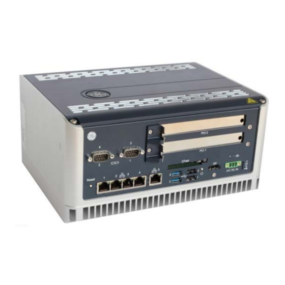
- Page 7 Welcome This document defines the RXi Box Industrial PC-XP composed of a bCOM6 COM Express module and the CEC02 or CEC04 Carrier board. A Computer-On-Module, or COM, is a module with all components necessary for a bootable host computer, packaged as a super component. A COM requires a Carrier Board to connect I/O and to power up. COMs are used to build modular solutions and offer OEMs fast time-to-market with reduced development cost.
- Page 8 (voltage close to 0 V) or the signal initiates actions on a high-to-low transition. • Text in Courier font indicates a command entry or output from a GE Intelligent Platforms embedded PC product using the built-in character set. •...
- Page 9 Please see chapter ʹSupport, Service, and Warranty Informationʹ for further details on repairs and product support. For support on the web and product information, visit our website at http://www.ge-ip.com/ PACSystems RXi Box IPC-XP Hardware Reference Manual GFK-2990 Internal...
-
Page 10: Table Of Contents
Table of Contents Introduction ..........................................15 PC Design .........................................15 Carrier Design ........................................15 COM Express Card Design ..................................17 Unpacking and Inspection ....................................19 Package Contents .......................................19 Available Accessories ....................................20 Hot Surface ........................................20 ESD ............................................21 Initial Inspection ......................................21 Unpacking ........................................22 Installation ..........................................23 Mounting instruction ....................................23 3.1.1 Flat wall mounting ....................................23 3.1.2 Slim Mounting ......................................27 Installation preparation ....................................29... - Page 11 ETHERNET ........................................53 PCIE ports ........................................54 PCI ROUTING ........................................54 Specifications ........................................... 57 RXi Box IPC-XP Specifications ................................57 Support, Service and Warranty ..................................61 Technical Support ....................................... 62 Support on the Web ....................................63 Warranty .......................................... 63 Error Report ........................................64 Glossary ............................................
- Page 12 List of Figures Figure 1: Packaging ..........................................22 Figure 2; Heat dissipation drawing ..................................23 Figure 3: Flat mounting with mounting plates ..............................24 Figure 4: Flat wall mounting through the box – illustration ........................25 Figure 5: Flat wall mounting through the wall – illustration ........................26 Figure 6: Clearances slim wall mounting –...
- Page 13 List of Tables Table 1: Order code and system combinations ............................... 15 Table 2: Delivery volume ....................................... 19 Table 3: Available accessories ....................................20 Table 4: Front Power LED ......................................42 Table 5: Hard disk activity LED ....................................42 Table 6: User status LED ....................................... 42 Table 7: Over temperature LED ....................................
- Page 14 PACSystems RXi Box IPC-XP Hardware Reference Manual GFK-2990 Internal...
-
Page 15: Introduction
1 Introduction Chapter Scope This chapter describes features, capabilities and compatibilities of the RXi Box IPC-XP, including the CEC02/CEC04 Carrier board and the bCOM6 module. 1.1 PC Design The RXi Box IPC-XP consists of a combination of the CEC02/CEC04 carrier board and the bCOM6 COM Express card, as well a PCI and/or PCI Express riser card and housing w/ heat sink. - Page 16 The COM Express Carrier CEC04, used in a RXE and the RXMxx0, provides the following core hardware and firmware resources: • Support for COM Express Module Type 6 • Functions available on internal connectors Mini PCIe slot half/full size Almost standard PCIe slot x4 for use with riser card 043/044 2 or 4 PCI slots half length, full height on riser card 043/044 SATA direct drive connect BR2032 Lithium Coin Battery...
-
Page 17: Com Express Card Design
1.3 COM Express Card Design The bCOM6 CPU modules are fully IBM-AT compatible stand-alone PCs. They are equipped with many functions in a very small form-factor. The following COM Express CPU modules are available: bCOM6L14: Processor ― Intel® Core™ i7-3555LE Processor 2.5GHz ―... - Page 18 PACSystems RXi Box IPC-XP Hardware Reference Manual GFK-2990 Internal...
-
Page 19: Unpacking And Inspection
2 Unpacking and Inspection Chapter Scope This chapter covers the suggested inspection and preparation considerations and background information necessary prior to using the RXi Box IPC-XP. Unpacking, initial inspection, and first-time operation of the RXi Box IPC-XP are covered. Following the procedures given in the chapter are recommended, and they will verify proper operation before the product is integrated into your system. -
Page 20: Available Accessories
10 pcs Slim 70 Mount Kits RXi Box IPC-XP Table 3: Available accessories NOTE Please contact the GE Intelligent Platforms sales department or your sales representative for latest information on options and accessories. NOTE Accessories are subject to change without notice. -
Page 21: Esd
If damage is observed (usually in the form of bent component leads or loose socketed components), contact GE Intelligent Platforms for additional instructions. Depending on the severity of the damage, it may necessary to return the product to the factory for repair. -
Page 22: Unpacking
Careful inspection of the shipping carton should reveal some information about how the package was handled by the shipping service. If evidence of damage or rough handling is found, you should notify the shipping service and GE Intelligent Platforms as soon as possible. Figure 1: Packaging NOTE Retain all packing material in case of future need. -
Page 23: Installation
3 Installation Chapter Scope This chapter covers the installation of the RXi Box IPC-XP and initial power-on operations. 3.1 Mounting instruction The IPC cooling is designed for wall mounted orientation of the box. The orientation of the heat sink fins depends on the order code. -
Page 24: Figure 3: Flat Mounting With Mounting Plates
Flat Mounting with Mounting Plates The choice of correct screws depends on the nature of the wall. The mounting plates have 4 drills holes with a diameter of 5.3 mm. So the maximum screw diameter cannot be higher than 5.2 mm. The head of the screws have to be smaller than 10 mm, to pass the hole of the top fixing points of the mounting plate. -
Page 25: Figure 4: Flat Wall Mounting Through The Box - Illustration
Flat wall mounting through the box The choice of correct screws depends on the nature of the wall. The box has 4 drills with a diameter of 5.1 mm. So the maximum screw diameter cannot be higher than 5 mm. Remove the front lid by opening the 4 screws with a screw driver (Torx-20). -
Page 26: Figure 5: Flat Wall Mounting Through The Wall - Illustration
Flat wall mounting through the wall To fix the IPC with screws from the wall side, you need drill holes in the wall. The positions for the holes can be taken from the drawing below. The thread in the housing is a M6 with a usable thread length of 15 mm. Choose the screw length so that a minimum of 10 mm thread will be used. -
Page 27: Slim Mounting
3.1.2 Slim Mounting Clearances slim wall mounting For heat dissipation observe the minimum clearances from the drawing below: Slim 80 mounting plate ACCMP01 Slim 70 mounting plate ACCMP03 ICRXI ICRXI Figure 6: Clearances slim wall mounting – illustration PACSystems RXi Box IPC-XP Hardware Reference Manual GFK-2990 Internal... -
Page 28: Figure 7: Slim Mounting With Mounting Plate
Slim Mounting with Mounting Plate The choice of correct screws depends on the nature of the wall. The mounting plate has 4 drills holes with a diameter of 4.5 mm. So the maximal screw diameter cannot be higher than 4.4 mm. The head of the screws have to be smaller than 10 mm, to pass through the hole of the top fixing points of the mounting plate. -
Page 29: Installation Preparation
3.2 Installation preparation Use the following steps to install your GE Intelligent Platforms hardware: WARNING Danger to life through electric shock! Before installing or removing any board, please ensure that the system power and external supplies have been turned off. -
Page 30: Required Items
3.4 Required items The following items are required to start the board in a standard configuration: 3.4.1 Power Supply Please refer to chapter ʹSpecificationsʹ for details. Make sure that the 24V supply is capable of meeting the total power requirements of the RXi Box IPC-XP. Please make sure that you do not have the power supply turned ON while opening the housing for installing add-on cards such as PCIe cards or internal SATA drives into the RXi Box IPC-XP. -
Page 31: Minimum System Requirements
3.5 Minimum System Requirements The RXi Box IPC-XP has been thoroughly tested, and is nearly ready for usage in the target system. In order to verify RXi Box IPC-XP operation for the first time, it is suggested that you only configure a minimal system. It is not necessary to have disk drives, a Flash disk or other accessories connected in order to perform the RXi Box IPC-XP POWER-ON-SELF-TEST (POST). -
Page 32: Installation Of A Pci Board
3.6 Installation of a PCI board ATTENTION The information described in this chapter is for service technician only! PCI Boards and PCI Express Boards are installed into the RXi Box IPC-XP as shown by the pictures below for the RXE2x0. All other configurations including RXM are quite similar in this procedure. Slot cover, empty Slot cover screw removed PCI support_B removed... -
Page 33: Figure 8: Installation Of A Pcie Card
PCI card bracket inserted into slot PCI card inserted into PCIe connector PCI support_B added PCI cover screw added Figure 8: Installation of a PCIe card PACSystems RXi Box IPC-XP Hardware Reference Manual GFK-2990 Internal... -
Page 34: Installation Of A Mini Pcie Add-On Card
3.7 Installation of a Mini PCIe add-on card ATTENTION The information described in this chapter is for service technician only! Mini PCIe cards are installed into the RXi Box IPC-XP by as shown: Mini PCIe slot full size, empty Mini PCIe slot half size, empty Insert Mini-PCIe module Mounted Mini-PCIe module Figure 9: Installation of Mini-PCIe module... -
Page 35: Installation Of An Internal Hard Disk Drive
3.8 Installation of an Internal Hard Disk Drive ATTENTION The information described in this chapter is for service technician only! A 2.5 inch drive bay within the RXi Box IPC-XP may be equipped with a standard SATA drive. The use of Solid State Drives is recommended. -
Page 36: Entering The Uefi Firmware Setup
If the RXi Box IPC-XP does not perform as described above, some damage may have occurred in shipping or chapter ʹSupport, Service, and Warranty Informationʹ for further instructions. the board is not installed or setup properly. Contact GE Intelligent Platforms technical support as described in 3.11 Exchange the Battery... -
Page 37: Figure 12: Removed Battery
3. Remove the RTC battery from the retaining clip. Figure 12: Removed battery WARNING Use of a different type of battery than that specified here may present a risk of fire or explosion! WARNING Battery may explode if mistreated. Do not recharge, disassemble, heat above 100°C or incinerate! 4. - Page 38 5. Remount the top cover on the IPC and tighten the four screws to secure it. PACSystems RXi Box IPC-XP Hardware Reference Manual GFK-2990 Internal...
-
Page 39: Hardware
4 Hardware Chapter Scope This chapter describes the hardware of the RXi Box IPC-XP. 4.1 Overview for RXE and RXMxx0 based on the carrier CEC04 Power DC-DC Conversion Conn Transc RS-232 Transc UART RS-232 4-ch mini PCI-e optional Transc x1 PCIe Gen1 Opto- RS-422/ coupl... -
Page 40: Overview For Rxm1X2 Based On The Carrier Cec02
4.2 Overview for RXM1x2 based on the carrier CEC02 Figure 15: Hardware Overview PACSystems RXi Box IPC-XP Hardware Reference Manual GFK-2990 Internal... -
Page 41: Interfaces
4.3 Interfaces Depending on the used carrier two basic variants of the front panel exist. Top is always shown the standard panel on a CEC04. Below can be found the panel of the CEC02 used in the RXM1x2. RXE and RXMxx0: Figure 16: front panel RXE and RXMxx0 RXM1x2: Figure 17: front panel RXM1x2... -
Page 42: Leds
4.3.1 LEDs The RXi Box IPC-XP has a set of status LEDs for indicating various functions. Figure 18: front panel LEDs Status. Some power is applied Valid power is applied, CPU is in any standby or off state amber Valid power, CPU is powered green Table 4: Front Power LED Status. -
Page 43: Power Button
4.3.2 Power Button There is a Power Button at the front panel. Please use an appropriate tool for operation when needed. Figure 19: Power button A short push of the power button triggers the operating system shutdown (Power State S5). If the operating system doesn’t react, holding the button pushed for more than 5 seconds forces the RXi Box IPC-XP to shut down immediately without operating system support. -
Page 44: Ethernet Interface (Eth1, Eth2, Eth3, Eth4, Eth5; On Rxm1X2 Eth1, Eth2, Eth3)
4.3.4 Ethernet Interface (Eth1, Eth2, Eth3, Eth4, Eth5; on RXM1x2 Eth1, Eth2, Eth3) Figure 21: Ethernet Interface The Ethernet interfaces require usage of CAT 5 cable for proper operation with 100/1000BaseT. Name 1000base Name 10/100base TxD+ LP_DA+ TxD- LP_DA- RxD+ LP_DB+ LP_DC+ LP_DC-... -
Page 45: Display Port Interface
4.3.5 Display Port Interface A Display Port provides signals for connecting either a suitable monitor or adaptor to lots of other display standards. Figure 22: Display Port Name TxD0+/- TxD1+/- TxD2+/- TxD3+/- 10/12 AUXSEL CLK/AUX+ DAT/AUX- HTPLG n.c. DP_VCC 2, 5, 8, 11, 16, 19 Table 10: Display Port signals DP_VCC is fused with 2 A, but for normal operation don’t exceed 1 A at this pin. -
Page 46: Vga Interface (Rxm1X2 Only)
4.3.6 VGA Interface (RXM1x2 only) A VGA port provides signals for connecting a suitable monitor. Figure 23: VGA interface Name RED1 GREEN1 BLUE1 VGA_VCC 1) VGA1_DDCData VGA1_HSYNC VGA1_VSYNC VGA1_DDCClock Table 11: VGA 1) VGA_VCC is fused with 2 A, but for normal operation don’t exceed 1 A at this pin. PACSystems RXi Box IPC-XP Hardware Reference Manual GFK-2990 Internal... -
Page 47: Usb 2.0 Connectors (Usb1-2; On Rxm1X2 Usb1-4)
4.3.7 USB 2.0 Connectors (USB1-2; on RXM1x2 USB1-4) Four USB channels are available at standard USB Type A connectors. Each pair of them is fused with 2 A, but for normal operation don’t exceed 0.5 A per connector. Figure 24: USB 2.0 connectors Name FUSE_VCC USB-... -
Page 48: Usb 3.0 Connectors (Usb 3,4; Not On Rxm1X2)
4.3.8 USB 3.0 Connectors (USB 3-4; not on RXM1x2) Four USB channels are available at standard USB Type A connectors. Each pair of them is fused with 2 A, but for normal operation don’t exceed 0.5 A per connector. The blue USB connector supports USB 3.0 when used with the bCOM6L14 CPU module. -
Page 49: Power Connector
The power input is secured with two 5A blow fuses. If the Input power exceeds the limits, these fuses will be blown to protect all circuitry within the RXi Box IPC-XP. Please contact GE Intelligent Platforms for a suitable replacement. -
Page 50: Internal Sata Slot
4.3.10 Internal SATA Slot Inside the RXi Box IPC-XP there is a bay for mounting a standard SATA 2.5 inch drive. NOTE Drives with rotating media may be used if they withstand the intended temperature range inside the RXi Box IPC-XP. The use of Solid State Disk is recommended. 4.3.11 CFast Slot On the front of the RXi Box IPC-XP there a CFast Type I flash slot is available. -
Page 51: Serial (Com1,2 Or Com1-4; Not On Rxm1X2) Ports
4.3.12 Serial (COM1,2 or COM1-4; not on RXM1x2) Ports (CP; Figure 28: Serial Ports – 2-Slot variant Figure 29: Serial Ports – 4-Slot variant The 2-slot variant of the RXi Box IPC-XP is provided with two serial ports. The two serial ports are RS232 on 9pin D-connectors for local terminals or peripheral communication. -
Page 52: Pcie Slots
4.3.14 PCIe Slots Depending on the system configuration there are up to two PCIe slots in the RXi Box IPC-XP. In a RXM1x2 the supported PCIe speed is 2.5GBit/s (Gen 1) and the link width is x4. In a RXx5 or RXx6 the supported PCIe speed is 5.0GBit/s (Gen 2) and the link width is x1 in Slot 1 and x2 in Slot 2. -
Page 53: Resources
5 Resources Chapter Scope This chapter lists the hardware and firmware resources of the CEC04 carrier and the bCOM6 module. 5.1 Programmable devices 5.1.1 SMBUS DEVICES Device Address Function PI6C20800S 1101 110x PCIe Clock Buffer on CEC04 DB106 1101 010x PCIe Clock Buffer on CEC02 (RXM1x2) LM29245 1001 100x... -
Page 54: Pcie Ports
5.3 PCIE ports The PCIe ports are provided by the COM Express Module. Following PCIe allocation is provided: COM Express Signal Device on CEC04 Device on CEC02 (RXM1x2) Description PEG_T/RX[3..0]+/- 5 port PCIe Switch to PCIe slot x4 PCIe port x4 lane Ethernet Controllers PCIE_T/RX[0]+/- PCIe slot for riser card... -
Page 55: Table 19: Pci Routing
Function Connected to Vendor Device Bus/Dev/Func Ether #4 front 8086 1533 3/00/0 Ether #3 front 8086 1533 4/00/0 Ether #2 front 8086 1533 5/00/0 Ether #1 front 8086 1533 6/00/0 PCIe Serial Serial 12D8 7954 9/00/0 Mini PCle A/00/0 On Riser card 043/044 (RXx2x0, RXx4x0) PCIe to PCI bridge PCI Slots... - Page 56 PACSystems RXi Box IPC-XP Hardware Reference Manual GFK-2990 Internal...
-
Page 57: Specifications
6 Specifications Chapter Scope This chapter gives some useful information when using an RXi Box IPC-XP for the first time. It might be also useful to read this chapter carefully, when problems came up in using the RXi Box IPC-XP. 6.1 RXi Box IPC-XP Specifications Temperature Ambient temperatures and humidity values for the RXi Box IPC-XP:... -
Page 58: Table 23: Input Power
Humidity • Operating: 10 % to 95 % rH, non-condensing Power Entry The RXi Box IPC-XP works from a single main power rail with a nominal value of +24V (+/-10 %). The nominal voltage should be 24Vdc, SELV according to IEC60950-1. Nominal Input Input Range Max. - Page 59 Power Budget for add-on devices The CEC02 and CEC04 support a power budget for USB devices, SATA devices and add-on cards of total 25W. For the add-on cards on the riser card any share between +12V, 5V and 3.3V power consumption is possible up to 20W maximum for all two/four cards together.
- Page 60 PACSystems RXi Box IPC-XP Hardware Reference Manual GFK-2990 Internal...
-
Page 61: Support, Service And Warranty
GE Intelligent Platforms GmbH & Co. KG Memminger Str. 14 Augsburg, D-86 159 Germany GE Intelligent Platforms, Inc. uses two regional headquarters for the purpose of support, service, RMA returns and other functions. Regional areas: world-wide Europe, Russia, Near East, India, Africa Americas &... -
Page 62: Technical Support
7.1 Technical Support If you should have a problem with a GE Intelligent Platforms product: Free technical support is available by phone, fax or email. Telephone support is available at main locations or at the regional center where the product was bought. -
Page 63: Support On The Web
7.2 Support on the Web For support and information, visit our website at http://www.ge-ip.com/ Information for components, corresponding driver software, etc. can also be found at the following locations: AMD Corp. www.amd.com American Megatrends www.ami.com Fedora www.fedora.redhat.com IBM Corp. www.ibm.com Intel Corp. -
Page 64: Error Report
7.4 Error Report For error reports and RMA (Return Material Authorization) forms contact support at these email addresses: repairs.augsburg.ip@ge.com In case of difficulties provide at least the information listed below to an appropriate support center or on their web site as listed above: •... -
Page 65: Glossary
8 Glossary APIC Advanced Programmable Interrupt Controller Built-In Test Conformite Europeenne (European conformity) CFast A variant of CompactFlash. CFast supports a higher maximum transfer rate than current Compact Flash cards. Computer On Module Digital Video Interface Error Correction Checking EEPROM Electrically Erasable Programmable Read-Only Memory Electro-Magnetic Interference Electro-Static Discharge... - Page 66 PACSystems RXi Box IPC-XP Hardware Reference Manual GFK-2990 Internal...
-
Page 67: Appendix
9 Appendix GNU LESSER GENERAL PUBLIC LICENSE Version 3, 29 June 2007 Copyright © 2007 Free Software Foundation, Inc. <http://fsf.org/> Everyone is permitted to copy and distribute verbatim copies of this license document, but changing it is not allowed. This version of the GNU Lesser General Public License incorporates the terms and conditions of version 3 of the GNU General Public License, supplemented by the additional permissions listed below. - Page 68 3. Object Code Incorporating Material from Library Header Files. The object code form of an Application may incorporate material from a header file that is part of the Library. You may convey such object code under terms of your choice, provided that, if the incorporated material is not limited to numerical parameters, data structure layouts and accessors, or small macros, inline functions and templates (ten or fewer lines in length), you do both of the following: a) Give prominent notice with each copy of the object code that the Library is used in it and that the...
- Page 69 Lesser General Public License shall apply, that proxy's public statement of acceptance of any version is permanent authorization for you to choose that version for the Library. GE Intelligent Platforms Additional Resources © 2013 - 2016 GE Intelligent Platforms Embedded Systems, Inc. All rights reserved. Information Centers For more information, please visit the...
Need help?
Do you have a question about the PACSystems RXi-XP IPC and is the answer not in the manual?
Questions and answers