Table of Contents
Advertisement
Quick Links
Advertisement
Table of Contents
Troubleshooting

Related Manuals for Advantech B+B SmartWorx IMcV-Giga-FiberLinX-III


Summary of Contents for Advantech B+B SmartWorx IMcV-Giga-FiberLinX-III
- Page 1 IMcV-Giga-FiberLinX-III USER MANUAL...
- Page 2 Advantech B+B SmartWorx - Americas 707 Dayton Road Ottawa, IL 61350 USA Phone (815) 433-5100 (815) 433-5105 Advantech B+B SmartWorx - Europe Westlink Commercial Park Oranmore, Co. Galway, Ireland Phone +353 91-792444 Fax +353 91-792445 www.advantech-bb.com support@advantech-bb.com...
-
Page 3: Table Of Contents
iMcV-Giga-FiberLinX-III CONTENTS Chapter 1: About iMcV-Giga-FiberLinX-III ..........5 Port Interfaces ......................6 Management ........................ 6 Chapter 2: Installation Instructions ............7 DIP Switch Selectable Mode Configuration ..............7 DIP Switch Settings ....................7 Host/Remote and Standalone Units ................8 LoSPD .......................... 8 Mini-Serial Port ...................... - Page 4 iMcV-Giga-FiberLinX-III Appendix A: iView Management software ..........43 iView (iConfig view) ....................43 Using iView ........................ 43 Appendix B: Pinouts ................60 RJ-45 Data Port Pinout....................60 RS-232 Serial Console Port ..................60 Appendix C: Troubleshooting ..............61 Appendix D: Unified Management Agent (UMA) ........62 Appendix E: Glossary ................
-
Page 5: Chapter 1: About Imcv-Giga-Fiberlinx-Iii
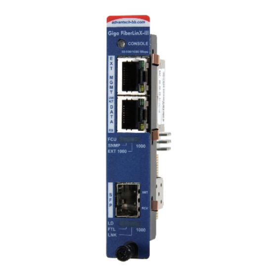
iMcV-Giga-FiberLinX-III CHAPTER 1: ABOUT IMCV-GIGA-FIBERLINX-III The iMcV-Giga-FiberLinX-III allows network operators to deploy managed Ethernet services with a full range of remote management, traffic monitoring, and alarm reporting features. The single-wide module offers two fixed 10/100/1000Mbps copper ports and one fiber port in a fixed transceiver in a variety of wavelengths. -
Page 6: Port Interfaces
iMcV-Giga-FiberLinX-III PORT INTERFACES Every iMcV-Giga-FiberLinX-III includes the following ports: • A 10/100/1000 twisted pair (RJ-45) port (EXT MGMT) for management One of the following ports: • One fixed 1000 Mbps Fiber port • SFP port capable of receiving a Gigabit or 100Mbps fiber optic SFP module, or a Gigabit twisted pair (RJ-45) SFP module DATA port: •... -
Page 7: Chapter 2: Installation Instructions
iMcV-Giga-FiberLinX-III CHAPTER 2: INSTALLATION INSTRUCTIONS Each iMcV-Giga-FiberLinX-III module requires one slot in an iMediaChassis, MediaChassis or IE-MediaChassis. To install the module in a chassis, remove the blank faceplates covering the slots where the module is to be installed. Then slide the module into the chassis card guides until the module is seated securely in the connector. -
Page 8: Host/Remote And Standalone Units
iMcV-Giga-FiberLinX-III Switch Function Default Setting Management on EXT MGMT port Management on DATA port Management on OPTICS or UPLINK port Factory use – Do not change Factory use – Do not change LoSPD SFP If the model is 1x9, LoSPD is not functional, Remote Module Host Module HOST/REMOTE AND STANDALONE UNITS... -
Page 9: Chapter 3: Configuration
iMcV-Giga-FiberLinX-III CHAPTER 3: CONFIGURATION SOFTW ARE CONFIGURATION The following sections describe the features that can be configured. ASSIGNING IP INFORMATION When the iMcV-Giga-FiberLinX-III is installed in an iMediaChassis, use UMA to manage the iMcV-Giga-FiberLinX-III without an IP address. (Refer to the iView² online help for more information on UMA.) When the iMcV-Giga-FiberLinX-III is not installed in an iMediaChassis, SNMP management is not accessible until the iMcV-Giga-FiberLinX-III IP information (e.g., IP address, subnet mask, etc.) is... -
Page 10: Selective Advertising
iMcV-Giga-FiberLinX-III SELECTIVE ADVERTISING Selective Advertising, when used in combination with Auto Negotiation, advertises only the configured speed and duplex mode for the twisted-pair port. If a specific speed and/or duplex are desired, B+B SmartWorx recommends using Selective Advertising(rather than Force Mode) when connecting to devices that only use Auto Negotiation. - Page 11 iMcV-Giga-FiberLinX-III The menu of choices in the CLI includes: • No loopback, normal traffic mode • Loopback Enabled • Loopback, Source/Destination address swap • Loopback, address swap and clear Multicast bit • No learning on fiber or Data ports The menu of choices in iView² includes: •...
- Page 12 iMcV-Giga-FiberLinX-III HOST: NO LEARNING ON OPTICS & DATA PORTS The Loopback feature can be set to disable address learning on the OPTICS (or UPLINK) and DATA ports, allowing the loopback to be performed without interference from MAC address filtering functions. This is a function on the HOST unit.
-
Page 13: Configuration Options
iMcV-Giga-FiberLinX-III CONFIGURATION OPTIONS iMcV-Giga-FiberLinX-III includes features that are configurable via a serial/Telnet session (CLI) or through iView² (SNMP Management view; iConfig view). The following options are configurable through both the iView (iConfig view) and/or Serial/Telnet. Feature iView² Serial/Telnet Loopback ... -
Page 14: Basic Device Configuration Using The Cli
iMcV-Giga-FiberLinX-III BASIC DEVICE CONFIGURATION USING THE CLI After running through an initial self-test, the screen will display the following message: Press Enter for Device Configuration. Press Enter to open the main configuration screen. This screen allows the user to set the IP address and destination IP address for traps with the community string, read/write access and password as usual. - Page 15 iMcV-Giga-FiberLinX-III SAVED AND CURRENT VALUES Saved values display the changes made during the current session and current values display the values currently in use: • IP Address (IP address of SNMP agent) • Subnet Mask (mask to define IP subnet to which agent is connected) •...
- Page 16 iMcV-Giga-FiberLinX-III PASSWORD PROTECTION FOR SERIAL PORT CONNECTIONS Password/username is not offered for the serial port by default. This allows the end user to quickly access the device for basic configuration capability. Password protection is provided for the serial configuration process by pressing P on the main configuration screen.
- Page 17 iMcV-Giga-FiberLinX-III CREATING COMMUNITY STRINGS Community strings add a level of security to a network. The default community string is named "public" and has read/write access. For security, "public" should be replaced with custom community strings such as ones created with read-only access (for general use), and another with read/write access (for administrator).
-
Page 18: Commands List (Space Bar)
iMcV-Giga-FiberLinX-III DHCP DISABLE (STATIC IP ADDRESSING) DHCP is disabled in the default configuration. Initially, modules are assigned a Static default IP Address of 10.10.10.10. Changes to the Static IP Address can be added manually through iView (iConfig view), an RS-232 serial session, or a Console session. The changes will be initiated following reboot of the module. - Page 19 iMcV-Giga-FiberLinX-III Command Description cleandb Reboots the unit with a clean database. This removes all information from the database and sets the unit to factory defaults. download Downloads firmware via the TFTP protocol. accounts Allows the addition for User, Operator, Admin. vlan Provides selection of three modes of operation to support all VLAN configurations.
- Page 20 iMcV-Giga-FiberLinX-III The TFTP server should be open. Press Enter to start downloading the file. After the transfer process is complete, press Enter to load the configuration file: Once loaded into the device's SNMP memory area, the system prompts the user to reboot the device to make the new configuration active.
- Page 21 iMcV-Giga-FiberLinX-III OPERATIONAL MODE CONFIGURATION There are three modes of operation that can be configured through the Serial/Telnet session: Mode 1, supports a mixture of tagged and untagged traffic; Mode 2 Extra tagging; and Mode 3, VLAN Filter. OPERATION MODE 1 – MIXED TAGGED & UNTAGGED FRAMES In this mode, all tagged and untagged frames pass on any given port.
- Page 22 iMcV-Giga-FiberLinX-III OPERATION MODE 2 PORT BASED XTRA TAGGING Any port can be configured for extra tags on the frames. Press the down arrow on the computer keyboard to access the additional configuration commands.
- Page 23 iMcV-Giga-FiberLinX-III By default, the device is set up to access ports. However, one must be configured to be a trunk port.
- Page 24 iMcV-Giga-FiberLinX-III The Optics port and the Data port can be configured as an access port or a trunk port. When configuring as a trunk port, an Ethertype can be user-defined (a trunk port is also defined as a provider port, based on 802.1ad). If an Ethertype value comes in a trunk port and is different than the user-defined Ethertype, it will be treated as an unrecognized VLAN tagged frame.
- Page 25 iMcV-Giga-FiberLinX-III NOTE: It is strongly recommended that customers configure modules to segregate management traffic from data traffic. This is accomplished by assigning VLAN IDs. If the traffic is not segregated, any tests performed may not get the expected result. By segregating the types of traffic, the management network is secured from the customer’s network.
- Page 26 iMcV-Giga-FiberLinX-III BANDWIDTH (BW) Displays settings for Bandwidth configuration. OPTICS PORT Ingress Bandwidth Monitors the traffic entering the unit (ingress), discarding traffic that exceeds a fixed Committed Information Rate (CIR) Limit (CIR) plus Burst Allocation (BA). Frames are not held in queue - they either meet the bandwidth limits and are accepted into the unit, or they are dropped.
- Page 27 iMcV-Giga-FiberLinX-III DATA PORT Monitors the traffic entering the unit (ingress), discarding Ingress Bandwidth traffic that exceeds a fixed Committed Information Rate (CIR) Limit (CIR) plus Burst Allocation (BA). Frames are not held in queue - they either meet the bandwidth limits and are accepted into the unit, or they are dropped.
- Page 28 iMcV-Giga-FiberLinX-III used when a relationship to the actual customer data or line payload is required. If a 10 Mbps customer file needs to be sent in one second, then a minimum bandwidth limit of 10Mbps would need to use Layer 3 counting to allow this.
- Page 29 iMcV-Giga-FiberLinX-III SYSTEM DESCRIPTION (SYSDESCR) The sysDescr allows the end-user to enter a description for the B+B SmartWorx device. Within the iView² GUI, a name or some kind of identifier can be entered into the text box labeled Description. Once that description is saved, the identifier will be maintained, even if power is interrupted to the unit.
- Page 30 iMcV-Giga-FiberLinX-III (OPERATION AND ADMINISTRATION MANAGEMENT) OAM Two modes of operations control the OAM function:Passive and Active. Passive mode is the default mode. OAM Enable is defaulted to Enable. OAM AH passive/active is available on the fiber SFP ports and TX ports. •...
- Page 31 iMcV-Giga-FiberLinX-III UNIT Unit FlowControl displays the following screen:...
-
Page 32: Port Configuration (Port)
iMcV-Giga-FiberLinX-III Unit Enable/Disable FlowControl functionality on the unit. This must be enabled for FlowControl to function on any of the ports. FlowControl Unit Optics There are five selections to determine connectivity over the fiber run. Loopback Unit Max Choose from three selections of frame sizes. Framesize Boot Trap When connected to a switch, such as a Cisco switch, there is a... - Page 33 iMcV-Giga-FiberLinX-III The Port screen contains the following commands: Port Enable/Disable the port. (Select Enable to enable the port.) Enable Admin Set Administration status. (Select UP to enable/disable management through the port.) Status Both settings must be enabled to enable the port. Port Set the port manually or for Auto Negotiation for Twisted Pair ports.
-
Page 34: Configuration File Save / Restore Function
iMcV-Giga-FiberLinX-III LINK FAULT PASS THROUGH (LFPT) Link Fault Pass-Through (LFPT) is a diagnostic feature that can be enabled or disabled. When enabled, it allows the end user to visually detect that the Link and its associated LEDS on the front faceplate of the module are not lit when a fault occurs. -
Page 35: Saving A Configuration File To Disk
iMcV-Giga-FiberLinX-III SAVING A CONFIGURATION FILE TO DISK: From the Administration Tab in iView (iConfig view) click the Save Configuration button: Save Configuration screen. The user is prompted for a filename: Save As screen. The user is prompted to enter any notes to the header of the saved file for future reference when uploading the file through iView (iConfig view): Configuration Notes screen. -
Page 36: Uploading Saved Configuration File Through Iview (Iconfig View)
iMcV-Giga-FiberLinX-III After the file transfer from the device to disk, the user is notified of the status: Configuration Saved screen. UPLOADING SAVED CONFIGURATION FILE THROUGH IVIEW (ICONFIG VIEW ) From the Administration Tab in iView (iConfig view) click the Upload Configuration button: Upload Configuration screen. - Page 37 iMcV-Giga-FiberLinX-III By design, the IP Address configuration currently on the device is kept intact and not overwritten by the new configuration file.
-
Page 38: Chapter 4: Operation & Considerations
iMcV-Giga-FiberLinX-III CHAPTER 4: OPERATION & CONSIDERATIONS Before using iMcV-Giga-FiberLinX-III, decide the following: • Will iMcV-Giga-FiberLinX-III units be located at only one or at both ends of the fiber? • How will the iMcV-Giga-FiberLinX-III units be managed? • Will VLAN IDs be defined? HOW MANY iMcV-GIGA-FIBERLINX-III UNITS WILL BE USED? •... -
Page 39: Chapter 5: Led Operation
iMcV-Giga-FiberLinX-III CHAPTER 5: LED OPERATION The iMcV-Giga-FiberLinX-III features diagnostic LEDs as shown below. TX/FX LEDS Diagnostic LEDs Optics Port LEDs FCU (Far CPU Up): • Host: Glows green Glows green when “light” is when far end is detected on fiber input. detected. -
Page 40: Tx/Sfp Leds
iMcV-Giga-FiberLinX-III TX/SFP LEDS Diagnostic LEDs Optics Port LEDs FCU (Far CPU Up): • Host: Glows green • Glows green when when far end is “light” is detected on detected. fiber input. • Remote: Glows green when unit is FTL: configured as •... -
Page 41: Chapter 6: Troubleshooting
iMcV-Giga-FiberLinX-III CHAPTER 6: TROUBLESHOOTING • If two iMcV-Giga-FiberLinX-III Host/Remote units are not communicating properly, make sure one is a Host and the other is a Remote. If the second unit is not configured as a Remote, it will be recognized as a Standalone unit and the Host and Remote units will not communicate with each other properly. -
Page 42: The Agent Info Screen
iMcV-Giga-FiberLinX-III • Ensure READ/WRITE Community Strings for iMcV-Giga-FiberLinX-III and iView² are the same. • Ensure none of the twisted-pair ports on the iMcV-Giga-FiberLinX-III are connected to the twisted-pair port on the Management Module in an iMediaChassis series chassis. THE AGENT INFO SCREEN Information about the SNMP Agent software managing the iMcV-Giga-FiberLinX- III is contained on this screen. -
Page 43: Appendix A: Iview Management Software
iMcV-Giga-FiberLinX-III APPENDIX A: IVIEW M ANAGEMENT SOFTWARE iView² is the management software that features a Graphical User Interface (GUI) and gives network managers the ability to monitor and control the manageable B+B SmartWorx products. iView² is available in several versions: including a WebServer version 3.0, and can also function as a snap-in module for HP OpenView Network Node Manager and other third party SNMP Management software. - Page 44 iMcV-Giga-FiberLinX-III iView main screen. The following functions can be performed via iView Function Description Unit Display/modify unit information. Configuration Port Display/modify port data. Configuration Bandwidth Displays settings for bandwidth configuration, Tables Display statistics tables, including Unit and Port tables, RMON statistics, MIB-II ifTable and SFP Info. VLAN Provides configuration for VLAN IDs per port, Advanced...
- Page 45 iMcV-Giga-FiberLinX-III Host Configuration screen. Remote Configuration screen.
- Page 46 iMcV-Giga-FiberLinX-III BANDWIDTH Select Bandwidth to display configured bandwidth settings for the DATA or the Optics port. Bandwidth Configuration screen. TABLES Select tables to display a screen on which you can extract SFP information, RMON statistics, Unit and Port Tables, or MIB-II ifTable.
- Page 47 iMcV-Giga-FiberLinX-III Tables main screen. Select Unit and Port Tables to display the following information: link status (if the port is enabled/disabled), SNMP status, speed status on each port and other vital statistics. Unit and Port Tables screen.
- Page 48 iMcV-Giga-FiberLinX-III VLAN Enter a VLAN ID between 1 and 4094; possible priority settings are 0 (lowest priority) through 7 (highest priority). VLAN Configuration screen - showing Operation Mode 1. VLAN Configuration screen - showing Operation Mode 2.
- Page 49 iMcV-Giga-FiberLinX-III NOTE: VLAN configuration only applies to the Host. The Remote unit must be accessed directly via a separate IP address or through Telnet VLAN Configuration screen showing Operation Mode 3. ADVANCED Select Advanced button to refresh the module, view the speed of the link partners, upgrade a Host/Remote unit and reset the Host or Remote or set the Boot Trap Delay.
- Page 50 iMcV-Giga-FiberLinX-III OAM AH Select OAM AH to display the following screen and monitor the status, configuration, loopback, event log and statistics: OAM AH screen. From the above screen, select Configuration to display state and event configuration information as well as OAM supported functions: OAM AH: Configuration screen.
- Page 51 iMcV-Giga-FiberLinX-III LOOPBACK TESTING The iMcV-Giga-FiberLinX-III includes Loopback testing functionality. This feature is selectable via iView within the OAM AH configuration. The menu of choices for all ports includes: • Terminate/initiate • Process/ignore OAM Loopback is controlled by using the “Loopback” and “Ignore Rx” control parameters.
- Page 52 iMcV-Giga-FiberLinX-III Select Event Log to display the OAM event log showing fault changes that have occurred via OAM configuration: OAM AH: Event Log screen. The OAM Event Log table displays a history of the threshold crossing events and non-threshold crossing events that have occurred at the Ethernet OAM AH Level. There is a maximum of 8 events that can be displayed.
- Page 53 iMcV-Giga-FiberLinX-III OAM CFM Select OAM CFM to display the following screen and perform administrative control for Maintenance Domains (MDs), Maintenance Assocations (MAs) and Maintenance Association End Points (MEPs). The page contains a list of the local MEPs and provides menu controls to access the administrative functions associated with Create, Delete, and List MD, MA, and MEP information.
- Page 54 iMcV-Giga-FiberLinX-III For the first-time configuration, the user must first create an MD, then an MA, then local and peer MEPs can be added. To create an MD, select the "Configure MD' button to display the OAM CFM Maintenance Domain Configuration page as shown below: OAM CFM: Maintenance Domain Configuration screen.
- Page 55 iMcV-Giga-FiberLinX-III For the first configuration, create an MA after the MD. Select "Configure MA" to display the OAM CFM Maintenance Association Configuration screen as shown below: OAM CFM: Maintenance Association Configuration screen. NOTE: iView will automatically display this page if there is no MD yet defined when the user attempts to access any other menu control.
- Page 56 iMcV-Giga-FiberLinX-III For a first time configuration, the next step is to create a MEP. Select Add New MEP to display the OAM CFM MEP configuration page as shown below: OAM CFM: MEP Configuration screen. Select the MD, MA, enter the MEP ID, select the appropriate type, port and direction, and select the Primary VID, if applicable.
- Page 57 iMcV-Giga-FiberLinX-III Once the user has configured the MD, MA and at least one MEP, a particular instance of an MEP can be accessed for more detailed configuration. To access a particular instance of an MEP, click on the row containing the desired MEP as shown below: OAM CFM: MEP Configuration screen: MEP selected.
- Page 58 iMcV-Giga-FiberLinX-III The MEP Instance Configuration page offers more details about an individual MEP as shown below: OAM CFM: MEP Instance Configuration screen. From this screen, the user can perform the following functions: Function Description Continuity Enable/disable CCMs and verify the number of CCMs that have been sent.
- Page 59 iMcV-Giga-FiberLinX-III OAM CFM: Data Analysis screen. AGENT INFO Select Agent Info to display agent data: Agent Info screen.
-
Page 60: Appendix B: Pinouts
iMcV-Giga-FiberLinX-III APPENDIX B: PINOUTS RJ-45 DATA PORT PINOUT The following table lists the pin configuration for the RJ-45 Data connector. Signal Name Signal Direction 1000M 10/100M TXD1+ Out* TXD1- Out* RXD2+ Pin 1 RXD2- NOTE: The MDI/MDIX function will automatically adjust the direction of these signals to match the connected unit when running 10/100Base-T. -
Page 61: Appendix C: Troubleshooting
iMcV-Giga-FiberLinX-III APPENDIX C: TROUBLESHOOTING If a fiber connection cannot be established, perform the following to make sure that the fiber transceivers on the iMcV-Giga-FiberLinX-III are not over/under driving the fiber receivers: Make sure the fiber wavelength on both connected devices match (i.e. both are 1310 nm single-mode fiber). -
Page 62: Appendix D: Unified Management Agent (Uma)
iMcV-Giga-FiberLinX-III APPENDIX D: UNIFIED M ANAGEMENT AGENT (UMA) UMA operates in conjunction with B+B SmartWorx devices with on-board intelligence (e.g., the iMcV-Giga-FiberLinX-III and the iMediaChassis series. For example, install 20 devices in the chassis at the Central Office (CO), then connect each to a remote iMcV-Giga-FiberLinX-III unit installed at the customer's premise (CPL). -
Page 63: Appendix E: Glossary
iMcV-Giga-FiberLinX-III APPENDIX E: GLOSSARY Term/Acronym Definition 802.1ag IEEE standard for end-to-end OAM. 802.3ah IEEE standard addressing Ethernet in the first mile and also OAM for point-to-point Ethernet links. Connectivity Fault Management. Command Line Interface - An interface screen used for system management and diagnostics requiring the user to type commands rather than use a GUI. - Page 64 iMcV-Giga-FiberLinX-III Term/Acronym Definition MDI/MDIX Media-Dependent Interface/ Media-Dependent Interface Crossover - ability of an Ethernet port to automatically detect and configure its cabling connections to accommodate crossover or non- crossover wiring, depending on its link partner and cabling. Maintenance Association End Points. Management Information Base -A database of objects that can be monitored by a network management system.
-
Page 65: Specifications
iMcV-Giga-FiberLinX-III SPECIFICATIONS Environmenta Operating temperature range: 0 to +50 °C (+32 to +1 °F) Humidity: 5 to 95%, non-condensing Altitude: 0 to 10000 ft. Storage Temperature: -25 to +70 °C (-13 to +158 °F) Power Power Consumption (Typical): 850mA @ 3.6V DC (maximum) Standards / •... -
Page 66: B+B Smartworx Technical Support
USA/Canada: 1 (800) 346-3119 (Ottawa IL USA) Europe: +353 91 792444 (Ireland / Europe) Email: support@advantech-bb.com Web: www.advantech-bb.com STATEMENTS, PRECAUTIONS, GUIDELINES, REGULATORY FCC RADIO FREQUENCY INTERFERENCE STATEMENT This equipment has been tested and found to comply with the limits for a Class A computing device, pursuant to Part 15 of the FCC Rules. -
Page 67: Electrostatic Discharge (Esd) Precautions
iMcV-Giga-FiberLinX-III ELECTROSTATIC DISCHARGE (ESD) PRECAUTIONS This is an Electrostatic Sensitive Device. Use ESD precautions for safe handling. Before removing the card from the anti-static protective packaging: • Discharge any static electricity buildup on your body by touching a large grounded metal surface or the metal chassis on equipment connected to earth ground by a 3-wire power cord. -
Page 68: Regulatory, Standards, Compliances
© 2018 B+B SmartWorx – powered by Advantech. All rights reserved. The information in this document is subject to change without notice. B+B SmartWorx assumes no responsibility for any errors that may appear in this document.
Need help?
Do you have a question about the B+B SmartWorx IMcV-Giga-FiberLinX-III and is the answer not in the manual?
Questions and answers