
Related Manuals for Ahlborn ALMEMO 5690-2M


Summary of Contents for Ahlborn ALMEMO 5690-2M
- Page 1 ____________________________ Operating instructions english Data acquisition system ® ALMEMO 5690-2M V4.1 15/03/2013 www.ahlborn.com...
-
Page 2: Operating Controls
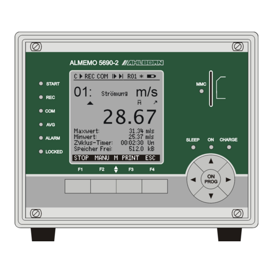
1. Operating controls 1. OPERATING CONTROLS 1.1 Front panel (1) LCD (2)Check lamps Status bar Device is on. Measuring point scan Cont SLEEP Flashes in sleep mode. Start / stop measuring © , ll CHARGE Battery is being charged. Record to memory Goes out as soon as fully Measured value output charged. -
Page 3: Rear
Rear 1.2 Rear (5) Module AP rechargeable (f) Output sockets A1, A2 battery (option) A1 Interface / optic fiber (ZA1909-DK5/L) RS 422 (ZA 5099-NVL/NVB) (a) Connection socket DC-A 12V Ethernet (ZA 1945-DK) Mains adapter (ZB 1212-NA9, 12V, 2.5A) Bluetooth (ZA 1709-BTx) (b) Check lamps A2 Network cable (ZA1999-NK5/NKL) DC-A... - Page 4 1. Operating controls Extension of measuring points with selector switch boards (7) Module U-A10: selector switch board 10 ALMEMO sockets (j) Measuring inputs 0 to 9 x0 to x9 for all ALMEMO sensors x+10 to x+39 max. 30 additional channels (k) Code switch M: measuring point x: 10 to 90...
-
Page 5: Table Of Contents
4. SAFETY INSTRUCTIONS................10 4.1 Special notes on use.................11 4.2 Handling batteries / rechargeable batteries correctly....11 5. INTRODUCTION ..................12 5.1 Functions of the ALMEMO 5690-2M ..........12 5.1.1 Sensor programming..............13 5.1.2 Measuring operations ..............14 5.1.3 Process control .................15 6. INITIAL COMMISSIONING ..............17 7. - Page 6 2. Contents 10.5 Data input ..................29 11. MEASURING WITH THE MEASURING MENUS ........30 11.1 Measuring with a measuring point ..........31 11.1.1 Selecting a measuring point ............31 11.1.2 Peak value memory with date and time-of-day .......31 11.2 Measured value correction and compensation ......32 11.2.1 Set measured value to zero ............32 11.2.2 Zero-point adjustment .............33 11.2.3 Sensor adjustment for chemical sensors and probes ....33...
- Page 7 Contents 12.1.3 Measuring rate, continuous measuring point scan....54 12.1.4 Start time Start date End time End date Measuring duration. . .55 12.2 Measured value memory ...............56 12.2.1 Memory with memory card............56 12.2.2 Measured data, recording............57 12.2.3 Numbering of measuring operations........58 12.2.4 Starting and stopping measuring operations......58 12.2.5 Scanning mode................58 12.2.6 Memory output.................60...
-
Page 8: General
2. Contents 12.7 Power supply menu................81 12.8 Locking, calibration menu (option KL)..........81 13. TROUBLE-SHOOTING ................83 14. DECLARATION OF CONFORMITY............84 15. APPENDIX....................85 15.1 Technical data ................85 15.2 Index....................87 15.3 Your contact person...............93 3. GENERAL Congratulations on your purchase of this new and innovative ALMEMO ®... -
Page 9: Scope Of Delivery
Scope of delivery 3.2 Scope of delivery When you unpack the device check carefully for any signs of transport damage and that delivery is complete. Measuring instrument ALMEMO ® 5690-2M SD card and USB card reader Mains adapter ZB1212-NA9 12V, 2.5A These operating instructions ALMEMO ®... -
Page 10: Safety Instructions
4. Safety instructions 4. SAFETY INSTRUCTIONS DANGER Danger to life and limb, risk of damage to equipment Read the instructions carefully before starting to operate the device. Please ensure that you comply with all general safety ad- vice and the special safety instructions included in other chapters. -
Page 11: Special Notes On Use
Safety instructions DANGER Warning - explosive atmospheres or substances In the vicinity of various fuels or chemicals there is a risk of ex- plosion. Do not use the device in the close vicinity of blasting work or fill- ing stations! 4.1 Special notes on use If the device is brought into the work-room from a cold environment •... -
Page 12: Introduction
5. Introduction 5. INTRODUCTION ® The data acquisition system ALMEMO 5690-2M is a new member in our fam- ily of unique measuring devices - all equipped with Ahlborn's patented ® ® ALMEMO connector system. The intelligent ALMEMO connector offers deci- sive advantages when connecting sensors and peripherals because all parame- ters are stored in an EEPROM located on the connector itself;... -
Page 13: Sensor Programming
Functions of the ALMEMO 5690-2M 5.1.1 Sensor programming The measuring channels are programmed, completely and automatically, by ® the ALMEMO connectors. However, the user can easily supplement or mod- ify this programming via the keypad or via the interface. Measuring ranges Appropriate measuring ranges are available for all sensors with a non-linear characteristic, e.g. -
Page 14: Measuring Operations
5. Introduction nominal setpoint or via the scaling menu. Limit values and alarm Per measuring channel two limit values can be set (1 maximum and 1 mini- mum). In the event of one of these limit values being exceeded an alarm sig- nal is output and relay output modules actuate the associated alarm contacts;... -
Page 15: Process Control
Functions of the ALMEMO 5690-2M correction are used as the background temperature and the emissivity factor. Maximum and minimum values Each measuring operation acquires and stores the maximum and minimum values with date and time-of-day. These values can then be displayed, printed out, or deleted from memory. - Page 16 5. Introduction limitless memory capacity. With the memory card files can be read very quickly via any standard card reader; however, ring memory and selective readout are not possible. Option S is a 512-KB non-volatile EEPROM, sufficient for up to 100,000 mea- sured values.
-
Page 17: Initial Commissioning
To select function(see 10.4) press max / min values PROG Clear max / min values (see 11.1.2 < CLR > ALMEMO 5690-2M C © REC COM l© ©l R01 * ´´´´´´µµµµ¶ ±±±±±±±±±±±±±±±±±±±±±±±±±±±±±±±±± ¯¯¯¯¯¯¯¯¯¯¯¯¯¯¯¯¯¯¯¯ MEASURING Menus Standard display © Velocity U1 Meas. -
Page 18: Power Supply
7. Power supply 7. POWER SUPPLY Power can be supplied to the instrument in any of the following ways : Mains adapter 12V, 2.5A ZB1212-NA9 Electr. isol. power supply cable, 10 to 30 VDC, 0.25 A (ZB3090-UK) Electr. isol. power supply cable, 10 to 30 VDC, 1.25 A (ZB3090-UK2) Rechargeable battery module, NiMH 9.6 V / 1600 mAh (ES5690-AP) -
Page 19: Sensor Supply
Operation with rechargeable battery (only with module ES5690-AP) hours the batteries are fully recharged and the LED goes out again. After a cer- tain period the batteries are recharged again; the charge circuitry then switches over to trickle charge. The mains adapter can thus be left permanently con- nected to the measuring instrument in buffer mode without risk of overcharging the batteries. -
Page 20: Connecting The Transducers
8. Connecting the transducers 8. CONNECTING THE TRANSDUCERS ® Virtually any ALMEMO sensor can be connected to the input sockets on ® ALMEMO modules types (6) and (7). To connect your own existing sensors ® you simply need the appropriate ALMEMO connector. -
Page 21: Extending The Measuring Points
Measuring inputs and additional channels can be exchanged without losing the function channels. However, if the whole application operates with just one sensor, then programming on the sensor it- self makes more sense. On the measuring circuit board this gives the following channel assignment: Sensor channels Device internal channels 4. -
Page 22: Potential Separation
8. Connecting the transducers via a 10-fold connector (ZA 5690-MU) each with four screw terminals A, B, ® C, D, in the same way as any standard ALMEMO connector; (see Manual ® 4.1). Sensors requiring a power supply or an ALMEMO connector with special interface circuitry (e.g. - Page 23 Potential separation Data cable Sensors electr. isol. Power supply 230V≈ 10..30V= The analog inputs are electrically isolated from one another by means photo- voltaic relays. A new feature on this device is the additional separation of the measuring inputs from CPU and power supply. Between all inputs and outputs (even the analog output cables which are not electrically isolated) the maximum potential difference permitted is 50 V.
-
Page 24: Relay Trigger Analog Module
9. Relay trigger analog module 9. RELAY TRIGGER ANALOG MODULE The universal trigger output interface specially provided for ALMEMO 5690 ® systems is relay trigger analog module ES 5690-RTA5 with up to 10 interface elements (4 semiconductor relays and 2 trigger inputs as standard but option- ally up to 10 semiconductor relays or 10 electrically isolated analog outputs). -
Page 25: Relays
Interface elements and options electrically isolated, including ALMEMO ® clamp connectors. 9.2.1 Relays The output relays are driven by means of interface commands or in the event of alarm automatically by the system. (see Manual, 6.10.10) The function of each relay can be freely set by configuration. -
Page 26: Connecting Peripheral Equipment
9. Relay trigger analog module case be programmed as standard output 0 to 10 V, 0 to 20 mA, 4 to 20 mA for any partial measuring ranges. (see 12.4.4, 12.6.3) 9.2.4 Connecting peripheral equipment Peripherals can be connected via the supplied ALMEMO ®... -
Page 27: Display And Keypad
Display and keypad 10. DISPLAY AND KEYPAD 10.1 Display and menu selection In the graphics display (1) three selection menus are available : 1. Measuring menus There are 9 measuring menus; these list the measuring and function values in various ways. There are 3 user menus (U1, U2, and U3); these can be freely configured by the user. -
Page 28: Status Symbols In The Display And Status Leds
10. Display and keypad 10.2 Status symbols in the display and status LEDs Checking the device status Status bar LEDs Continuous measuring point scan © Measuring stopped or started START Measuring point scan started with data saving RECREC Measuring point scan started with output to interface Start time or end time of meas. -
Page 29: Function Selection
Function selection 10.4 Function selection C © REC COM l© ©l R01 * ´´´´´´µµµµ¶ ¯¯¯¯¯¯¯¯¯¯¯¯¯¯¯¯¯¯¯¯¯ Each menu comprises a number of func- tions; these may have to be activated or pro- Velocity grammed during operation. æ » H º 28.67 Help window for selecting functions To set measured value to zero, press key: ZERO... -
Page 30: Measuring With The Measuring Menus
11. Measuring with the measuring menus 11. MEASURING WITH THE MEASURING MENUS When the device is switched on for the first C © REC COM l© ©l R01 * ´´´´´´µµµµ¶ time it displays the menu Measuring points ±±±±±±±±±±±±±±±±±±±±±±±±±±±±±±±±±±±± Meas.points list: Comment list (see 11.5.3). -
Page 31: Measuring With A Measuring Point
Measuring with a measuring point 11.1 Measuring with a measuring point Standard display C © REC COM l© ©l R01 * ´´´´´´µµµµ¶ ¯¯¯¯¯¯¯¯¯¯¯¯¯¯¯¯¯¯¯¯¯ The menu shows a measur- Standard display ing point in the largest size with measuring Velocity point, designation, and units. Symbols indicate æ... -
Page 32: Measured Value Correction And Compensation
11. Measuring with the measuring menus As soon as you clear the memory, the current measured value will appear (be - cause measuring is continuous). Each time a measuring operation starts, if the device has been so configured, the peak values will be cleared ; (for default set- ting see 12.5.8). -
Page 33: Zero-Point Adjustment
Measured value correction and compensation 11.2.2 Zero-point adjustment Many types of sensor need to be adjusted at least once or at regular intervals to compensate for various instabilities. This can be done with the above-men- tioned ´Set measured value to zero´ - but also with the special zero-point ad- justment which does not influence scaling. -
Page 34: Two-Point Adjustment With Setpoint Entry
11. Measuring with the measuring menus 1. Setting up a means of calibration for the zero point: Function Select setpoint 1 Setpoint 1: 07.00 Zero-point adjustment by pressing <ADJ> 07.00 º Adjustment value is retained In the case of pH probes you can by pressing <CLEAR>... -
Page 35: Temperature Compensation
Measured value correction and compensation 11.2.5 Temperature compensation Sensors whose measured values depend heavily on the temperature of the measuring medium usually incorporate their own temperature sensor and per- form temperature compensation automatically; (see Section 12.3.9Measuring range list ´with TC´). However, dynamic pressure probes and pH probes are also available without their own temperature sensor. -
Page 36: Cold Junction Compensation
11. Measuring with the measuring menus The atmospheric pressure is set to 1013 mbar with each reset. It can be set to the current value at any time using the usual data input process; (see 10.5). If atmospheric pressure is being used for compensation in a measuring menu the symbol ´CP´... -
Page 37: Measuring Point Scan And Output
Measuring point scan and output 11.3 Measuring point scan and output Measuring point scanning is used to acquire C © REC COM l© ©l R01 * ´´´´´´µµµµ¶ measured values from all measuring points ei- ±±±±±±±±±±±±±±±±±±±±±±±±±±±±±±±±± Time: 12:34:56 Date:01.01.04 ther manually at certain times or cyclically over Cycle timer: 00:00:30 nS a specified period;... -
Page 38: Memory Space, Memory Output, Clearing The Memory
11. Measuring with the measuring menus The quickest way to set the required output format is by pressing <FORM> ; (for print layouts see Manual 6.6.1). Change format <FORM> Format, adjacent columns ´n´: Cycle timer 00:02:00 Sn Change format <FORM> Format, table ´t´: Cycle timer: 00:02:00St... -
Page 39: Displaying Measured Values As A Line Graph
Measuring point scan and output 11.3.5 Displaying measured values as a line graph Line graph In the menu the measured value of the selected channel is displayed, as soon as a measuring operation starts, as a line graph with 100 x 200 pixels. The curve is continuously up- dated from right to left according to the time resolution defined by the cycle;... -
Page 40: Averaging
(M i ) and dividing by the number of measured values (N). ∑ M= /N Average value The ALMEMO 5690-2M offers several differ- ALMEMO 5690-2 ent averaging modes. ¯¯¯¯¯¯¯¯¯¯¯¯¯¯¯¯¯¯¯¯¯ These include measured value smoothing for AVERAGING: the selected channel with a sliding averaging damping by a sliding window ©... -
Page 41: Smoothing Out Meas. Val. By Means Of A Sliding Average
Averaging 11.4.1 S moothing out meas. val. by means of a sliding averag e The first method for averaging applies exclusively to the measured value of the displayed channel; it is used to smooth measured values of an unstable or strongly fluctuating nature, e.g. -
Page 42: Networked Measuring
11. Measuring with the measuring menus ∑ M= /N MANU MANU MANU MANU 1. If a measuring operation has been started stop it by pressing <STOP> Averaging mode CONT 2. Set averaging mode (see 10.5) For measured value smoothing, if necessary, select Smoothing Smoothing Meas. -
Page 43: Averaging Over The Measuring Time,Measuring Duration
Averaging 11.4.5 A veraging over the measuring time,measuring duratio n To determine the average value of all meas. values, that were acqired over the conversion rate, over a defined period, the averaging mode ´CONT´ must be set for the required measuring channel. Averaging can be performed either with or without the cycle. -
Page 44: Averaging Over The Cycle
11. Measuring with the measuring menus Timer as function channel Measuring times can be output and saved via the function channels ´Time´ in the format ´sssss´ or ´ssss.s´ (see 12.3.9). The 2nd timer with 0.1 seconds res- olution can be obtained by programming the exponent to -1. At a count of 60,000 the timer is reset and starts again at 0. -
Page 45: Averaging Over Measuring Points
Averaging 11.4.8 Averaging over measuring points In all measuring point scans the average value AVERAGING can also be determined over a number of as- over range of meas. points: sociated measuring points. However, for this From meas. channel : average value a function channel with the 00: 234.5 °C NiCr measuring range M(n) must be available (see to meas. -
Page 46: Volume Flow Measurement
11. Measuring with the measuring menus 11.4.9 Volume flow measurement The volume flow in flow channels can be cal- C © REC COM l© ©l R01 * ´´´´´´µµµµ¶ ±±±±±±±±±±±±±±±±±±±±±±±±±±±±±±±±± culated by multiplying the average flow velocity 01: 11.67 mls Volocity |¹¹¹¹¹¹¹¹¹¸¹¹¹¹¹¹¹¹¹¸¹¹¹¹¹¹¹¹¹¸¹¹¹¹¹¹¹¹¹¸¹¹¹¹¹¹¹¹¹|¹¹¹¹¹¹®®®¸®®®®®®®®®¸®®®®®®®®®¸®®®®®®®®®| and the cross-section surface. -
Page 47: Display Of Several Measuring Points
Display of several measuring points 11.5 Display of several measuring points The measuring menus described so far are used for selecting and displaying one meas. point only. In this Chapter we explain how several measuring points can be displayed at the same time combined with the functions of your choice. 11.5.1 Menu Multi-channel display and bar charts The menu Multi-channel display ini-... -
Page 48: Menu Measuring Points List
11. Measuring with the measuring menus 11.5.3 Menu Measuring points list C © REC COM l© ©l R01 * ´´´´´´µµµµ¶ ±±±±±±±±±±±±±±±±±±±±±±±±±±±±±±±±± The best overview of the measuring system Meas.points list: Comment with all measured values, date, time-of-day, Time: 12:34:56 Date:01.01.04 and cycle can be obtained via the Cycle-timer: 00:00:30 nS... -
Page 49: Wizard Menus For Special Measuring Operations
Wizard menus for special measuring operations 11.6 Wizard menus for special measuring operations Special measuring operations, i.e. thermal coefficient or wet bulb globe temper- ature, require a series of sensors in a particular arrangement and function chan- nels programmed for calculating the required variables. To ensure that these two special measuring operations can be performed quickly and easily there is a special wizard menu for each. -
Page 50: User Menus
11. Measuring with the measuring menus 11.7 User menus Looking at the standard measuring menus you might conclude that the display of measured values and the combination of functions are not always ideally suited to the requirements of your particular applications. You are provided therefore not only with the standard measuring menus but also with three user menus U1 to U3 which you can freely configure using the AMR-Control software. -
Page 51: Menu Configuration
User menus o 23 Number (see 12.2.3) Number 123-56 o 24 Range, designation NiCr Temperature » H º o 25 Diameter mm (see 11.4.9) Diameter 0000 mm o 26 Cross-section cm (see 11.4.9) Diameter 0000 c¥ o 28 Max-time-date (see 11.1.2) Max time 12:34 01.02. -
Page 52: Function Printouts
Cross-section ATMOSPHERIC PRESSURE +01013 Atmospheric pressure COMPENSATION 01: 25.0 °C Temp. compensation Setpoint SETPOINT 1100.0 °C Device designation Ahlborn, Holzkirchen Line ----------------------------- Empty line Text1 Comments text 1 Text2 Comments text 2 Text3 Menu title U1 Text4 Menu title U2... -
Page 53: Programming Using The Programming Menus
Sleep: - Output form: Columns Conv. rate: 10M/s Cont: Ø Output: 12.1.1 Date and time-of-day Storing: The ALMEMO 5690-2M incorporates an inte- Measurement: grated real-time clock with date and time-of- Start time: 07:00:00 day for logging measuring times. Start date: 01.01.04... -
Page 54: Measuring Rate, Continuous Measuring Point Scan
12. Programming using the programming menus point scans and for output of the memory. This output format can be pro- grammed in the function . There is the default format ´List´ in Output form which all measured values are listed one below the other; there is also the ´Columns´... -
Page 55: Start Time Start Date End Time End Date Measuring Duration
Times and cycles Continuous measuring point scan In the setting continuous measuring point scanning, all active measuring channels are scanned equally often at the chosen measuring rate and uninter- ruptedly one after the other and at the end a special measuring operation is in- serted;... -
Page 56: Measured Value Memory
® Manual, Section 6.9. The ALMEMO 5690-2M system (option S only) incorpo- rates an internal 512-KB EEPROM with sufficient capacity for 64000 to 100000 measured values (depending on the number of channels). In the event of a fail- ure in the supply voltage the measured data is retained intact. -
Page 57: Measured Data, Recording
Measured value memory entered already exists, then a new file will be created with the same file name prefix but with a new index. The memory card is monitored to ensure correct functioning; an LED indicates the following activities and states : Data is being recorded. -
Page 58: Numbering Of Measuring Operations
12. Programming using the programming menus Active channels for min. cycle and available memory time Meas. chan.: 24 active : 05 Enter cycle (see 10.5, format hh:mm:ss.cc): Cycle: 00:01:00.00 Minimal cycle with 50M/s corresp. to active channels: <MIN> 00:00:00.12 Cycle without saving and without sleep mode Saving : - Standard: - Ø... - Page 59 Measured value memory ning modes available : Normal Internal cycle or cyclic scanning by the computer Sleep Internal cycle only, automatically switching off for long-term monitoring Monitor Internal cycle, not disturbed by computer scanning Fail-safe Cyclic scanning by the PC, after any failure affecting the internal cy- Sleep mode For long-term monitoring involving large measuring cycles the system can also be operated in sleep mode.
-
Page 60: Memory Output
12. Programming using the programming menus vated. In the Mode function program the variant Monitor : Mode : Moni- Fail-safe mode The "fail-safe mode" is suitable when scanning is purely software-based; it merely ensures, in the event of computer failure, that scanning will continue on an internal cyclic basis. -
Page 61: Sensor Programming
Measured value memory End time : 17:00:00 Enter the end time in format ´ ´ : hh:mm:ss Start date: 01.05.00 Enter the start date in format ´ ´ : dd:mm:yy Enter the end date in format ´ ´ : End date: 01.05.00 dd:mm:yy Output the measured value memory in full... -
Page 62: Selecting The Input Channel
12. Programming using the programming menus * SENSOR PROGRAMMING * ±±±±±±±±±±±±±±±±±±±±±±±±±±±±±±±±± Connector: 0 Channel: 00 To output sensor programming of all active ± Comment: Temperatur measuring points (command P15, see Man- Averaging mode: CONT Locking mode: 6.2.3) press 7 Limit max: 35.0 °C 7 Limit min: -----... -
Page 63: Averaging Mode
Sensor programming couple (e.g. connector ZA9400-FSx with Ntc). see 9.2.7, Man. 6.7.3). ´*T´ This defines a temperature sensor (Ntc, Pt100) as reference for tempera- ture compensation. (see 9.2.5). ´*P´ This defines an atmospheric pressure sensor as reference for atmospheric pressure compensation. (s. 9.2.6). ´#N´... -
Page 64: Limit Values
12. Programming using the programming menus 12.3.5 Limit values Two limit values (MAXIMUM and MINIMUM) can be programmed per measur- ing channel. Exceeding one of these limit values is treated as a fault (in the same way as exceeding a measuring range limit or as sensor breakage). In the display in front of the measured value an arrow appears ... -
Page 65: Correction Values
Sensor programming 12.3.7 Correction values Sensors can be corrected by means of the correction values ZERO-POINT and GAIN; (see Manual 6.3.10). Corrected measured value = (measured value - ZERO-POINT ) x GAIN Function 4 Zero-point : -----°C Zero-point correction: Gain correction: 4 Gain : -----°C To switch on and off press <ON>... - Page 66 12. Programming using the programming menus To deactivate a channel press <CLR> To reactivate a channel press PROG PROG Programming the range is as for data input (see 10.5 ) PROG ... , PROG In the input window all the abbreviations listed in the following table appear one 1 RANGE FECO after the other :...
- Page 67 Sensor programming Transducer Connector / Measuring range Units Display cable / sensor Bat- Sensor voltage 0.00...20.00 tery Milliampere ZA 9601-FS -32.000...+32.000 Percent (4 to 20 mA) ZA 9001-FS 0.00... 100.00 ” Ohms Ohms ZA 9000-FS 0.00... 400.00 ” Ohms ZA 9003-SS3 0.000...
-
Page 68: Function Channels
12. Programming using the programming menus Transducer Connector / Measuring range Units Display cable / sensor Difference (Mb1-Mb2) Diff Maximum value (Mb1) Minimum value (Mb1) M(t) Average value over time (Mb1) n(t) Count of averaged (Mb1) Avg. val. over meas. pts M(n) (Mb2.,.Mb1) Sum over meas. - Page 69 Sensor programming Function Function channel Reference chan- Reference nel 1 channel 2 * Humidity variables, capacitive on channel 3 or 4 Mb1 = temperature Mb2 = humidity * Humidity variables, psychr. on channel 3 or 4 Mb1 = DT Mb2 = HT Function parameter (Mb1) on channel 2, 3, or 4 Mb1 = channel 1...
-
Page 70: Special Measuring Ranges ,Linearization ,Multi-Point Calibration
12. Programming using the programming menus 12.3.11 Special measuring ranges ,Linearization ,Multi-point calibration Thanks to the new ALMEMO special connectors with extra memory for addi- tional data (bigger EEPROM, code E4) the following tasks can now be per- formed for the first time with elegance : 1. -
Page 71: Print Cycle Factor
Special functions 12.4.1 Print cycle factor To adapt data recording to the speed of modification at individual measuring points a print cycle factor can be programmed to between 00 and 99; this will cause certain measuring points to be output less frequently or not at all (see Manual 6.10.6). -
Page 72: Limit Value Responses
12. Programming using the programming menus 12.4.3 Limit Value Responses LIMITS, ALARM Relay assignment ±±±±±±±±±±±±±±±±±±±±±±±±±±±±±±±± Select measuring channel: For reporting alarms in the event of a limit value M0: 216.7 °C being exceeded alarm relay cables or new V6 7 Limit max: 300.0 °C relay adapters are used. -
Page 73: Analog Start And Analog End
Special functions 12.4.4 Analog start and analog end The analog output of measured values to the analog output modules (see Man- ual Ch 5) or to the display as bar chart or line graph must in most cases be scaled to a particular range. You can do this by simply stipulating the start value and end value of the range you want displayed. -
Page 74: Reference Channel 1
(Flag 6:) * Element flags: Br OFF To deactivate sensor breakage detection : Element flags: A 4-20 To switch analog output from 0-20 mA to 4-20 mA : With ALMEMO 5690-2M this element flag is of no significance. ALMEMO ® 5690-2M... -
Page 75: Device Configuration
40 characters in length (see 10.5). This text will then ap- pear in the main menu, in the print header for a measuring operation, and in de - vice lists (software). Device designation: Ahlborn, Holzkirchen Function Device designation 12.5.2 Device address and networking... -
Page 76: Baud Rate, Data Format
12. Programming using the programming menus 12.5.3 Baud rate, Data format The baud rate for all interface modules is programmed on leaving the factory to 9600 baud. In order to avoid unnecessary problems when networking several devices together the baud rate should not be altered; rather the computer or printer should be set to match. -
Page 77: Hysteresis
Device configuration Enter atm. pressure in the Atm pressure function Atm pressure: 1013 mbar 12.5.7 Hysteresis The hysteresis for an alarm triggered in the event of a limit value being ex- ceeded can be set generally for all sensors from 0 to 99 digits (default 10 digits) in the Hysteresis function (see 12.3.5 and Manual 6.2.7). -
Page 78: Data Cables
12. Programming using the programming menus 12.6.1 Data cables Via the serial interface you can output cyclic data logs, all the function values from the measuring menus, and all the programming details for the device and for the sensors to a printer or computer. The ALMEMO ®... - Page 79 Output modules 0: Summated alarm 0: Alarm if any one channel of all channels is faulty 2: Assigned internally 2: Alarm for a programmable channel 3: Alarm, if one limit value - max. of all is overshot 3: Summated alarm - max 4: Alarm, if one limit value - min.
-
Page 80: Analog Output
12. Programming using the programming menus 3: Print 3: Print measured value 4: Start / stop a meas. oper. on level-controlled basis 4: Start-Stop, level-controlled 8: Zero-set measured value 8: Zero-set a measured value -5: Macro 5 -5: Execute macro 5 (see Manual 6.6.5) -6: Macro 6 -6: Execute macro 6 -7: Macro 7... -
Page 81: Power Supply Menu
Output modules When configuring a measured value output it is also possible, in the same menu, by means of the functions Analog start and Analog end , to have the measuring range actually used for the measuring point concerned spread over the full 10 V or 20 mA;... - Page 82 12. Programming using the programming menus Device locking Password: - - - - No password, locking with new password Password: **** Locking protected by password, enter password Select locking level for menu and function Locking: Menu: 0 Fct: 0 Menu Locking the menus None Calibration menu, except password + programming menus, except recording to memory and output from memory...
-
Page 83: Trouble-Shooting
Trouble-shooting 13. TROUBLE-SHOOTING Data acquisition system ALMEMO 5690-2M can be configured and pro- grammed in many versatile ways. It is suitable for connecting a wide variety of very different sensors, additional measuring instruments, alarm signaling de- vices, and peripheral equipment. Given these numerous possibilities the de- vice may in certain circumstances not behave quite as expected. -
Page 84: Declaration Of Conformity
´function test´ in the device list or terminal opera- tions. 14. DECLARATION OF CONFORMITY Ahlborn Mess- und Regelungstechnik GmbH declares herewith that measuring instrument ALMEMO 5690-2M carries the CE label and complies in full with ®... -
Page 85: Appendix
Appendix 15. APPENDIX 15.1 Technical data (see Manual 2.3) Measuring inputs : Master measuring circuit board MM-A9: 9 ALMEMO ® sockets for ALMEMO ® flat connectors Measuring channels : 9 primary channels, electr. isol., maximum 31 additional chan- nels for double sensors and function channels A/D converter : Delta - sigma, 24-bit, 2.5 / 10 / 50 / 100 meas. - Page 86 15. Appendix Housing : 19-inch desktop housing, 32 DU WxHxD 179 x 158 x 232 mm, polystyrene shielded 19-inch desktop housing, 84 DU WxHxD 444 x 158 x 232 mm, polystyrene shielded 19" sub-rack, 84 DU WxHxD 483 x 132 x 273 mm Suitable conditions Operating temperature -10 to +50 °C...
-
Page 87: Index
Index 15.2 Index Action, maximum and Action, minimum 12.4.3 activation mode 12.6.2 additional channels alarm relay cables 12.4.3 AMR-Control 5.1.3 Analog output 12.6.3 Analog start and analog end 12.4.4 ARRAY 11.4.4 Atmospheric pressure 12.5.6 Atmospheric pressure compensation 11.2.6 Averaging 11.4 Averaging mode 12.3.3 41, 63... - Page 88 Fail-safe mode 12.2.5 File name 12.2.2 56, 58 Function channels 12.3.10 Function keys 10.3 Function printouts 11.7.3 Function selection 10.4 Functions of the ALMEMO 5690-2M Gain correction 12.3.7 Ground socket Housing 15.1 hysteresis 12.3.5 Hysteresis 12.5.7 Initial commissioning input channel 12.3.1...
- Page 89 Index keypad Keypad Language 12.5.4 level of smoothing 11.4.1 Limit Value Responses 12.4.3 Limit Value Responses 12.4.3 Limit values 12.3.5 line graph 11.3.5 Linearization 12.3.11 Locking the sensor programming 12.3.4 macro 12.6.2 Mains operation manual measuring point scan 11.3.1 Max time 11.1.2 Measured data, recording 12.2.2...
- Page 90 15. Appendix Module MM-A9 Module RTA5 Module U-A10 Module U-KS Module U-MU Module U-TH Monitor mode 12.2.5 Multi-channel display 11.5.1 Multi-point calibration 12.3.11 multimedia card multiplexer 12.4.7 Networked measuring 11.4.4 networking 12.5.2 Numbering of measuring operations 12.2.3 10.1 Once-only output 11.3.1 Operating parameters 12.5.8...
- Page 91 Index right-of-access 12.8 Ring memory 12.2.2 Safety instructions Scaling 12.3.6 Scaling the analog output 12.6.3 Scope of delivery select the port 12.6.2 Selecting a measuring point 11.1.1 Selecting the measuring range 12.3.9 selector switch board U-A10 Selector switch board U-KS Selector switch board U-MU Selector switch board U-TH Semi-continuous measuring point scan...
- Page 92 Zero-point adjustment 11.2.2 Zero-point correction 12.3.7 15.3 Your contact person Ahlborn Mess- und Regelungstechnik GmbH, Eichenfeldstraße 1-3, D-83607 Holzkirchen, Germany Tel. +49(0)8024/3007-0, Fax +49(0)8024/300710 Internet: http://www.ahlborn.com, e-mail: amr@ahlborn.com We take every possible care but the risk of inaccuracy can never be altogether excluded.