
Related Manuals for Ahlborn ALMEMO 2590-2


Summary of Contents for Ahlborn ALMEMO 2590-2
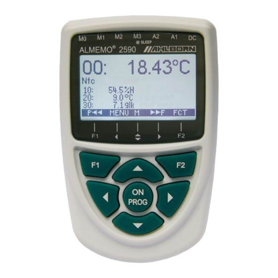
- Page 1 ____________________________ Operating instructions Universal measuring instruments and data loggers ® ALMEMO 2590-2/-3S/-4S V1.3 03.07.2007 www.ahlborn.com...
-
Page 2: Operating Controls
1. Operating controls 1. OPERATING CONTROLS (1) Measuring inputs M0 to M3 depending on type) M0 ... M3 Suitable for all ALMEMO ® sensors M10 ... M34 up to 16 additional channels Output sockets A1, A2 A1 V24 interface (ZA 1909-DK5) Optic fiber (ZA 1909-DKL) USB (ZA 19019-DKU) Ethernet (ZA 1945-DK) -
Page 3: Table Of Contents
Contents 2. CONTENTS 1. OPERATING CONTROLS ................. 2 3. GENERAL ....................6 3.1 Warranty ....................6 3.2 Scope of delivery ................7 3.3 Handling batteries / rechargeable batteries correctly ..... 7 3.4 Special notes on use ................7 4. INTRODUCTION ..................8 4.1 Functions..................... - Page 4 2. Contents 10.2.5 Atmospheric pressure compensation ........26 10.2.6 Cold junction compensation ........... 26 10.3 Differential measurement .............. 27 10.4 Menu Measuring points list ............27 10.5 User measuring menu U1 data logger .......... 28 10.6 User menus ..................29 10.6.1 Functions ................
- Page 5 Contents 12.8 Changing the units................49 12.9 Selecting the measuring range............50 12.10 Function channels ................ 53 12.11 Special meas. ranges ,Linearization ,Multi-point calibration ..54 12.12 Special functions................55 12.12.1 Print cycle factor..............55 12.12.2 Actions in the event of a limit value being exceeded..... 55 12.12.3 Analog start and analog end ..........
-
Page 6: General
3. General 3. GENERAL Congratulations on your purchase of this new and innovative ALMEMO ® data logger. Thanks to the patented ALMEMO ® connector the device configures it- self automatically and thanks to the menus and context-sensitive help windows its operation should be fairly straightforward. The device can, however, be used with such a wide range of sensors and peripherals and offers many differ- ent special functions. -
Page 7: Scope Of Delivery
Scope of delivery 3.2 Scope of delivery When you unpack the device check carefully for any signs of transport damage and ensure that delivery is complete. ® Measuring instrument ALMEMO 2590 with 3 AA alkaline batteries These operating instructions ALMEMO ®... -
Page 8: Introduction
4. INTRODUCTION ® The ALMEMO 2590 series is a new member in our family of unique measur- ® ing devices - all equipped with Ahlborn's patented ALMEMO connector sys- ® tem. The intelligent ALMEMO connector offers decisive advantages when connecting sensors and peripherals because all parameters are stored in an EEPROM located on the connector itself;... - Page 9 Functions Measuring ranges Appropriate measuring ranges are available for all sensors with a non-linear characteristic, e.g. 10 thermocouple types, NTC and PT100 probes, infrared sensors, and flow transducers (rotating vanes, thermoanemometers, Pitot tubes). For humidity sensors additional function channels are available for cal- culating humidity variables such as dew point, mixture ratio, vapor pressure, and enthalpy.
-
Page 10: Measuring Operations
4. Introduction mum). In the event of one of these limit values being exceeded an alarm signal is output and relay output modules actuate the associated alarm contacts; these can be allocated individually to specific limit values. Hysteresis is set by default to 10 digits but this can be adjusted to any number between 0 and 99. -
Page 11: Process Control
Functions Maximum and minimum values For each measuring operation the maximum value and minimum value are ac- quired and saved to memory. These values can then be displayed, printed out, or deleted from memory. Average value Manual averaging is available per channel over a certain period or cycle or over a series of individual measuring operations. - Page 12 4. Introduction Measured value memory On data logger 2590-3S or 2590-4S all measured values can be saved to an EEPROM either manually or automatically per cycle. Standard memory capaci- ty is 64 KB - sufficient for up to 12,000 measured values. The memory can be organized and configured in linear or ring form.
-
Page 13: Initial Commissioning
Initial commissioning 5. INITIAL COMMISSIONING Sensor connection Connect the sensor to any socket M0 to M3 (1); see Ch 7. via batteries or mains adapter to DC (3) ; see 6.1, 6.2 Power supply To switch ON press the (6) ; see 6.5 ON / PROG key Automatic display of last measuring menu see Ch 10. -
Page 14: Power Supply
6. Power supply 6. POWER SUPPLY Power can be supplied to the measuring instrument in any of the following ways : 3 AA alkaline batteries (included in delivery) Mains adapter 12V, 0.2A with ALMEMO connector ZA 1312-NA1 ® Electrically isolated power supply cable (10 to 30 VDC, 0.25 A) ZA 2690-UK Our product spectrum includes all the appropriate accessories. -
Page 15: Switching On / Off, Reinitialization
Switching ON / OFF, reinitialization 6.5 Switching ON / OFF, reinitialization To switch ON press key(s) : (6) located in the middle of the cursor PROGr block. The measuring menu most recently selected always appears first in the display. To switch OFF press and hold down the same key(s) . -
Page 16: Measuring Inputs And Additional Channels
7. Connecting the sensors / transducers tended disconnection if the cable is accidentally pulled. To withdraw the con- nector, both these levers must be pressed in at the sides. ® Splash-proof variants of devices in the ALMEMO 2590 series are also avail- able as options. -
Page 17: Potential Separation
Measuring inputs and additional channels 2590-2 2590-3 2590-4 sensor channels sensor channels sensor channels Device Device Device internal internal internal channels channels channels Average 4. chan. 3. chan. 2. chan. Difference 1. chan. M01-M00 M0 M1 M2 M0 M1 M2 M3 M0 M1 M2 M3 M4 7.3 Potential separation When organizing a properly functioning measuring setup it is very important to... -
Page 18: Display And Keypad
8. Display and keypad 8. DISPLAY AND KEYPAD 8.1 Display and menu selection The display (5) incorporated in the ALMEMO 2590 series consists of a dot ma- trix LCD display with 128x64 pixels, or 8 rows of 8 pixels each. Menu selection (see 9) provides the following : 3 measuring menus for acquiring measured values, Additional function menus (see 11), also accessible... -
Page 19: Function Keys
Measured value display and status symbols flashes / flashes Sensor breakage / sensor voltage Lo : Display ´-.-.-´ ´µµµµµµµµµ¶ Battery voltage <3.8 V, remaining capacity <10% flashes The data logger menus (see below) will also show in the menu's top status row the following symbols for checking the device status : Continuous measuring point scan ll or ©... -
Page 20: Function Selection
8. Display and keypad 8.4 Function selection Each menu comprises a number of functions; 25.45 these may have to be activated or programmed during operation. L840 flow º Temp. comp. 45.7 °C Atm. pressure 1027 mbar 03: 21.67 Pa dyn pressure ZERO In conjunction with certain functions a context- Sen sor adj ustment to :... - Page 21 Data input To cancel programming : <ESC> When entering alphanumeric characters select the group : upper case characters by pressing key(s) : <ABC> upper case characters by pressing key(s) : < abc > numbers only by pressing key(s) : < 123 > arithmetic signs by pressing key(s) : <...
-
Page 22: Menu Selection
UBat: 4.1 V Us: 9.1 V select any sensor by pressing key(s) ▲ ▼ www.ahlborn.com and identify it on the basis of its order number (if available). To determine the power supply re- Mªª MENU quirements both the battery voltage and the sen- sor voltage can be called up. -
Page 23: Selecting A Measuring Point
Menu Sensor display 10.1.1 Selecting a measuring point By pressing key you can select one after the other all active measuring points and have the current measured value displayed for each. By pressing you can move back to the previous channel. When a particular measuring ... -
Page 24: Sensor Adjustment For Dynamic Pressure Probes
10. Measuring menus 10.2.2 Sensor adjustment for dynamic pressure probes Dynamic pressure probes FDA602Sx must 0.45 undergo zero-point adjustment before each measuring operation by withdrawing the hoses. L840 flow º The zero-point error is always written to the cal- Temp comp 25.0 °C Atm pressure 1013 mbar... -
Page 25: Temperature Compensation
Measured value correction and compensation 3. Setting up a means of calibration for the slope. To select the measured value function press key(s) PROG Measured value shows e.g. 04.45 To initiate gain adjustment press key(s) <ADJ> Context-sensitive help window Sensor ad justment to with setpoint appears. -
Page 26: Atmospheric Pressure Compensation
10. Measuring menus 10.2.5 Atmospheric pressure compensation Measured variables dependent on the ambient atmospheric pressure (see Section 12.9 Measuring range list ´with PC´) may, in the event of large devia- tions from normal pressure (1013 mbar), involve certain measuring errors. e.g. -
Page 27: Differential Measurement
Differential measurement 10.3 Differential measurement If two sensors with the same units and same decimal point position are con- nected at measuring points M0 and M1, the difference M1 - M0 appears auto- matically below device-internal measuring point M2/M3/M4 (see 7.2). If the dif- ferential channel is not required, it must be explicitly deleted;... -
Page 28: User Measuring Menu U1 Data Logger
10. Measuring menus 10.5 User measuring menu U1 data logger User menu U1 can be freely configured by the C © REC COM l© ©l R01 * ´´´´´´µµµµ¶ user using the AMR-Control software (see 10.6). 27.6 °C A data logger menu is provided as standard. This menu can be used either on its own or just NiCr Temperature... -
Page 29: User Menus
User menus 10.6 User menus Despite these flexible combinations of measuring menus and function menus (see 11) there are still certain applications where an individual collection of functions would be desirable. This is the purpose of user menu U1 Data logger which can be also be assembled and configured completely freely using the AMR-Control software. -
Page 30: Menu Configuration
10. Measuring menus Empty line o 30 ______________________ Line o 31 Smoothing (see 11.2.1) o 32 Smoothing Memory capacity free (see 11.5.7) o 33 Memory free 502.1 KB CMEM PMEM Device designation (see.13.1) o 36 Company name - A Specimen Text 1: o 37 1: Designation line... -
Page 31: Function Menus
Function menus 11. FUNCTION MENUS Function menus max, min, ind. val memory © To manage individual tasks each measuring Averaging menu can be assigned a function menu from Two-point adjustment the adjacent list. For each measuring operation Scaling you can at any time toggle between measuring Data logger function s menu and function menu. -
Page 32: Averaging
11. Function menus 11.2 Averaging The average value for a measured value is needed for various applications e.g. smoothing a widely fluctuating measured value (wind, pressure etc.). Average flow velocity in a ventilation channel Hourly or daily average values for weather data (temperature, wind, etc.) Also for consumption values (electric current, water, gas, etc.) The average value M for a measured variable is obtained ∑... -
Page 33: Averaging Over Individual Manual Meas Operations
Averaging because this would at many measuring points Meas rate : 10 mops Cont : - reduce the measuring rate too strongly : Time constant (s) = smoothing / measuring rate · 2 How the averaging menus function : The following averaging menus use some of the standard functions such as averaging mode, cycle, measuring rate - appropriately repro- grammed. -
Page 34: Averaging Over The Cycle
11. Function menus Measuring rate m ∑ /N M= Start Stop To clear the average value and measuring duration automatically on Start (see 13.8) or having selected the average value by pressing : <CLR> The measuring duration can be read out : meas duration : 00:01:23.40 U To set memory activation, output format : <MON/MOFF>... -
Page 35: Averaging Over Measuring Points
Averaging 11.2.5 Averaging over measuring points The average value can also be determined over a number of associated measuring points. In menu 21.45 °C you can average value over measuring points set the start channel (Bk2) with the measuring point NTC Temperature in the 1st row and having selected the function to channel :... -
Page 36: Array Measuring Option Vn
11. Function menus 11.2.7 Array measuring Option VN Average velocity in a flow channel is calculated AVERAGING as per VDI 2080, namely by performing measur- Sliding average, smoothing ing operations at particular array points in a over measuring operations over time cross-section vertical to the pipe axis (see Man- over cycle ual 3.5.5). -
Page 37: Two-Point Adjustment With Setpoint Entry
Two-point adjustment with setpoint entry 11.3 Two-point adjustment with setpoint entry For universal error correction at any 2 points the function menu two-point adjustment TWO-POINT ADJUSTMENT provided. If the actual values at 2 points are 1.67 °C Temperature Actual val 1: ----- 2: ----- known , these can be written with the appropri- Setpoint 1: 0.00 2:... -
Page 38: Data Logger Functions
11. Function menus Scaling by means of a two-point adjustment Sensors which are adjusted via the factor, e.g. force transducers and displace- ment transducers, can also be adjusted online, as described previously in 11.3. Simulate, select, and enter 1st setpoint 1 : setpoint 1: -100.0 Adjust in setpoint 1 by pressing :... -
Page 39: Memory Connector With Multimedia Card
Data logger functions 11.5.2 Memory connector with multimedia card On devices without internal memory or if memory capacity proves insufficient or if the data needs to be evaluated elsewhere, you can, as additional external memory, use a memory connector (ZA 1904-MMC) with a conventional multi- media flash memory card, available from our range of accessories. -
Page 40: Once-Only Output / Saving Of All Measuring Points
11. Function menus 11.5.4 Once-only output / saving of all measuring points Once-only manual measuring point scans for acquiring the current measured values from all active measuring points (see Manual 6.5.1.1) can be initiated by pressing <MANU> . The output format can be set in the function Cycle timer (see 11.5.5, 11.5.8.3). -
Page 41: Numbering Of Measuring Operations
Data logger functions 11.5.6 Numbering of measuring operations To identify measuring operations or series of measuring operations these can be individually numbered before starting. This number is output or saved when the next measuring point scan starts. In this way individual measuring opera- tions can be assigned to certain types of measurement or certain measuring points (see Manual 6.7). -
Page 42: Scanning Configuration
11. Function menus 11.5.8 Scanning configuration Cycle : 00:01:00.00 In the following menu, reached by pressing Memory : Ø Mode: normal Output format : Columns <►F>, the general conditions for measuring Meas rate : 010 Cont : Ø point scans can be set in even greater detail. Memory : output Meas chan. - Page 43 Data logger functions With the selection of the Sleep mode after confirmation of a query display all necessary parameters are possibly configured! For data recording in sleep mode please perform the following steps : 1. Enter a cycle lasting at least 2 minutes Cycle : 00:05:00 S 2.
-
Page 44: Output Format
11. Function menus 11.5.8.3 Output format The output format (see Manual 6.6.1) defines the print layout for measuring point scans and for output of the memory. This output format can be pro- grammed in the function . There is the default format ´List´ in Output form which all measured values are listed one below the other;... -
Page 45: Memory Time
Data logger functions 11.5.8.5 Memory time An important parameter for data recording is the available memory time. This depends on the free memory capacity available, the measuring rate set, the scanning mode, and the number of active measuring channels. All these vari- ables are clearly shown via the menu described. -
Page 46: Sensor Programming
11. Function menus These values can be cleared after selecting the function by pressing : <OFF> If the start time for a measuring operation has been programmed, the following symbol appears in the status bar : ´l©´ If the end time or the measuring duration for a measuring operation has been programmed, the following symbol appears in the status bar : ´©l´... -
Page 47: Measuring Point Designation
Measuring point designation 12.2 Measuring point designation Each measuring point can be assigned a 10-character alphanumerical desig- nation denoting as clearly as possible the type of sensor, measuring location, and / or purpose. This designation is included in all standard measured value displays. -
Page 48: Limit Values
12. Sensor programming Locking level Locked functions None Measuring range + element flags + output mode + units + zero-point correction + gain correction + base value + factor + exponent + analog output, start and end + zero-point adjustment, temporary + limit values, maximum and minimum Locking level : Function Locking mode :... -
Page 49: Correction Values
Scaling, Decimal point setting The FACTOR can be programmed within the *SENSOR PROGRAMMING 2 * range -2.0000 to +2.0000. For factors below 0.2 Connector : 0 Channel : 5 Base value : ------ °C or above 2.0 an appropriate decimal point set- 5 Factor, Exp : ------E0 ting should be used by entering the EXPO-... -
Page 50: Selecting The Measuring Range
12. Sensor programming If you enter °F as units the temperature value will be converted auto- matically from degrees Celsius to degrees Fahrenheit. If you enter !C cold junction compensation will be disabled. If you enter the appropri- ate two characters the following units are generated automatically; for m¡... - Page 51 Selecting the measuring range ZA 9000-FS 0.0...+1760.0 °C Pt13 PtRh13-Pt (R) ITS90 ZA 9000-FS +400.0...+1800.0 °C EL18 PtRh30-PtRh6 (B) ITS90 ZA 9000-FS -270.0... +60.0 °C AuFe Au-FeCr ZA 9000-SSC 0.0...+2320.0 °C WR26 W5Re-W26Re (C) NTC type N ZA 9000-FS -30.00...+125.00 °C ZA 9040-SS3 0.000...+45.000...
- Page 52 12. Sensor programming Function parameters : FH A646 0.0 ... 500.0 g/kg H AH * Mixture ratio, with PC FH A646 -25.0... 100.0 °C H DT * Dew-point temperature FH A646 0.0...1050.0 mbar H VP * Partial vapor pressure FH A646 0.0 ...
-
Page 53: Function Channels
Function channels 12.10 Function channels At the end of the table of measuring ranges and units (see above) under the sub-heading function channels there is a group of ranges that can be used to represent function parameters for measured value processing or for calculated results obtained by linking certain measured values on measuring channels (see Manual 6.3.4). -
Page 54: Special Meas. Ranges ,Linearization ,Multi-Point Calibration
12. Sensor programming Advantage of device-internal channels If several sensors are being used for the same application, they do not have to be reprogrammed and can be freely exchanged without losing their function channel assignment. However, if the whole application operates with just one sensor, then programming on the sensor itself makes more sense. -
Page 55: Special Functions
Special functions 12.12 Special functions On the 2590 measuring instrument, in the 2 SPECIAL FUNCTIONS menus, all sensor parame- SPECIAL FUNCTIONS Connector : 0 Channel : ters can be accessed; these may be needed Print cycle factor : 7 Action, max : Start R21 only occasionally in routine operation but may 7 Action, min :... -
Page 56: Analog Start And Analog End
12. Sensor programming To activate relay "xx" in the event of overshooting limit value maximum : 7 Action, maximum : ----- To activate relay "xy" in the event of 7 Action, minimum : ----- undershooting limit value minimum : <CLR> To clear relay assignment press Socket A2 ZA8006RTA3... -
Page 57: Minimum Sensor Supply Voltage
Special functions 12.12.4 Minimum sensor supply voltage As with all ALMEMO devices the sensor sup- ® * SPECIAL FUNCTIONS 2 * ply voltage on the 2590 is monitored. The sen- Sensor voltage, min : 12.0 V sor supply voltage is displayed in the INFO 1 Output function : MEAS (see 9). -
Page 58: Reference Channel 1
12. Sensor programming 12.12.6 Reference channel 1 The calculating functions of the function channels usually refer to one (or two) particular measuring channel(s) (see 12.10, Manual 6.3.4). When program- ming a function channel the reference channel M is is provided automatically by the 1st channel of the associated sensor connector M . -
Page 59: Device Configuration
Time 12:34:56 Date 01.01.04 day, date (see 11.5.3), language, and illumina- Device designation tion. The device designation can be used as Ahlborn, Holzkirchen Language : German print header in a log printout or to facilitate as- Illumination : Ø Duration : 20s signment in a a network. -
Page 60: Interface, Device Address, And Networking
13. Device configuration 13.4 Interface, device address, and networking Via the serial interface you can output cyclic Device address : data logs, all function values from the measur- Baud rate 9600 baud ing menus, and all the programming details for Atm pressure 1013 mbar Temp comp... -
Page 61: Hysteresis
Hysteresis 13.7 Hysteresis The hysteresis for an alarm triggered in the event of a limit value being exceed- ed can be set generally for all sensors from 0 to 99 digits (default 10 digits) in the Hysteresis function (see 12.5 and Manual 6.2.7). Hysteresis : To modify hysteresis (0 ... -
Page 62: Relay-Trigger Modules
14. Output modules 14.2 Relay-trigger modules While V5 modules permit only one module (relay, trigger input, or analog out- put) with just one function variant for all elements, the ALMEMO 2590 can ® have several V6 output modules connected and all elements can be individual- ly configured in all their function variants. -
Page 63: Analog Outputs
Relay-trigger modules Status : active open Activation mode and relay contact status : Relay variant 8 ´Driven externally´ permits manual activation via the keypad or via the interface; (see Manual 6.10.10). Relay variant 8: 8: Driven externally <ON> <OFF> For manual activation of relays press : Trigger inputs For the purpose of controlling the measuring se- OUTPUT MODULES... -
Page 64: Scaling The Analog Output
14. Output modules This gives, depending on the analog output, the following output signals : Voltage output -1.2 ... +2.00 V 0.1 mV / digit Voltage output -6.0 ... +10.0 V 0.5 mV / digit Current output 0.0 ... 20.0 mA 1 µA / digit In variant 2 ´Assigned internally´, after selecting the Mxx function, it is possible to program the measuring point to be output :... -
Page 65: Trouble-Shooting
Trouble-shooting 15. TROUBLE-SHOOTING The ALMEMO 2590 measuring instrument can be configured and pro- ® grammed in many versatile ways. It is suitable for connecting a wide variety of different sensors, additional measuring instruments, alarm signaling devices, and peripheral equipment. Given these numerous possibilities the device may in certain circumstances not behave quite as expected. -
Page 66: Electromagnetic Compatibility (Emc)
15. Trouble-shooting Test the receive line by pressing <MANU> and check in the display. Error: Data transmission in the network does not function. Remedy: Check to ensure that all devices are set to different addresses. Ad- dress all devices individually via the terminal using command ´Gxy´. Addressed device is OK if at least ´y CR LF´... -
Page 67: Appendix
Appendix 17. APPENDIX 17.1 Technical data (see Manual 2.3) Measuring inputs : 2590-2/3/4 2/3/4 ALMEMO ® sockets for ALMEMO ® connectors Measuring channels : 2/3/4 primary channels, electrically isolated, 3 additional channels per input for double sensors and function channels A/D converter : Delta-sigma, 16-bit, 2.5/10mops, Reinforcement 1.38 Sensor power supply :... -
Page 68: Product Overview
7 keys, LCD graphics display, real-time clock MA 2590-2 Universal measuring instrument and data logger ALMEMO 2590-3S Like the ALMEMO 2590-2 but 3 inputs and 59-KB EEPROM memory MA 2590-3S Universal measuring instrument with data logger function ALMEMO 2590-4S Like the ALMEMO 2590-3S but 4 inputs... -
Page 69: Index
Index 17.3 Index Accessories 17.2 Action, maximum and Action, minimum 12.12.2 Actions in the event of a limit value being exceeded 12.12.2 activation mode 14.2 Active 11.5.8.5 additional channels alarm relay cable 12.12.2 AMR-Control 10.6.2 12, 30 AMR-Control software 10.5 Analog outputs 14.3 Analog start and analog end... - Page 70 17. Appendix Current output 14.3 Cyclic output 11.5.5 Data buffering Data cables 14.1 Data format 13.5 Data input data logger 10.5 Data logger functions 11.5 Date 11.5.3 Decimal point setting 12.6 depth 11.2.6 Designation 12.2 device address 13.4 Device configuration Device designation 13.1 Device-internal channels...
- Page 71 Index Inverted relay control 14.2 keypad Language 13.2 level of smoothing 11.2.1 Limit values 12.5 Linearization 12.11 Locking the sensor programming 12.4 Mains operation manual measuring point scan 11.5.4 Maximum, minimum, individual values memory 11.1 Meas chan. 11.5.8.5 Measured value correction 10.2 Measured value display and status symbols measuring depths...
- Page 72 17. Appendix Output modules Potential separation Power supply 17.1 14, 67 Print cycle factor 12.12.1 Process control 4.1.3 Product overview 17.2 Programmed analog value output 14.3 programming menus Reference channel 1 12.12.6 Reference channel 2 12.12.7 refrigerants 12.9 reinitialization relay adapter 12.12.2 Relay assignment 12.12.2...
- Page 73 Index Start time 11.5.9 Starting and stopping measuring operations 11.5.9 Suitable conditions 17.1 supply voltage monitoring Surface 11.2.6 Switch memory activation 11.5.5 switch OFF Switching ON / OFF Technical data 17.1 temperature compensation 13.6 Temperature compensation 10.2.4 The measuring duration can be read out 11.2.3 Time constant 11.2.1...
-
Page 74: Your Contact
17. Appendix 17.4 Your contact ALMEMO ® 2590... - Page 75 Your contact ALMEMO ® 2590...
- Page 76 17. Appendix ALMEMO ® 2590...
Need help?
Do you have a question about the ALMEMO 2590-2 and is the answer not in the manual?
Questions and answers