
Related Manuals for Ahlborn ALMEMO 2470-1S


Summary of Contents for Ahlborn ALMEMO 2470-1S
- Page 1 ____________________________ Operating instruction English Universal measuring instruments with ® color display ALMEMO 2470-1S,-1SRH-2,-2S V2.0 30.08.2012 www.ahlborn.com...
-
Page 2: Operating Controls
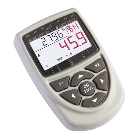
1. 1 Operating controls 1. 1 OPERATING CONTROLS * only 2470-2, -2S (1) Meas. inputs M0 und M1* M0 ... M1* for all ALMEMO sensors M10..30 3 additional channels M4* Function channel, differential M11*..M34* 6 additional channels (2) Outputs A1*, A2* A1* USB interface (ZA 19019-DKU) RS 232 (ZA 1909-DK5) Ethernet (ZA 1945-DK) -
Page 3: Table Of Contents
Contents 2. CONTENTS 1. 1 OPERATING CONTROLS ..............2 3. GENERAL....................5 3.1 Warranty....................5 3.2 Standard delivery................6 3.3 Waste disposal..................6 4. SAFETY INSTRUCTIONS................7 4.1 4.1 Special notes on use..............8 4.2 Handling batteries / rechargeable batteries correctly......8 5. INTRODUCTION..................9 5.1 Functions..................... 9 5.1.1 Sensor programming..............10 5.1.2 Measuring operation..............11 5.1.3 Process control ................12... - Page 4 2. Contents 10.7 Pressure compensation..............29 10.8 Differential measurement...............29 11. FUNCTIONS.....................30 11.1 Sensor functions................31 11.1.1 Base value and factor...............31 11.1.2 Smoothing................31 11.1.3 Limit values................31 11.2 Data logger functions..............32 11.2.1 Internal data memory..............32 11.2.2 External memory connector fitted with a memory card.....33 11.2.3 Memory capacity display............33 11.2.4 Cycle..................34 11.2.5 Date and time-of-day..............35...
-
Page 5: General
General 3. GENERAL Congratulations on your purchase of this new and innovative ALMEMO ® meas- uring instrument. Thanks to the patented ALMEMO ® plug the device configures itself automatically; its operation should be fairly straightforward. The new color display helps show with particular clarity various important operating states, e.g. -
Page 6: Standard Delivery
3. General 3.2 Standard delivery When you unpack the device please check carefully for any signs of transport damage and ensure that delivery is complete: Measuring instrument ALMEMO ® 2470-1S with 3 AA batteries or Measuring instrument ALMEMO 2470-1SRH with integrated ®... -
Page 7: Safety Instructions
Safety instructions 4. SAFETY INSTRUCTIONS DANGER Danger to life and limb, risk of damage to equipment Before starting to operate the device, please read the in- structions carefully. Please ensure that you comply with all general safety ad- vice and the special safety instructions included in other chapters! Such risks may occur in the following circumstances: Failure to heed the operating instructions and all the... -
Page 8: Special Notes On Use
4. Safety instructions DANGER Warning - explosive atmospheres or substances In the vicinity of various fuels or chemicals there is a risk of ex- plosion Do not use the device in the vicinity of blasting work or filling stations 4.1 4.1 Special notes on use If the device is brought into the work-room from a cold environment •... -
Page 9: Introduction
Introduction 5. INTRODUCTION The ALMEMO ® 2470 is a new member in our family of unique measuring devices - all equipped with Ahlborn's patented ALMEMO ® plug system. The in- telligent ALMEMO ® plug offers decisive advantages when connecting sensors and peripherals because all parameters are stored in an EEPROM located in the plug itself;... -
Page 10: Sensor Programming
5. Introduction 5.1.1 Sensor programming The measuring channels are programmed, completely and automatically, via the ALMEMO plugs. However, this programming can be supplemented or ® modified via the keypad or via the interface as and when required for measur- ing purposes. Measuring ranges Appropriate measuring ranges are available for all sensors with a non-linear characteristic, e.g. -
Page 11: Measuring Operation
Functions Limit values and alarm Per measuring channel two limit values can be set (1 maximum and 1 minim- um). In the event of one of these limit values being exceeded the beeper sounds and the display backlighting changes from white to red. This alarm status can be cancelled at the touch of a button. -
Page 12: Process Control
5. Introduction pressure sensors, and O2 sensors; on this device this is performed automatic- ally by means of an integrated atmospheric pressure sensor. Measured value smoothing Measured values of an unstable, fluctuating nature can be smoothed by taking a sliding average over a number of values programmable from 2 to 99. Maximum and minimum values For each measuring operation the maximum value and minimum value are ac- quired and saved to memory. - Page 13 Functions Measuring rate All measuring points are scanned at the measuring rate (2.5 or 10 mops). The output of all measured values via the interface can also be performed at the measuring rate; this will accelerate recording. Measured value memory (2470-1S/2S only) On data logger 2470-1S or 2470-2S all measured values can be saved to its internal EEPROM either manually or automatically per cycle.
-
Page 14: Putting Into Service
6. Putting into service 6. PUTTING INTO SERVICE 1. Connect the sensor to socket M0 (1). see Chapter 8 2. Power supply is via batteries, rechargeable battery pack, or mains adapter. see 7.1, 7.3 3. Switch on by pressing (6). see 7.6 4. -
Page 15: Rechargeable Battery Operation And Supply Voltage Monitoring
Power supply Power supply cable, electrically isolated (10 to 30 VDC, 0.25 A) ZA 2690-UK 12 VDC via clamp connector at DC socket ZA 1000-FSV Our product spectrum includes all the appropriate accessories. 7.1 Rechargeable battery operation and supply voltage monitoring Power is supplied to measuring instruments 2470-2/2S as standard by 3 AA re- chargeable NiMH batteries. -
Page 16: External Dc Voltage Supply
7. Power supply bar indicates the approximate charge status. While the 3 green sections flash left to right, the rechargeable batteries are being charged. As soon as all 3 sections remain green, the rechargeable batteries are fully charged; however, the mains adapter can be left connected to the device. If standard non-re- chargeable batteries are being used, the battery symbol will, as soon as the mains adapter is connected, flash briefly in red. -
Page 17: Data Buffering
Data buffering 7.7 Data buffering The sensor's programming is stored in the EEPROM on the sensor plug; the device's calibration and programmed parameters are stored in the EEPROM on the device itself; both are fail-safe. Date and time-of-day settings are re- tained intact if the device is just switched off but will be lost as and when the batteries are replaced. -
Page 18: Potential Separation
8. Connecting sensors / transducers M24, M34. On the 2470-1SRH with its integrated sensors these are used for the channels temperature, humidity, dew point, and atmospheric pressure. On the other variants M4 is programmed by default as differential channel M1 –... -
Page 19: Display And Keypad
Potential separation taic relays and a potential difference of maximum 50 VDC or 60 VAC is per - missible between them. However, sensors combined within one plug and sensors with their own power supply are electrically interconnected and must therefore be operated in isolation. The voltage at the measuring inputs them- selves (between B, C, D and A or - ) must not exceed 5 volts. - Page 20 9. Display and keypad Configuration - device address Configuration - locking AOFF Configuration - automatic device OFF dOFF Configuration - display OFF Special operating states and faults Segment test for display This is performed automatically each time the device is switched on. Supply voltage Display after segment test Below 3.3 V :...
- Page 21 Display Displays in main field Non-connected sensors, ----- Deactivated measuring points Checksum error during CALEr device calibration Function locked noOFF Switching OFF while charging not possible Measuring range / function not possible Er.MEM Memory configuration altered NiCr Sensor breakage Abbreviation flashes Measuring range undershot, (Cold junction) CJ or CJ breakage...
-
Page 22: Keypad
9. Display and keypad 9.2 Keypad To operate the device a keypad with 7 keys is provided. Basic functions To switch the device ON (s. 7.6) To switch the device OFF press and hold down M ▲ M ▼ To select measuring points (s. 10.2.1) To display maximum value (s. -
Page 23: Measuring Operations
Measuring operations 10. MEASURING OPERATIONS With the ALMEMO ® 2470 all available measuring channels are by default scanned continuously; this permits continuous differential measurements and ensures continuous temperature compensation for dynamic pressure probes or chemical probes. (see Manual, 6.5.1.3) Up to 12 measuring channels can be displayed. -
Page 24: Measuring Ranges
10. Measuring operations 10.2.2 Measuring ranges Whenever there is a channel switchover or sensor breakage the measuring range abbreviation appears in the display. The following table lists all the measuring ranges possible. Sensors / transducers Sensor / plug Measuring range Units Abbrevi- ation... - Page 25 Measured value Sensors / transducers Sensor / plug Measuring range Units Abbrevi- ation L840 Dyn. press., 40 m/s, with TC and PC FD A612-M1 0.50 to 40.00 L890 Dyn. press., 90 m/s, with TC and PC FD A612-M6 1.00 to 90.00 % rH Rel.
-
Page 26: Double Display
10. Measuring operations 10.2.3 Double display On all double-function sensors incorporating a temperature sensor on the first channel the temperature value can be displayed at the same time in the function field. Set device locking to 0. (see 13.2) Select 2nd channel. To activate temperature display, press and hold down M▲... -
Page 27: Relative Measuring
Individual value memory The value most recently saved then appears in the function field preceded by the symbol ´M´. M ▲ To return to the channel display press To display all memory data press and hold down The function field displays the last memory location;... -
Page 28: Sensor Adjustment
10. Measuring operations Setting to zero automatically deletes the maximum and minimum val- ues for this channel. The MAX, MIN, and MEM functions are thus also available for relative measuring. 10.6 Sensor adjustment Many types of sensor need to be adjusted either once or at regular intervals to compensate for various instabilities. -
Page 29: Pressure Compensation
Sensor adjustment 2. Gain adjustment For the purposes of gain adjustment the gain calibration resource must first be set up (as per the Table). Gain adjustment is started, similarly, by pressing key PROG and performed in exactly the same way as zero-point adjustment. -
Page 30: Functions
10. Measuring operations ference M1 - M0 appears automatically below the measuring point M4. The sensors are electrically isolated by means of photovoltaic relays. If the differen- tial channel is not required, it can be deleted via the interface. If. on the other hand, further differential channels are needed, these can be created also via the interface using the appropriate reference channels. -
Page 31: Sensor Functions
Sensor functions 11.1 Sensor functions On a number of sensors, e.g. moisture content sensors, it may be necessary before measuring to program correction values, i.e. base value or factor; for measured values of an unstable, fluctuating nature smoothing would be advis- able. -
Page 32: Data Logger Functions
11. Functions If any measured value overshoots or under- shoots its associated limit values, the associ- ated channel is selected automatically, the measured value is displayed on an illuminated red background, and an acoustic alarm is out- put. Whether the limit value in question is an overshot MAX or undershot MIN is indicated by the direction of the flashing arrow ▲... -
Page 33: External Memory Connector Fitted With A Memory Card
Data logger functions ledged by pressing ´OK´, the question ´CMEM´ appears. If ´OK´ is now pressed the memory content will be cleared and the measuring operation starts. If ´ESC´ is pressed instead, the memory content is not cleared and measured value re- cording is continued - but incorrectly configured (units, measuring range). -
Page 34: Cycle
11. Functions As and when this memory becomes full, the ´FrEE´ display will show 0.00; no further meas- ured values will be saved. However, the in- ternal memory can be configured as ring memory. see Manual, 6.10.13.2 To completely delete the memory’s contents CMEM flashes PROG To confirm (OK) or to cancel (ESC) press... -
Page 35: Date And Time-Of-Day
Data logger functions Please note that alarm displays will increase current consumption and, depending on the operating period, shorten the battery’s useful life. To acknowledge - and thus terminate - alarm display when in sleep mode press the key. The acoustic alarm signal will end automatically after 10 seconds. -
Page 36: Outputs
11. Functions may be used “list”, “columns”, or “table”. It is possible to specify certain sec- tions of the memory for output - either by stipulating the start time and end time or by selecting the numbers defining the measuring operations in question. With external SD memory cards the device itself can usually only read out measured data contained in the file most recently used;... -
Page 37: Device Configuration
Device configuration 13. DEVICE CONFIGURATION A number of parameters that need to be modi- fied only very rarely can be specially pro- grammed in `Device configuration`. When switching ON press and hold down key . The function field should then show an ab- breviation for the parameter and the main field should show the value currently set. -
Page 38: Automatic Device Switch Off
13. Device configuration Locking code VC Functions ▲ ▼ Select measuring points, display measured value ● ● ● ● M , M M ▲ press and hold down Program double display ● ● ● ● UBat display ● ● ● ●... -
Page 39: Atmospheric Pressure
Atmospheric pressure 13.5 Atmospheric pressure To perform pressure compensation on various sensors (see 10.2.2, with PC) the current atmo- spheric pressure is required. (see 10.7) The atmospheric pressure can be pro- grammed explicitly in menu item ´P mb´. (see 9.3) If atmospheric pressure at a measuring point is used for compensation purposes a symbol ´P´... -
Page 40: Declaration Of Conformity
/ or print out a comprehensive "Function test" in the device list or terminal mode. 15. DECLARATION OF CONFORMITY Ahlborn Mess- und Regelungstechnik GmbH declares herewith that measuring instrument ALMEMO ®... - Page 41 Declaration of conformity Safety EN 61010-1: 2001 EMC: EN 61326: 2006 If a product is modified in any manner not agreed with us in advance, this de- claration becomes void. When using the sensor with an extension care must be taken to ensure that wiring is not laid alongside or close to high-voltage power cables and that it is if necessary properly shielded so as to prevent spurious interference being in- duced in the system.
-
Page 42: Annex
16. Annex 16. ANNEX 16.1 Technical data (see Manual. 2.3) Measuring inputs 2470-1S 1 ALMEMO socket M0 for ALMEMO sensors ® ® 4 measuring channels 2470-1SRH Same as above, with integrated temperature / humid- ity sensor and atmospheric pressure sensor 4 additional meas. -
Page 43: Product Overview
Technical data Suitable conditions Operating temperature -10 to +50 °C Storage temperature -20 to +60 °C Ambient relative humidity 10 to 90 % RH (non-condensing) 16.2 Product overview Universal measuring instrument ALMEMO ® 2470-1S Order no. 1 ALMEMO measuring input, 2-row color segment LCD, 7 keys, ®... -
Page 44: Index
16. Annex 16.3 Index Accessories 16.2 acoustic alarm 11.1.3 additional channels Ambient relative humidity 16.1 AMR-Control 5.1.3 Atmospheric pressure 13.5 Base value 11.1.1 batterie Battery operation battery symbol Battery voltage 10.1 CALEr cancel function cancel inputs change the arithmetic sign channel assignment charge status charges the rechargeable batteries... - Page 45 Index Device locking 13.2 device switch OFF 13.3 Device-internal channels differential channel Differential measurement 10.8 DIN top hat rail mounting 16.2 Display Display illumination 13.4 Double display 10.2.3 dynamic pressure probes 10.6 Dynamic pressure probes 10.7 EEPROM 11.2 electromagnetic compatibility Entering data Er.MEM 11.2.1...
- Page 46 16. Annex Main field mains adapter Mains adapter 16.2 manual measured value scans 11.2.6 maximum value 10.3 Measured value 10.2 Measured value recording 11.2.6 measured value to zero 10.5 Measuring inputs 2, 17 Measuring operations measuring range abbreviation 10.2.2 Measuring range overshot Memory capacity display 11.2.3 memory card...
- Page 47 Index Reading out the memory 11.2.7 rechargeable batterie Rechargeable battery reference channels reference value 10.5 reinitialization Relative measuring 10.5 relay trigger adapter 16.2 replace used batteries ring memory 11.2.3 Rubber guard 16.2 Safety instructions SD card 11.2.2 segment test 10.1 select a function Selecting a measuring point 10.2.1...
-
Page 48: Your Contact Partner
WIN-Control 5.1.3 Zero-point adjustment 10.6 16.4 Your contact partner Ahlborn Mess- und Regelungstechnik GmbH, Eichenfeldstraße 1-3, D-83607 Holzkirchen, Germany Tel. +49(0)8024/3007-0, Fax +49(0)8024/300710 Internet: http://www.ahlborn.com, e-mail: amr@ahlborn.com We take every possible care but the risk of inaccuracy can never be altogether excluded.
Need help?
Do you have a question about the ALMEMO 2470-1S and is the answer not in the manual?
Questions and answers