
Subscribe to Our Youtube Channel
Related Manuals for Ahlborn ALMEMO 710


Summary of Contents for Ahlborn ALMEMO 710
- Page 1 Operating instructions Data logger ALMEMO ® V1.6 13.07.2015...
-
Page 2: Operating Controls
1. Operating controls 1. OPERATING CONTROLS (1) Measuring sockets M0 to M9 (5) Status LEDs M0 ... M9 for all ALMEMO sensors START Meas. operation is running. M0.0...M9.9 for up to 100 meas. chan- Data is being saved. nels Data is being output. (2) Output sockets A1, A2, A3 ALARM Limit value infringement. -
Page 3: Table Of Contents
3.3 Waste disposal..................7 4. SAFETY INSTRUCTIONS................8 4.1 Special notes on use................9 4.2 How to deal with rechargeable batteries...........9 5. INTRODUCTION..................10 5.1 Functions of the ALMEMO 710............11 5.1.1 Sensor programming..............11 5.1.2 Measuring operation..............12 5.1.3 Process control................13 6. PUTTING INTO SERVICE................16 7. POWER SUPPLY..................17 7.1 7.1 Rechargeable battery operation and supply voltage monitoring... - Page 4 2. Table of contents 10.1.2 Scan cycle with output..............27 10.1.3 Output cycle................29 10.1.4 Memory, internal...............29 10.1.5 Memory connector with memory card........30 10.1.6 Numbering of measuring operations........31 10.2 Memory - comments text..............31 10.3 Scan mode..................31 10.4 Starting and stopping measuring operations.......33 10.4.1 Start date and time, Stop date and time........33 10.4.2 Fixed measuring period............34 10.5 Memory status, delete memory content........34...
-
Page 5: Table Of Contents
Table of contents 13.2.13 Quantities................53 13.2.14 Channel compensation............58 13.3 Display settings................58 13.4 Data logger settings................58 13.5 Output modules................58 13.5.1 Data cables................58 13.5.2 Relay trigger modules...............59 13.5.3 Analog output................60 13.6 Device settings................61 13.6.1 Communication................61 13.6.2 Macros..................62 13.6.3 Operating parameters..............63 13.6.4 Device compensation values............63 13.6.5 Calibration data................63 13.6.6 General device settings............63 13.7 Blocking function................64... -
Page 6: General
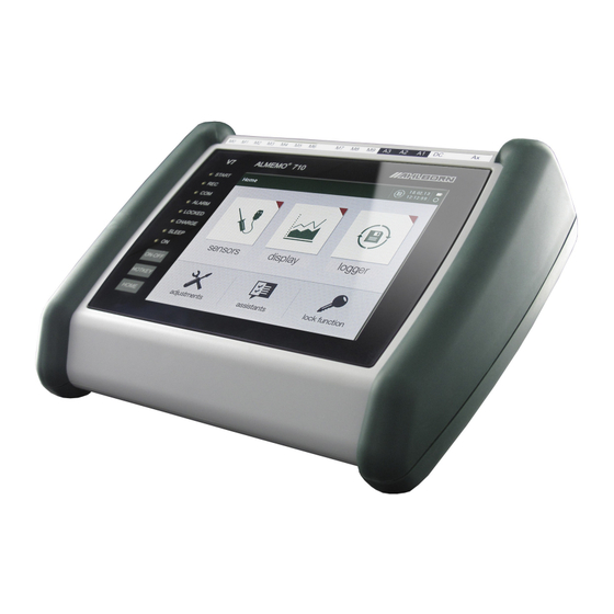
3. General 3. GENERAL Congratulations on your purchase of this latest V7-generation ALMEMO® data logger. Thanks to the patented ALMEMO ® plug the device configures itself au- tomatically and thanks to the self-explanatory touchscreen its operation should be fairly straightforward. The device can, however, be used with such a wide range of sensors and peripherals and offers many different special functions. -
Page 7: Standard Delivery
Standard delivery 3.2 Standard delivery When you unpack the device please check carefully for any signs of transport damage and ensure that delivery is complete. Measuring instrument ALMEMO ® • with 2 rechargeable battery packs and folding stand • Mains adapter •... -
Page 8: Safety Instructions
4. Safety instructions 4. SAFETY INSTRUCTIONS DANGER Danger to life and limb, risk of damage to equipment Before starting to operate the device, please read the in- structions carefully. Please ensure that you comply with all general safety ad- vice and the special safety instructions included in other chapters. -
Page 9: Special Notes On Use
Special notes on use 4.1 Special notes on use If the device is brought into the work-room from a cold environment • there is a risk that condensation might form on the electronics. In mea- suring operations involving thermocouples pronounced changes in temperature may cause substantial measuring errors. -
Page 10: Introduction
5. INTRODUCTION The V7 data logger ALMEMO ® 710 is a brand new member in our family of unique measuring instruments - all equipped with Ahlborn GmbH's patented ALMEMO ® plug system. The ALMEMO ® plug offers - and has offered for the last 20 years - decisive advantages when connecting sensors and peripherals because all param- eters are stored in an EEPROM located on the connector itself;... -
Page 11: Functions Of The Almemo 710
Functions of the ALMEMO 710 5.1 Functions of the ALMEMO 710 The ALMEMO ® 710 data logger has 10 electrically isolated measuring inputs - suitable for all ALMEMO ® sensors. Given the large portfolio of already existing standard sensors and now the new, innovative D7 sensors measuring possibili- ties are virtually limitless. -
Page 12: Measuring Operation
5. Introduction each measuring channel in such a way that both the display and the printout al- ways indicate the correct units, e.g. when a transmitter is connected. Conver- sion between °C (Centigrade) and °F (Fahrenheit) is performed automatically. Measured value designation To help identify sensors an alphanumeric designation is also provided (V5 - 10 characters, D7 - up to 20 characters). -
Page 13: Process Control
Functions of the ALMEMO 710 menus as measured value list, single display, bar chart, or line graph. Mea- sured values are acquired automatically with auto-zero and self-calibration; however, they can also be corrected and scaled as and whenever required. With most sensors a sensor breakage is detected automatically. - Page 14 5. Introduction Date and time-of-day Each measuring operation can be accurately logged using the real-time clock in terms either of date and time-of-day or purely by actual measuring duration. For the purposes of starting / stopping a measuring operation, the start / stop date and time-of-day can be programmed.
- Page 15 Functions of the ALMEMO 710 Up to 10 output relays or 4 analog outputs can be addressed individually via the touchscreen or via the interface with a relay trigger adapter . Via the trigger inputs it is also possible for external events to influence the measuring se- quence.
-
Page 16: Putting Into Service
6. Putting into service 6. PUTTING INTO SERVICE Sensor connection Connect sensors to sockets M0 to M9 (1). see 8 Power supply Via rechargeable battery or charge adapter connected at socket DC (3) see 7.1, 7.2 To switch ON Press and hold down touchkey (6) . -
Page 17: Power Supply
Power supply 7. POWER SUPPLY Power can be supplied to the measuring instrument in any of the following ways : Integrated lithium-ion battery pack, 4.2 V / 15.6 Ah as standard Mains adapter / charge adapter, 12 V, 2.5 A ZA 1312-NA9 Power supply cable, electrically isolated (10 to 30 VDC, 1 A) ZB 2690-UK2... -
Page 18: Sensor Supply
7. Power supply ever, the power supply has to be electrically isolated from the transducers or if a larger input voltage range (10 to 30 V) is required, then electrically isolated supply cable ZA 2690-UK2 (12V, 1A) must be used. It will then be possible to use the device in a 12-volt or 24-volt on-board supply system;... -
Page 19: Sensor Connection
Sensor connection 8. SENSOR CONNECTION Virtually any ALMEMO ® sensor can be connected at any of ALMEMO ® input sockets M0 to M9 (standard so-called V5 sensors and newer D6 and D7 digital sensors included). The ALMEMO ® Manual includes detailed descriptions of the comprehensive ALMEMO ®... -
Page 20: D7 Sensors
8. Sensor connection 8.3 D7 sensors ALMEMO ® D7 sensors are housed in a dark-red case; they too are completely autonomous measuring modules for digital and for analog sensors - but offer substantially enhanced properties. The conversion rate can be set from 1 mil- lisecond up to several minutes with a resolution up to 8 digits. -
Page 21: Potential Separation
Potential separation 8.5 Potential separation When organizing a properly functioning measuring setup it is very important to ensure that no equalizing current can flow between sensors, power supply, and peripherals. All measuring points must therefore either be insulated (e.g. by air spacing) or lie at the same potential - and any unequal potentials that do exist must be electrically isolated. -
Page 22: Display And Keypad
9. Display and keypad 9. DISPLAY AND KEYPAD The operator interface (7) on data logger ALMEMO ® 710 is a state-of-the-art capacitive touchscreen; the display comprises five 7" TFT LCDs (VGA resolu- tion 640 x 480 pixels); there are also 3 additional touchkeys (6). 9.1 Touchkeys The touchkeys (6) operate independently of the touchscreen. -
Page 23: Function Keys
Function keys 9.3 Function keys For the purpose of controlling measuring operations there are just a few super- ordinate keys located along the bottom edge of the screen. To start a cyclic measuring operation see 10.4 To stop a cyclic measuring operation Once-only manual output / saving of all measured values Call up settings for local menu key in the menu... -
Page 24: List Of Parameters
9. Display and keypad 9.6 List of parameters All measured values and parameters are shown in fields in various ways to- gether with additional symbols. Measured value Limit value overshoot in red Limit value undershoot in blue Measuring range overshot OVERRANGE flashes Measuring range undershot UNDERRANGE flashes Sensor breakage BREAK flashes Sensor voltage too low U-LOW flashes... - Page 25 Entering data Enter alphanumeric designations using the alphanumeric keypad. e.g. Measuring channel designation For upper-case letters 123/#*. For numbers and special symbols For letters only Save settings Some device settings can only be used on a temporary basis; others can be permanently saved. Other data that can be entered Selection box Quasi-analog values (display brightness)
-
Page 26: Data Logger
10. Data logger 10. DATA LOGGER Normally the function of this measuring instrument is, using suitable sensors, acquire specified measured values in a specified chronological quence and to save these to a specified storage medium. Since these sensors are nor- mally already fully programmed by the ALMEMO ®... -
Page 27: Conversion Rate
Measured value acquisition / output If the user touches on the button ´Save-to-memory cycle´ and then selects ´greater than 1s´ or ´less than 1s´ this is usually equivalent to choosing be- tween the output cycle and the scan cycle. Or, instead of the scan cycle, the user can enter the desired scans per second directly. - Page 28 10. Data logger dated since the last scan; i.e. in a short scan cycle only high-speed sensors will appear for most of the time, the slower ones being added at larger intervals. This method ensures that the measuring instrument can adapt to a wide variety of sensors - without duplicating a lot of unwanted data.
-
Page 29: Output Cycle
Measured value acquisition / output 10.1.3 Output cycle Measured values can be saved and / or output via the interface on a cyclic ba - sis using the ´Output cycle´ in the format h/m/s. If a channel is programmed to averaging mode CYCL, average, maximum, and minimum values are all deleted with each cycle. -
Page 30: Memory Connector With Memory Card
10. Data logger A user requesting memory content to be deleted is asked to con- firm; if confirmed, it is always the entire content of the memory that is deleted, together with all files and all configurations. 10.1.5 Memory connector with memory card If memory capacity proves insufficient or if data needs to be moved elsewhere for evaluation, you can, as additional external memory, use memory connector ZA 1904-SD (off R 3.11), available from our range of accessories, with an in-... -
Page 31: Numbering Of Measuring Operations
Measured value acquisition / output measuring operation, a new file will be created; and, if no new file name has been programmed, the index in the file name extension will automatically be in- cremented by 1, e.g. ´ALMEMO.002´. Similarly, if the file name now entered al- ready exists, a new file will be created with the same file name prefix but with a new index. - Page 32 10. Data logger with the internal cycle no data is output to the interface. In order to record data the memory must have been activated. In menu ´Data logger 2/4´ select scan mode ´Monitor´. Failsafe mode Failsafe mode is suitable when scanning is purely software-based; it merely ensures, in the event of computer failure, that scanning will continue on an in- ternal cyclic basis.
-
Page 33: Starting And Stopping Measuring Operations
Starting and stopping measuring operations 10.4 Starting and stopping measuring operations In addition to starting / stopping a cyclic measuring operation by means of the Start Stop keys or via the interface (see Manual 6.6) there are several other methods, e.g. start time and end time, fixed measuring period, or limit value actions. -
Page 34: Fixed Measuring Period
10. Data logger 10.4.1 Start date and time, Stop date and time A measuring operation can be started / stopped automatically at specified times. ´Start date´, ´Start time´ and ´Stop date´, ´Stop time´ can be pro- grammed via menu ´Settings´ > ´Data logger 3/4´; this can be reached via the function ´Measuring start´... -
Page 35: Memory Output
Memory output 10.6 Memory output The contents of the internal measured value memory can be output via the se- rial interface either selectively by touching on individual files or in excerpts. For outputs only table format is now available, as mentioned previously. Certain sections of the memory can be specified for output - either by stipulating ´Start time´... -
Page 36: Measured Value Display
11. Measured value display 11. MEASURED VALUE DISPLAY Having configured the time-based process control in menu ´Data logger´ we recommended that you display the measured values from your own application in the most suitable way possible. First select in the top line with tab : measured value display options, then choose the most suitable display channels list for all connected measuring channels (see 11.1) bar chart for up to 4 selectable measuring channels (see 11.2) -
Page 37: Line Graph
Line graph 11.3 Line graph Via the menu ´Line graph´ and selection box ´Channels´ any five channels from all those available can be selected for graphical display . Before starting record- ing either via another menu or automatically as a result of a starting time or limit value action the channel must have been selected and settings must have been made. -
Page 38: User Menus
11. Measured value display 11.4 User menus Looking at the standard measuring menus you might conclude that the display of measured values and the various function combinations are not always ide- ally suited to the requirements of your particular applications. In addition to all the standard menus you can also call up a number of user menus;... - Page 39 User menus Once all functions have been entered, the menu can be saved under the cho- sen name by pressing the ´ Settings ´ key and the cells are populated with he current values. The functions can be programmed by touching on them in the usual way.
-
Page 40: Sensors
12. Sensors 12. SENSORS The ´Sensors´ application, accessible via the tab, is dedicated exclusively to the organization and functioning of individual sensors (see 9.2). The first page provides a ´Sensor overview´ listing all connected sensors to- gether with socket, sensor number, sensor designation, and minimum actual measuring duration of each one, plus a symbol indicating the number of channels assigned (see 10.1.2). -
Page 41: Measured Value Correction And Compensation
Measuring by means of a measuring channel Averaging in progress Output function active: Diff, Hi, Lo, M(t), Alarm (s. 13.2.5.1) Temp. compensation CT active: Value, fixed, measured Atm. pressure compensation CP active; Value, fixed, measured Below the measured value the functions - range, maximum and minimum val- ues (s. -
Page 42: Set Measured Value To Zero
12. Sensors 12.2.1 Set measured value to zero One very useful function is to zero the measured value at certain locations or points in time as a reference value from which to observe subsequent de- viations. For this purpose touch on the measured value in question and confirm via selection box ´Zero-set´. -
Page 43: Two-Point Adjustment With Setpoint Entry
Measured value correction and compensation 12.2.4 Two-point adjustment with setpoint entry Two-point adjustment can also be performed on other sensors. After zero- point adjustment (s. 12.2.2) ´Setpoint adjustment´ should be selected and the ´Setpoint´ entered; the channel will then be adjusted. The correction factor is calculated automatically at the touch of a button and stored as factor on the sensor connector. -
Page 44: Atmospheric Pressure Compensation
12. Sensors If temperature compensation is static, this is indicated in the menu ´Measuring channel´ by symbol If the temperature is measured externally, this is indicated by the symbol Automatic temperature compensation can be disabled by program- ming the reference channel for the measuring channel to itself. 12.2.6 Atmospheric pressure compensation Some measured variables depend on the ambient atmospheric pressure (see 13.2.13, measuring range list ´with PC´) - with the effect that large deviations... - Page 45 Measured value correction and compensation However, the cold junction temperature can also be measured using an exter- nal measuring sensor (Pt100 or NTC) in an isothermal block (see Manual 6.7.3); this must be located upstream from the thermocouples and the first 2 characters of the channel designation must have been programmed with con- trol code ´*J´...
-
Page 46: Settings
13. Settings 13. SETTINGS ´Settings´ contains all the setting possibilities for the sensors and output mod- ules, for the device itself, for the display and power supply, plus the scaling fac- tors for all measured value displays. ´Settings´ can be accessed directly from the ´Home´... -
Page 47: Channel Functions
Channel functions 13.2 Channel functions Since on ALMEMO ® devices all sensor programming is stored in the ALMEMO ® connector itself, the user will not normally need to reprogram each time. Programming will only be necessary e.g. if sensor errors are corrected, if your own sensors are scaled, or if certain limit values are stipulated;... -
Page 48: Measured Value Smoothing
13. Settings measured value displays. Certain control characters at the beginning of a channel designation have special functions. ´*J´ This denotes a temperature sensor (NTC, Pt100) to be used for external cold junction compensation. (see 12.2.7 Manual 6.7.3) ´#J´ This specifies that an internal cold junction sensor is to be used for a thermocouple. (e.g. -
Page 49: Averaging Mode
Channel functions their respective date and time-of-day. These values can be deleted individu- ally; or all maximum, minimum, and average values for all channels can be deleted together. This last function is especially advisable whenever a mea- suring operation is started; it can therefore also be configured here accord- ingly. -
Page 50: Channel Locking
13. Settings Output function Status symbol Abbrev. in ALMEMO-Control Measured value (Mxx) Mess Differential (Mxx-M00) Diff Maximum value (Mxx) Minimum value (Mxx) Average value (Mxx) M(t) Alarm value (Mxx) Alrm 13.2.6 Channel locking The function parameters of each measuring channel are protected by means of a settable ´Locking level´. -
Page 51: Actions Triggered By Limit Value Infringement
Channel functions channels but this can be adjusted to any number of digits between 0 and 99 (see 13.2.7.1). A limit value infringement can also be used to start or stop a measur- ing operation (see 13.2.8). 13.2.7.1 Hysteresis The hysteresis for canceling an alarm triggered in the event of a limit value in- fringement can be set generally for all sensors to any number between 0 and 99 digits (default 10 digits) in the ´Hysteresis´... -
Page 52: Correction Values
13. Settings 13.2.10 Correction values Correction values ´Zero-point´ and ´Gain´ can be used to correct sensors with regard to their zero-point and gain. (see Manual 6.3.10) Corrected measured value = (measured value - zero-point) x gain Once the correction values have been programmed and the actual measured value has been thus modified, the correction arrow appears beside the measuring channel display (see 12.1) to show the measured value status. -
Page 53: Quantities
Channel functions propriate two characters will automatically generate the following units : ´m/s´ from ´ms´, ´m /h´ from ´mh´, ´W/m from ´Wm´, ´g/kg´ 2´ from ´gk´, ´l/m´ from ´lm´. 13.2.13 Quantities Normally, on leaving our factory, all sensor plugs are ready-to-operate. How- ever, if a measuring range stored in the plug needs to be modified or newly programmed, the appropriate channel must be selected and, via selection box ´Quantity´, the required range must be programmed. - Page 54 13. Settings Sensor Sensor / con- Measuring range Units Display nector Volts ZA 9000-FS -2.0000...+2.6000 Volt Difference - millivolt 1 ZA 9000-FS -26.000...+26.000 D 26 Difference - millivolt ZA 9000-FS -10.000...+55.000 D 55 Difference - millivolt 2 ZA 9000-FS -260.00...+260.00 D260 Difference - volt ZA 9000-FS...
- Page 55 Channel functions Sensor Sensor / con- Measuring range Units Display nector * Dew-point temperature with PC FN A846 -25.0 ... +100.0 °C P DT * Partial vapor pressure with PC FN A846 0.0 ...1050.0 mbar P VP * Enthalpy with PC FN A846 0.0 ...
- Page 56 13. Settings ence channels. For all function channels the default reference channels Mb1 and Mb2 are available on the appropriate connector; these do not need pro- gramming. Function Function channel Reference channel 1 Reference channel 2 * Humidity variables, capacitive on channel 3 or 4 Mb1 = temperature Mb2 = humidity * Humidity variables, psychr.
- Page 57 Channel functions 13.2.13.4 Reference channel 1 The calculating functions of the function channels usually refer to one (or two) particular measuring channel(s). (see 13.2.13.1, Manual 6.3.4) When programming a function channel the 1st channel Mx.0 on sensor plug Mx.x is set automatically as reference channel Mb1. The 2nd reference chan- nel Mb2 (for differential value, average value M(n), etc.) is provided initially by measuring channel M0.0.
-
Page 58: Channel Compensation
13. Settings age and display flashes. The actual sensor supply voltage of the device U-LOW is formed automatically based on the ´Minimum sensor supply voltage´ needed for all sensors; in the menu ´Settings´ ´Power supply´ it can be checked and also raised to a higher value. -
Page 59: Relay Trigger Modules
Output modules cables and their connection to devices are described in detail in the Manual 5.2. Other modules for networking the devices are described in detail in the Manual 5.3. All available interface modules can be connected to socket A1 (2); this is with the exception of cable ZA 1999-NK, which is used for networking extra devices;... -
Page 60: Analog Output
13. Settings Inverting activate The activation mode and the actual contact status resulting from the relay type and addressing mode are displayed in the next lines. Status active / inactive Contact open / closed Via the keypad or the interface relays can be manually activated to relay vari- ant ´Driven´. -
Page 61: Device Settings
Output modules modules´. Output type 0-10 V or 0-20 mA can only be selected with the relay trig- ger adapter. The following output variants can normally be programmed: Measuring channel Output of the measured value from the measuring channel Assigned, reference channel Output of the measured value from a reference channel Driven Programmed analog output (see below) In this menu the measuring channel can be set;... -
Page 62: Macros
13. Settings protocols involved. It should also be noted, given the different protocols, that V7 de- vices must be operated separately from V5 / V6 devices via their own dedicated interface. 13.6.1.1 Device address and networking on leaving our factory, in the function ´Device address´, the number is normally set to 00. -
Page 63: Operating Parameters
Device settings 13.6.3 Operating parameters In the menu ´Operating parameters´ some functions can still be configured even if they have already been executed elsewhere. (see Manual 6.10.13.2) Mains hum suppression 60 Hz instead of 50 Hz When a measuring operation starts, delete maximum / minimum / average val- ues. -
Page 64: Blocking Function
13. Settings 13.6.6.2 Language In the function ´Language´ the user can, via a selection box, choose between German / English / French as the interface language in which the functions are labeled in the display; (other languages are also available as options). If Ger- man is not set as the language, outputs via the interface will appear in English. -
Page 65: Power Supply
Power supply 13.8 Power supply Power for the measuring instrument is supplied by two rechargeable lithium-ion battery packs with 'battery capacity' 15.6 Ah. In the 'power supply' menu, the 'battery voltage' display provides an estimate of the battery’s remaining oper- ating time. -
Page 66: About The Device
13. Settings ory content is actually deleted, a confirmation window will open; confirming will clear the storage medium completely; i.e. all files will be deleted. 13.10 About the device This menu item provides ´Device information´ referring to the individual de- vice. -
Page 67: Scaling
Data logger On page 4 we are offered, as alternative, the option of using the output cycle (see 10.1.3) for recording data to memory. This will be used to always output all channels - unless the cycle is prolonged by the cycle factor (see 10.1.3.1) or certain channels are even deactivated. -
Page 68: Two-Point Adjustment
14. Wizards The function ´Calculate´ produces the result, displayed on the next page. Base value, factor, exponent, and in special cases also zero-point and gain are used. 14.3 Two-point adjustment Two-point adjustment without a zero-point is not exactly straightforward. How- ever, we have the ´Two-point adjustment´... -
Page 69: Averaging Over Manually Selected Individual Measuring Opera- Tions
Averaging When you call up the ´Averaging´ wizard, you will first be faced with a list of available averaging modes. 13.2.2 Measured value smoothing (see channel functions) 14.4.1 Averaging over manually selected individual measuring operations 14.4.2 Averaging over the full actual measuring duration or the fixed measuring period 14.4.3 Averaging over a cycle 14.4.4 Averaging over measuring channels... -
Page 70: Averaging Over A Cycle
14. Wizards Sampling rate m ∑ Start Stop To set the averaging mode Averaging mode CONT To delete the average value automatically on start (s. 13.6.3) or with function ´Delete average value´ To start averaging START Read out the actual measuring duration (s. 14.4.2.1) Measuring duration 00:01:23.4 To stop averaging... -
Page 71: Averaging Over Measuring Channels
Averaging Set averaging over a cycle Averaging mode CYCL Program the output cycle (see 10.1.3) Output cycle 00:15:00 Start measuring operation, averaging in progress START Stop the measuring operation STOP Read out average value / cycle in the function Average value 13.24 m/s Averaging over manually set periods of time Using the same averaging mode but without the cycle the average value can... -
Page 72: Volume Flow Measurement
14. Wizards Sensor channels n=Bk1 ∑ )/ N i=Bk2 Example 4.chann. n=M3.0 3.chann. ∑ M3.1=( 2.chann. i=M0.0 1.chann. M3.1= von M0.0 .. M3.0 M0 M1 M2 M3 M4... 14.5 Volume flow measurement To determine the volume flow in flow channels multiply together the average flow velocity and the cross-section area The ´Volume flow´... -
Page 73: Thermal Coefficient
Volume flow measurement Converting to standard conditions With all flow sensors it is possible to convert the measured values obtained un- der the actual measuring conditions to standard conditions (i.e. temperature = 20 °C and atmospheric pressure = 1013 mbar). The actual measuring condi- tions, i.e. -
Page 74: Trouble-Shooting
15. Trouble-shooting 15. TROUBLE-SHOOTING The ALMEMO ® 710 data logger can be configured and programmed in many different ways. It is suitable for connecting a wide variety of different sensors, additional measuring instruments, alarm signaling devices, and peripheral equipment. Given these numerous possibilities the device may in certain cir- cumstances not behave quite as expected. -
Page 75: Declaration Of Conformity
/ or print out a comprehensive ´Function test´ in the device list or ter- minal mode. 16. DECLARATION OF CONFORMITY Ahlborn Mess- und Regelungstechnik GmbH declares herewith that measuring instrument ALMEMO 710 carries the CE label and complies in full with the re- ®... -
Page 76: Annex
17. Annex 17. ANNEX 17.1 Technical data (s. Manual 2.3) Measuring inputs 10 ALMEMO ® sockets Mx, suitable for ALMEMO ® flat connectors Measuring channels Maximum 40, electrically isolated, up to 100 function channels A/D converter Delta - sigma, 24-bit, 2.5 / 10 / 50 / 100 mops, amplification 1 to 100 Sensor power supply 6 / 9 / 12V, 0.4 A (with mains adapter 12 V) - Page 77 Technical data electrically isolated, maximum 115.2 kbaud ZA 1909-DK5 ALMEMO ® data cable, with Ethernet interface, electrically isolated, maximum 115.2 kbaud ZA 1945-DK ALMEMO ® network cable, electrically isolated, maximum 115.2 kbaud ZA 1999-NK5 ALMEMO ® -D7 adapter cable, electrically isolated, length 25 cm ZA D700-GT ALMEMO ®...
-
Page 78: Index
17. Annex 17.2 Index Accessories 17.1 Action maximum 13.2.8 Action minimum 13.2.8 Actual measuring duration 14.4.2.1 additional channels Alarm value 13.2.13 ALMEMO® Control 5.1.3 Analog end 13.2.9 Analog output 13.5.3 51, 60 Analog start 13.2.9 Assigned 13.5.2 atmospheric pressure compensation 13.2.1 Atmospheric pressure compensation 12.2.6... - Page 79 10.1.5.1 fixed measuring period 14.4.2.1 Fixed measuring period 10.4.2 folding stand force transducers 12.2.4 Frequency 13.2.13 Function channels 13.2.13.1 Function keys Functions of the ALMEMO 710 Gain 13.2.10 General device settings 13.6.6 Housing 17.1 Hysteresis 13.2.7.1 Illumination 13.6.6.4 Introduction Language 13.6.6.2...
- Page 80 17. Annex limit value 13.2.8 Limit values 13.2.7 Line graph 11.3 linearization 13.2.13.3 List of parameters locking level 13.2.6 macro 13.5.2 Macros 13.6.2 Mains operation Maximum / minimum values 13.2.3 Maximum value 13.2.13 Measured value acquisition 10.1 Measured value correction 12.2 Measured value display Measured value output...
- Page 81 Index Pressure compensation 13.2.13 Process control 5.1.3 Product overview 17.1 psychrometric 12.2.6 Pulses 13.2.13 Putting into service Quantities 13.2.13 rechargeable batterie Rechargeable battery Reference channel 1 13.2.13.4 Reference channel 2 13.2.13.5 refrigerants 17.1 55, 76 reinitialization Rel. humidity 13.2.13 Relay - maximum 13.2.8 Relay - minimum 13.2.8...
- Page 82 17. Annex standard conditions 13.2.1 Standard delivery Standard equipment 17.1 Standard sensors (V5) standard volume flow 14.5 Start 10.4.1 Starting measuring operations 10.4 Status LEDs Status symbols Stop 10.4.1 stopping measuring operations 10.4 supply voltage monitoring Switching ON / OFF Technical data 17.1 temperature compensation...
-
Page 83: Your Contact Partner(S)
Your contact partner(s) 17.3 Your contact partner(s) Ahlborn Mess- und Regelungstechnik GmbH Eichenfeldstraße 1-3, D-83607 Holzkirchen, GERMANY +49(0)8024/3007-0 +49(0)8024/300710 Internet http://www.ahlborn.com email amr@ahlborn.com ALMEMO ®... - Page 84 17. Annex We take every possible care but the risk of inaccuracy can never be altogether excluded. We reserve the right to make technical changes without advance notice. ALMEMO ®...
Need help?
Do you have a question about the ALMEMO 710 and is the answer not in the manual?
Questions and answers