Sign In
Upload
Download
Table of Contents
Contents
Add to my manuals
Delete from my manuals
Share
URL of this page:
HTML Link:
Bookmark this page
Add
Manual will be automatically added to "My Manuals"
Print this page
×
Bookmark added
×
Added to my manuals
Manuals
Brands
Ahlborn Manuals
Measuring Instruments
ALMEMO 2590-2A
Operating instructions manual
Ahlborn ALMEMO 2590-2A Operating Instructions Manual
Universal measuring instruments and data loggers
Hide thumbs
1
2
Table Of Contents
3
4
5
6
7
8
9
10
11
12
13
14
15
16
17
18
19
20
21
22
23
24
25
26
27
28
29
30
31
32
33
34
35
36
37
38
39
40
41
42
43
44
45
46
47
48
49
50
51
52
53
54
55
56
57
58
59
60
61
62
63
64
65
66
67
68
69
70
71
72
73
74
75
76
77
78
79
80
page
of
80
Go
/
80
Contents
Table of Contents
Bookmarks
Table of Contents
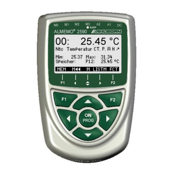
1 Operating Controls
Table of Contents
2 Contents
3 General
Warranty
Scope of Delivery
Waste Disposal
4 Safety Instructions
Special Notes on Use
Handling Batteries / Rechargeable Batteries Correctly
5 Introduction
Functions
Sensor Programming
Measuring Operations
Process Control
6 Initial Commissioning
7 Power Supply
Battery Operation and Supply Voltage Monitoring
Mains Operation
External DC Voltage Supply
Sensor Supply
Switching on / OFF, Reinitialization
Data Buffering
8 Connecting the Sensors / Transducers
Sensors / Transducers
Measuring Inputs and Additional Channels
Potential Separation
9 Display and Keypad
Display and Menu Selection
Measured Value Display and Status Symbols
Function Keys
Function Selection
Data Input
Keypad Locking
10 Menu Selection
11 Measuring Menus
Menu Sensor Display
Selecting a Measuring Point
Measured Value Correction and Compensation
Set Measured Value to Zero
Sensor Adjustment for Dynamic Pressure Probes
Sensor Adjustment for Chemical Sensors and Probes
Temperature Compensation
Atmospheric Pressure Compensation
Cold Junction Compensation
Differential Measurement
Measuring Points List
User Measuring Menu U1 Data Logger
User Menus
Functions
Menu Configuration
12 Function Menus
Maximum, Minimum, Individual Values Memory
Averaging
Smoothing Meas Values by Means of a Sliding Average
Averaging over Individual Manual Meas Operations
Averaging over Time
Averaging over the Cycle
Averaging over Measuring Points
Volume Flow Measurement
Array Measuring Option VN
Two-Point Adjustment with Setpoint Entry
Scaling
Data Logger Functions
Internal Data Memory
Memory Connector with SD-Card
Date and Time-Of-Day
Once-Only Output / Saving of All Measuring Points
Cyclic Output / Saving of All Measuring Points
Numbering of Measuring Operations
Memory Space, Memory Output, Clearing the Memory
Scanning Configuration
Starting and Stopping Measuring Operations
13 Sensor Programming
Selecting the Input Channel
Measuring Point Designation
Averaging Mode
Locking the Sensor Programming
Limit Values
Scaling, Decimal Point Setting
Correction Values
Changing the Units
Selecting the Measuring Range
Function Channels
Special Meas. Ranges ,Linearization ,Multi-Point Calibration
Special Functions
Print Cycle Factor
Actions in the Event of a Limit Value Being Exceeded
Analog Start and Analog End
Minimum Sensor Supply Voltage
Output Function
Reference Channel 1
Reference Channel 2 or Multiplexer
Element Flags
14 Device Configuration
Device Designation
Language
Illumination and Contrast
Interface, Device Address, and Networking
Baud Rate, Data Format
Atmospheric Pressure Compensation and Temperature Compensation
Hysteresis
Operating Parameters
15 Output Modules
Data Cables
Relay-Trigger Modules
Analog Outputs
16 Trouble-Shooting
17 Declaration of Conformity
18 Appendix
Technical Data
Product Overview
19 Index
Advertisement
Quick Links
1
Sensor Programming
2
Measuring Operations
Download this manual
____________________________
Operating instructions
Universal measuring instruments and
data loggers
®
ALMEMO
2590-2A/-4AS
V3.4
21.10.2021
www.ahlborn.com
Table of
Contents
Previous
Page
Next
Page
1
2
3
4
5
Advertisement
Table of Contents
Need help?
Do you have a question about the ALMEMO 2590-2A and is the answer not in the manual?
Ask a question
Questions and answers
Related Manuals for Ahlborn ALMEMO 2590-2A
Measuring Instruments Ahlborn ALMEMO 2390-5 Operating Instructions Manual
Multifunction measuring instrument with data logger option (60 pages)
Measuring Instruments Ahlborn ALMEMO 2590-2 Operating Instructions Manual
Universal measuring instruments and data loggers (76 pages)
Measuring Instruments Ahlborn MA2790BTFV Operating Instructions Manual
Wireless sensor link ma2790btfv with almemo 2790 and sensor module (32 pages)
Measuring Instruments Ahlborn ALMEMO 2490-1 Operating Instructions Manual
Universal measuring instruments (40 pages)
Measuring Instruments Ahlborn ALMEMO 2490-2 Operating Instructions Manual
Universal measuring instruments (40 pages)
Measuring Instruments Ahlborn ALMEMO 2470-1S Operating Instruction
Universal measuring instruments with color display (48 pages)
Measuring Instruments Ahlborn ALMEMO 2450-1L Operating Instructions Manual
Universal measuring instrument (24 pages)
Measuring Instruments Ahlborn ALMEMO 204 Operating Instructions Manual
Special measuring instrument for digital sensors (72 pages)
Measuring Instruments Ahlborn ALMEMO 202-S Operating Instructions Manual
V7 special measuring instrument for digital sensors (76 pages)
Measuring Instruments Ahlborn ALMEMO 2290-4 V5 Operating Instructions Manual
Multifunctional measuring instruments with option data logger (48 pages)
Measuring Instruments Ahlborn ALMEMO 2590-4AS Operating Instructions Manual
Universal measuring instruments and data loggers (80 pages)
Measuring Instruments Ahlborn ALMEMO 2490-1A Operating Instructions Manual
Universal measuring instruments (36 pages)
Measuring Instruments Ahlborn ALMEMO 2290-2/3 Operating Instructions Manual
(44 pages)
Measuring Instruments Ahlborn ALMEMO 2450-1 Operating Instructions Manual
Universal (32 pages)
Measuring Instruments Ahlborn ALMEMO 2390-3 Operating Instructions Manual
Universal measuring instrument (24 pages)
Measuring Instruments Ahlborn ALMEMO 2390-1 Operating Instructions Manual
Universal measuring instrument (20 pages)
This manual is also suitable for:
Almemo 2590-4as
Table of Contents
Print
Rename the bookmark
Delete bookmark?
Delete from my manuals?
Login
Sign In
OR
Sign in with Facebook
Sign in with Google
Upload manual
Upload from disk
Upload from URL


Need help?
Do you have a question about the ALMEMO 2590-2A and is the answer not in the manual?
Questions and answers