
Related Manuals for Ahlborn ALMEMO 2290-4 V5


Summary of Contents for Ahlborn ALMEMO 2290-4 V5
- Page 1 Operating Instructions Multifunctional Measuring Instruments ® ALMEMO 2290-4 with Option Data Logger V1.3 04.12.2003 ALMEMO 2290-4...
-
Page 2: Table Of Contents
Table of Contents Operating Instructions Multimeter ® ALMEMO 2290-4 with Option Data Logger ® For reference with the ALMEMO Manual Table of Contents Page INTRODUCTION Function Range Operating Controls INITIAL OPERATION POWER SUPPLY Operation with Battery and Rechargeable Battery External Voltage Supply Switch On/Off, Reinitialisation CONNECTION OF THE TRANSDUCERS Transducers... - Page 3 Table of Contents Page MEASUREMENT Continuous Measurement of a Measuring Point 7.1.1 Selecting the Measured Value and Measuring Point 7.1.2 Memory for Momentary Values 7.1.3 Memory for Peak Values 7.1.4 Smoothing by Sliding Averaging 7.1.5 Averaging 7.1.6 Volume Flow Measurement 7.1.7 Setting the Meas.
-
Page 4: Introduction
ALMEMO connector ® system, which has been patented by Ahlborn GmbH. The intelligent ALMEMO connector provides important advantages with regard to the connection of sensors and peripherals as all parameters are stored in an EEPROM within the connector. - Page 5 Functions SENSOR PROGRAMMING ® The measuring channels are automatically programmed by the ALMEMO connectors of the sensors. However, the user can easily complete or modify the programming via keypad or via interface. Measuring Ranges There are corresponding measuring ranges for sensors with a non-linear characteristic such as 10 thermocouple types, Ntc and Pt100 sensors, infrared sensors, and flow sensors (rotating vanes, thermoanemometers, pitot tubes).
- Page 6 Functions Scaling The base value and the factor allow for a further scaling of the corrected measured value of each measuring channel for zero point and slope (gain). The decimal point position can be set by the exponent. By setting to zero and entering the nominal value the scaling values can be automatically calculated.
- Page 7 Functions Memory for Momentary Values The measured value can be frozen by the push of a button (hold function). Maximum and Minimum Value Each measurement involves an acquisition and storing of the maximum and minimum value. These values can be displayed, printed or cleared. Average Value of a Channel A manual averaging over a particular period or over single measurements is available for the selected channel.
- Page 8 Functions Conversion Rate ® With ALMEMO devices, all measuring points can be continuously scanned with the conversion rate (2.5 or 10 meas./s). It is also possible to store all measured values in the memory and/or to perform an output via the interface. Data Memory (Option S) All measured values or alarm values only can manually, cyclic or by using the conversion rate be stored in a 30kB internal, buffered RAM, which is sufficient...
-
Page 9: Operating Controls
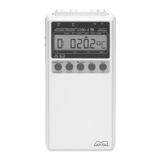
Operating Controls 1.2 Operating Controls (1) ON/OFF Switch ( 3 ) down (2) Measuring Inputs M0, M1 ® M0, M1 for all ALMEMO sensors M2 to M7 additional channels (3) Output Sockets A1, A2 A1 V24 Interface (ZA 1909-DK5) V24 Fiber Optics (ZA 1909-DKL) Ethernet (ZA 1945-DK) Centronics (ZA 1936-DK) RS 422 (ZA 5099-NVB) - Page 10 Operating Controls START/ STOP HOLD (2) FUNCTION KEYS PROGR CLEAR PROGR, +/-, for entering programming values PROGR, CLEAR clear data, set meas. value to zero PROGR, calibrate measured value START/ STOP cyclic measuring point scan select measuring point HOLD select measuring point, hold select measuring functions max value (Hi) min value (Lo)
-
Page 11: Initial Operation
Initial Operation 2. INITIAL OPERATION 1. Connect transducers to the sockets M0 and M1 (2), see 4. 2. Ensure power supply with 9V battery or mains adapter, see 3.1, 3.2. 3. For switching on move the slide switch (1) on the left side of the unit to the upper position, see 3.3. -
Page 12: Power Supply
Power Supply 3. POWER SUPPLY The following options are available for the power supply of the instrument: 9V battery IEC 6 F22 ZB 2000-B9 9V rechargeable battery, as above with charger unit integrated in plug ZB 2000-A9, ZB 2000-LS Mains adapter 12V/200mA ZB 2290-NA External power supply, connecting cable ZB 2290-UK... -
Page 13: External Voltage Supply
Power Supply Tips regarding correct handling of batteries: Do not leave used batteries in the instrument! Remove batteries from the instrument if it is not used for a long period. Risk to health and instrument failure can result from leaking batteries! Therefore, only use leak-proof batteries. -
Page 14: Switch On/Off, Reinitialisation
Power Supply 3.3 Switch On/Off, Data Storage, Reinitialisation The ON/OFF switch (1) on the left side of the device has three positions: down: For switch-on the slide switch (1) on the left side must be moved upwards. The device is switched off when the slide switch s moved to the lower position. Data Storage When the instrument is switched off the real time clock continues its operation and the stored data is maintained as long as the available voltage of the 9V... -
Page 15: Connection Of The Transducers
Connection of the Transducers 4. CONNECTION OF THE TRANSDUCERS ® ® Any ALMEMO sensors can be connected to the ALMEMO input sockets (2) M0 and M1. For connecting existing sensors it is only necessary to connect a ® corresponding ALMEMO connector. -
Page 16: Display And Keypad
Display and Keypad ® Both analogue inputs of the ALMEMO 2290-4 are electrically isolated by using photovoltaic relays and a potential difference of 50V DC or 60V AC, at maximum, is permissible between them. However, sensors combined within one connector and sensors with an own power supply are electrically connected to each other and must, therefore, be operated in isolation. - Page 17 Display and Keypad Double Display for Temperature and Humidity If a double sensor for temperature and humidity is connected to socket M0 the display can be switched to display both variables. To achieve this, the channel M2 for humidity must be selected and key M/ must be pressed longer HOLD than one second.
-
Page 18: Function Selection And Activation
Display and Keypad 5.2 Function Selection and Activation After a reinitialisation (see 3.3) the function group 1 is selected (see below) and, at first, the functions max value and min value are available with key F1, and the measuring range is available with key F2. However, in addition to these basic ®... - Page 19 Display and Keypad Activation of Function Groups As shown in the previous table it is possible to set 10 different function groups that release the corresponding functions (grey background). The applications range from an almost entirely locked instrument to the release of all functions. F Group Application MEASUREMENT: Locked: no input, only single measuring point scan,...
-
Page 20: Keypad
Display and Keypad In the display the function value is indicated next to the function abbreviation. If sensor parameters are indicated the channel number will also be included: Abbr. Abbr. Meas. Functions Programm. Functions d-1 DM Display Mode 1: 127.3MH 1: NiCr R Max Value (Hi) Range... -
Page 21: Data Entry
Display and Keypad PROGR If the key is pressed for longer than one second a digit or an abbreviation will flash in the display, i.e. the instrument is in edit mode and the designations below the keys are valid. Then, the keys +/-, PROGR available for changing the input digit, the key operates as cursor key... -
Page 22: Sensor Programming
Sensor Programming 6. SENSOR PROGRAMMING ® As all ALMEMO instruments contain the whole sensor programming stored in ® the ALMEMO connector plug, the user does not usually need to perform any programming. Only if, for example, sensor errors must be corrected or existing sensors must be scaled or limit values need to be specified the comprehensive programming options have to be used. - Page 23 Sensor Programming Function RANGE ´BE´ 1: N i C r Selection by key F2... Example : chann. M1, range NiCr-Ni Change meas. range: ... or ... , PROGR PROGR Transducer Connector / Meas. Range Dim Display Cable / Sensor P104 Pt100-1 ZA 9000-FS -200.0...
- Page 24 Sensor Programming Transducer Conn. / Cable Meas. Range Dim Display Ir 4 Infrared 4 ZA 9000-FS -30.0... +100.0 °C Ir 6 Infrared 6 ZA 9000-FS 0.0... +500.0 °C S120 Snap-on head Normal 20 FV A915-S120 0.30... 20.00 S140 Snap-on head Normal 40 FV A915-S140 0.40...
-
Page 25: Changing The Dimension
Sensor Programming Switch-off, i.e. deactivation of a programmed measuring channel Function: RANGE ´R´ Keys: PROGR CLEAR After switch-off the measured value is no longer indicated, queried or provided as output. However, the programming is still maintained. Re-activation of the measuring channel: Function: RANGE ´R´... -
Page 26: Limit Values
Sensor Programming 6.4 Limit Values Two limit values (MAX and MIN) can be programmed for each meas. channel. An exceeding of limit values is handled as a fault, similar to an exceeding of meas. range limits and sensor breakage. The arrow ALARM will appear in the display and the alarm relays respond and, in format alarm printout, the alarm values will be output (s. -
Page 27: Scaling, Decimal Point Setting
Sensor Programming 6.6 Scaling, Decimal Point Setting For indicating the electrical signal of a sensor as a measured value of a physical variable it is, in most cases, necessary to set a decimal point shift, a zero point shift and to perform a multiplication with a factor. The functions EXPONENT ´EX´, BASE´BA´... -
Page 28: Locking The Programming Of The Sensor
Sensor Programming The sensor is then brought to a defined nominal value (boiling water, known weight etc.) and the nominal value is entered. For this purpose the key PROGR must twice be pressed long (approx. 1 sec.) until the first digit of the measured value flashes. -
Page 29: Measurement
Continuous Measurement of a Measuring Point 7. MEASUREMENT ® The measuring instruments ALMEMO 2290-4 provides the following options for the acquisition of measuring data: 1. Continuous measurement of a selectable meas. point, see 7.1 and man. 6.4. Output of measuring data to the analogue output, see 8. and man. 5.1.1. 2. -
Page 30: Memory For Momentary Values
Continuous Measurement of a Measuring Point 7.1.2 Memory for Momentary Values For fixing a measured value at a certain point in time, e.g. for an easier evaluation, the key M / HOLD must be operated again in function MEAS.VALUE. This hold function is indicated in the display by an arrow ´MEM´. The memory for momentary values can be cleared by pressing the key M / HOLD again or by selecting another function. -
Page 31: Averaging
Continuous Measurement of a Measuring Point 7.1.5 Averaging The average value of the measured value is required for various applications: e.g. - the average flow velocity in a ventilating channel - smoothing of a largely varying measured value (wind, pressure etc.) - hourly or daily average values of weather data (temp., wind etc.) - as above, of consumption values (current, water, gas etc.) The average value of a measured value... - Page 32 Continuous Measurement of a Measuring Point averaging mode of the selected channel ´StStP´ no cyclic measuring point scan (cycles stopped) no continuous measuring point scan (no C in conversion rate) 1. Select function AVERAGE VALUE ´AV´ with key F1. 2. Clear average value using the keys 1: - - - - PROGR CLEAR...
-
Page 33: Volume Flow Measurement
Continuous Measurement of a Measuring Point 7.1.6 Volume Flow Measurement For determining the volume flow VF in ventilating ducts, the average flow velocity ¯ v must be multiplied with the cross-sectional area CS: VF = ¯ v 0.36 VF = m /h, ¯... -
Page 34: Setting The Meas. Val. To Zero, Zero Pt Corr., Sensor Adjustment
Continuous Measurement of a Measuring Point 7.1.7 Set Meas. Val. to Zero, Zero Pt Corr., Sensor Adjustmt Setting Measured Value to Zero The user can zero the measured value at certain locations or at certain times in order to check the deviation from this reference value. The indicated measured value is, by the following key combination, stored as base value and, as a result, set to zero. -
Page 35: Atmospheric Pressure Compensation
Continuous Measurement of a Measuring Point Sensor Adjustment For some sensors special functions are available in this context: 1. With pH probes, if the two keys START/STOP and F2 are pressed during switch-on, the locking is only temporary, i.e. until the device is switched off and set to 3. An undesired adjustment can then be avoided. -
Page 36: Temperature Compensation
Single Measuring Point Scan 7.1.9 Temperature Compensation Sensors with measured values that are strongly depending on the temperature of the measuring medium are, in most cases, equipped with a specific temperature sensor and the instrument will automatically perform a temperature compensation (see measuring range list 6.2 ´w. TC´). However, dynamic pressure probes and pH probes are also available without a temperature sensor. -
Page 37: Cyclic Measuring Point Scan
Cyclic Measuring Point Scan 7.3 Cyclic Measuring Point Scan (see manual 6.5.1.2) For cyclic measuring point scans the print cycle must be programmed (s. 7.3.1/2). The measurement is started with the key START/ STOP and the arrow ´START´ will be continuously on. If a peripheral device is connected, the measured values are provided as a cyclic output and, in addition, the arrow ´COM´... -
Page 38: Time And Date
Data Memory 7.3.2 Time and Date ® The ALMEMO 2290-4 is equipped with a real time clock with date function for recording the measuring time. It has a device battery so the time and date are maintained after a switch-off. Function TIME ´TM´... -
Page 39: Memory Connector
Data Memory 7.4.1 Memory Connector ® The ALMEMO 2290-4 is the first device that allows connecting external ® ALMEMO EEPROM Memory Connectors ZA 1904-SS with capacities of 128kB or 256kB (25,000 or 50,000 measured values). These memories do not require a battery to keep stored data available. They can be removed, sent away and, independent from the device they can be evaluated on a computer by means of a readout interface (ZA 1409-SLK). -
Page 40: Data Acquisition
Data Memory 7.4.2 Data Acquisition All single measuring point scans and all measuring point scans that are performed in the print cycle are generally stored in the memory. If only alarm values (e.g. exceeding of limit values) should be stored, the output format alarm ´UA´... -
Page 41: Analogue Output
Analogue Output The following key functions are available during the output: START/ STOP Stop of the automatic memory output HOLD Output of individual measured values START/ STOP Start of the automatic memory output CLEAR Cancelling the automatic memory output Clear Memory the message ´SClr´... -
Page 42: Digital Data Output
Digital Data Output 9. DIGITAL DATA OUTPUT The serial interface can be used to completely program the instrument and sensors or to query the programming (see man. 6.). Furthermore, it is possible, as described in sections 7.2 and 7.3, to provide outputs of manual and cyclic measurements online, or offline after a recording (see 7.4), to a printer or computer. -
Page 43: Manual Data Output
Digital Data Output applications (s. man. 6.1). If only alarm values shall be printed at a cyclic measuring point scan, the format Alarm must be set. The output format is indicated in function baud rate ´BR´ by a letter between the output channel ´U´... -
Page 44: Device Address And Networking
Digital Data Output Function Ab Ke Printout AVERAG. MODE AM F2 01:NiCr +0123.4 -0012.0 +0000.0 °C 1.0000 E+0 STSTOP CROSS SECTION CS F2 CROSS SECT: 01: 00078 cm2 DIAMETER: 00100 mm DIAMETER DN F2 CROSS SECT: 01: 00078 cm2 DIAMETER: 00100 mm ANALOG START AS F2 ANALOGSTART:01: +0000.0 °C ANALOG END... -
Page 45: Troubleshooting
Troubleshooting 10. TROUBLESHOOTING ® The measuring instruments ALMEMO 2290-4 can be configured and programmed in many different ways. They allow for a connection of many different sensors, additional measuring instruments, alarm signalisers and peripheral devices. Due to the large variety of options it is possible that, under certain conditions, they do not perform as the user would expect. -
Page 46: Electromagnetic Compatibility
Electromagnetic Compatibility Test the data transmission by using a terminal (AMR-Control, WIN-Control, DATA-Control, WINDOWS Terminal): Address the device with its device number Gxy (see manual 6.2.1), query the programming by P15 (see manual 6.2.3), only check the sending line by cycle input via command Z123456 and control in the display. -
Page 47: Appendix
Appendix Technical Data (see also manual 2.2) Measuring Inputs: ® ® 2 ALMEMO sockets for ALMEMO flat connector Measuring channels: 2 primary channels, electrically isolated, 6 addit. chann. for double sensors and funct. chann., Sensor voltage supply: Battery: 7...9V, max. 70mA Mains adapter: approx. - Page 48 Appendix ALMEMO 2290-4...
Need help?
Do you have a question about the ALMEMO 2290-4 V5 and is the answer not in the manual?
Questions and answers