
Related Manuals for Ahlborn ALMEMO 6290-7B


Summary of Contents for Ahlborn ALMEMO 6290-7B
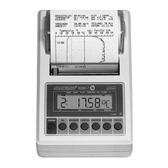
- Page 1 Operating Instructions Measuring Instrument Printer with Built-In ® ALMEMO 6290-7B V1.3 18.03.2004 ALMEMO 6290-7B...
-
Page 2: Table Of Contents
Table of Contents Operating Instructions Measuring Instrument with Built-In Printer ® ALMEMO 6290-7B ® For Reference with the ALMEMO Manual Table of Contents Page INTRODUCTION Function Range Front Operating Controls Rear Operating Controls INITIAL OPERATION POWER SUPPLY Rechargeable Battery Operation Mains Operation External Power Supply Switch On/Off, Reinitialisation... - Page 3 Table of Contents Page SENSOR PROGRAMMING Selecting the Input Channel Selecting the Measuring Range Changing the Dimension Limit Values Correction Values, Sensor Adjustment Scaling, Decimal Point Setting Locking the Programming of the Sensor MEASUREMENT Continuous Measurement of a Measuring Point 7.1.1 Selecting the Measuring Point 7.1.2...
- Page 4 Table of Contents Page TROUBLESHOOTING ELECTROMAGNETIC COMPATIBILITY APPENDIX Technical Data Product Overview Your Contacts ALMEMO 6290-7B...
-
Page 5: Introduction
ALMEMO connector system, which has ® been patented by Ahlborn GmbH. The intelligent ALMEMO connector provides important advantages with regard to the connection of sensors and peripherals as all parameters are stored in an EEPROM within the connector. - Page 6 Functions SENSOR PROGRAMMING ® The measuring channels are automatically programmed by the ALMEMO connectors of the sensors. However, the user can easily complete or modify the programming via keyboard or via interface. Measuring Ranges There are corresponding measuring ranges for sensors with a non-linear characteristic such as 10 thermocouple types, Ntc and Pt100 sensors, infrared sensors, and flow sensors (rotating vanes, thermoanemometers, pitot tubes).
- Page 7 Functions Limit Values and Alarm Two limit values (max and min) can be set for each measuring channel. Alarm contacts that can be individually allocated to limit values can be activated by means of relay output modules if a limit value is exceeded. As a standard, the hysteresis is set to 10 digits, however, it can also be adjusted.
- Page 8 Functions Maximum and Minimum Value Each measurement involves an acquisition and storing of the maximum and minimum value. These values can be displayed, printed or cleared. PROCESS FLOW PROGRAMMING A cyclic measuring point scan with a time-based process flow control is required to register the measuring data of all connected sensors.
- Page 9 Functions diagrams. The limit values are drawn as a line. The print mode allows for the output of the measured values in a list format, or an output of the maximum and minimum values or of the entire programming. MEMORY (Option S) The instrument is, optionally, available with 500 kB memory for 100000 measured values.
-
Page 10: Front Operating Controls
Front Operating Controls 1.2 Front Operating Controls (1) LCD Display (a) Symbols for Operating States Batt. soon empty, charge ▲ CORR Correction of meas. val. ▲ START Measurement in progress CORR START GRAPH LIST RS232 ALARM F ▲ GRAPH Output graphic plot ▲... - Page 11 Front Operating Controls CH ▲ ENTER MEASURE FUNCTION START/STOP PAPER FEED (3) FUNCTION KEYS ENTER, , "#,$, for entering programming values ENTER, Clr clear data, set meas. value to zero ENTER, adjust measured value ▲ select measuring point MEASURE select measuring functions measured value maximum value (Hi) minimum value (Lo)
-
Page 12: Rear Operating Controls
Rear Operating Controls 1.4 Rear Operating Controls (6) MEASURING INPUTS ® ® M1, M2 2 ALMEMO sockets for all ALMEMO sensors M3 to M8 addition. channels for double sensors and function channels (7) OUTPUT SOCKETS RS232 interface cable (ZA 1909-DK) RS232 cable with fiber optics (ZA 1909-DKL) Centronics interface cable (ZA 1936-DK) RS 422 network branch box (ZA 5099-NVB) -
Page 13: Initial Operation
Initial Operation 2. INITIAL OPERATION 1. Connect the transducers to the ALMEMO sockets M1 and M2 (6), s. 4. 2. For battery charging connect mains adapter ZB6290-NA to socket (9), s.3.2. 3. Use key ON/OFF to switch the instrument on, see 3.4. Attention! The keys might be locked by the key switch (8)! 4. -
Page 14: Power Supply
Power Supply 3. POWER SUPPLY 3.1 Rechargeable Battery Operation and Voltage Control For power supply 4 rechargeable NiCd batteries (4.8V/800mAh) are integrated in the instrument. They have a current consumption of ca. 11mA and last, without printing, for an operating time of ca. 90 hours. During continuous operation as a printer, one battery charge lasts ca. -
Page 15: Switch On/Off, Reinitialisation
Power Supply 3.4 Switch On/Off, Reinitialisation The instrument can be switched on by using the key ON/OFF. The instrument can be switched off by using the same key or automatically when the rechargeable battery is discharged. However, the real time clock continuous its operation and all stored data remains available by a buffer battery (see 3.5). -
Page 16: Connection Of The Transducers
Connection of the Transducers 4. CONNECTION OF THE TRANSDUCERS ® ® Any ALMEMO sensors can be connected to the ALMEMO input sockets M1 and M2 of the measuring instrument (6). For connecting existing sensors it is ® only necessary to connect a corresponding ALMEMO connector. - Page 17 Connection of the Transducers The 2 analogue inputs are electrically isolated by using photovoltaic relays and a potential difference of 50V DC or 60V AC, at maximum, is permissible between them. However, sensors combined within one connector and sensors with an own power supply are electrically connected to each other and must, therefore, be operated in isolation.
-
Page 18: Display And Keyboard
Display and Keyboard 5. DISPLAY AND KEYBOARD 5.1 Display ® The display of the measuring device ALMEMO 6290-7B consists of an LCD module with six and a half 7-segment digits, two 16-segment digits, and a battery symbol and seven arrows for indicating the operating status. CORR START GRAPH LIST RS232 ALARM F Special Operating Conditions Segment test of the display... - Page 19 Display and Keyboard After a reinitialisation (see 3.4) the basic functions (bolded in table) for operating the instrument with built-in printer are available by using the keys MEASURE and FUNCTION. More functions are available and can automatically or manually be activated, as required, for correcting measured values and for data transfer.
-
Page 20: Keyboard
Display and Keyboard from those used for the recording of measuring data (see 8.6.1) if a data memory has been integrated (option S). The instruments can be individually configured for any application by setting the functions of the key FUNCTION via interface (AMR-Control) (see man. 6.10.13.3). -
Page 21: Data Input
Display and Keyboard 5.4 Data Entry The programming of numeric parameters is carried out as follows: FUNCTION Select the function by using the key FUNCTION ... The programming is started by using the key ENTER. ENTER The first digit flashes and can be altered. -
Page 22: Sensor Programming
Sensor Programming 6. SENSOR PROGRAMMING ® As all ALMEMO instruments contain the whole sensor programming stored in ® the ALMEMO connector plug, the user does not usually need to perform any programming. Only if, for example, sensor errors must be corrected or existing sensors must be scaled or limit values need to be specified the comprehensive programming options have to be used. - Page 23 Sensor Programming Function RANGE ´R´ FUNCTION 1: N i C r °C Selection with key: Example: channel M1, range NiCr, dimension °C ENTER ENTER Change meas. range: ... or ... , Transducer Connector / Meas. Range Display Cable / Sensor P104 ZA 9000-FS -200.0...
- Page 24 Sensor Programming Transducer Conn./Cable Meas. Range Dim Display Ir 3 Infrared 3 ZA 9000-FS -30.0... +70.0 °C Ir 4 Infrared 4 ZA 9000-FS -30.0... +100.0 °C Ir 6 Infrared 6 ZA 9000-FS 0.0... +500.0 °C S120 FV A915-S120 0.30... 20.00 Snap-on head Normal 20 S140 Snap-on head Normal 40...
-
Page 25: Changing The Dimension
Sensor Programming Switch-off, i.e. deactivation of a programmed measuring channel ENTER Function: RANGE ´R´ Keys: After switch-off the measured value is no longer indicated, queried, or provided as output. However, the programming is still maintained. Re-activation of the measuring channel: ENTER ENTER Function:... -
Page 26: Limit Values
Sensor Programming 6.4 Limit Values Two limit values (MAX and MIN) can be programmed for each measuring channel. The exceeding of the limit values is handled as a fault, similar to the exceeding of the measuring range limits and sensor breakage. The arrow ALARM will appear in the display and the alarm relays will respond (see manual 6.3.9). -
Page 27: Scaling, Decimal Point Setting
Sensor Programming Sensor Adjustment To simplify the correction of sensors for the zero point and, possibly, also the slope (gain), a key combination for an automatic adjustment is available in function MEASURE (see 7.1.3). The corrected measured value is stored as zero point correction and will be set to zero. -
Page 28: Locking The Programming Of The Sensor
Sensor Programming Decimal Point Setting The FACTOR can be programmed in the range -2.0000 to +2.0000. For factors over 2.0 or under 0.2 a corresponding decimal point setting must be considered by entering the EXPONENT. The function EXPONENT ´EX´ allows to shift the decimal point to the left (-) or right (+) as far as it can be indicated on the display and printer. -
Page 29: Measurement
Continuous Measurement of a Measuring Point 7. MEASUREMENT ® The measuring instrument with built-in printer ALMEMO 6290-7B provides the following options for the acquisition of measuring data: 1. Continuous measurement of a selectable measuring point, see manual 6.4. Output of measuring data to the analogue output see manual 5.1.1. 2. -
Page 30: Memory For Peak Values
Continuous Measurement of a Measuring Point 7.1.2 Memory for Peak Values From the acquired measured values of each measuring point the highest and lowest value is determined and stored. For indicating the peak values the function MAX VALUE or MIN VALUE must be selected with the key MEASURE and the desired channel must be set. -
Page 31: Atmospheric Pressure Compensation
Continuous Measurement of a Measuring Point Zero Point Adjustment Many sensors must be adjusted at least once or at regular intervals to compensate for instabilities. For this purpose, a specific zero point adjustment is available, in addition to the ´Set Measured Value to Zero´ mentioned above, as some sensors require an additional scaling (e.g. -
Page 32: Measuring Point Scan
Measuring Point Scan 7.2 Measuring Point Scan (see also manual section 6.5) Measuring point scans can be used to acquire, indicate and, in most cases, to document data from the selected measuring point and also from other measuring points. During a measuring point scan the measuring inputs of the active measuring points are, via photovoltaic relays and with the conversion rate, switched to the measuring circuit. -
Page 33: Print Cycle
Measuring Point Scan 7.2.3 Print Cycle At all measurements the print cycle causes a cyclic measuring point scan of all active measuring points and an output of the measured values to a display, printer, memory (option) or interface. The time can be set between 1s and 12h. The print cycle cannot be accessed in PLOT mode. -
Page 34: Sleep Mode
Measuring Point Scan 7.2.5 Sleep Mode As one completely recharged battery only allows for an operating time of 90 hours at maximum (even with large print cycles) it is possible to operate the instrument with the built-in printer in sleep mode for long-term monitoring. Within this power saving mode the device will switch off after each measuring point scan and will automatically switch on for the next measuring point scan after the cycle time has expired. -
Page 35: Digital Data Output
Digital Data Output 8. DIGITAL DATA OUTPUT For data output the ALMEMO 6290-7B measuring instrument with built-in printer has, at first, the integrated thermal printer and then also a serial interface. During a measurement the measured values of all connected sensors are scanned in cycles and, according to the output mode, provided as output (see 8.1). -
Page 36: Print
Digital Data Output Loading the Temperature-Sensitive Paper Only the temperature-sensitive paper that is specified for this printer must be used to ensure high quality printing and safe operation. To remove the cover, pressure must be applied to the grooved surfaces on both sides and the cover must be pulled upwards. -
Page 37: Measured Values And Max And Min Values
Digital Data Output If the function RANGE ´R´ is selected during start, a header with the programming will be printed at the beginning. It is also possible to provide an individual designation in the header (see manual 6.2.4). Printout for cyclic measuring point scan with output of the header: 5.50 1899 ALMEMO 6290-7... -
Page 38: Plot Range
Digital Data Output PLOT 1 (1 diagram with 4 chann. at max.): PLOT 2 (2 diagrams side by side): 8.4.1 Plot Range The plot range must be specified for each channel that has to be plotted, i.e. the start of the plot range must be programmed in function ´PS´ and the end of the plot range must be programmed in function ´PE´. -
Page 39: Paper Feed
Digital Data Output 8.4.2 Paper Feed If the output mode is set to PLOT the paper feed speed can be programmed in the range of 0.03 to 640 mm/h. 9 9.0 0 Paper Feed: Selection with key FUNCTION... The input is carried out within function ´PF´, in mm/h, according to section 5.4. From the paper feed velocity an internal print cycle can be automatically calculated (see 7.2.3) where the measured values are scanned: Print Cycle: PC [s] = 1280 / PV [mm/h]... -
Page 40: Output Via Serial Interface
Digital Data Output 8.5 Output via Serial Interface As an alternative to the built-in printer the measuring data, as well as the entire programming, can also be provided as an output via serial interface to a printer or computer. The necessary interface modules and the connection of the devices are described in the manual section 5.2. -
Page 41: Manual Data Output
Digital Data Output The output format can also be set in the function output mode ´OM´. The three options can be selected by using the key CH▲. For identification purposes the abbreviations ´n´ or ´t´ follow the output channel ´U´: Abbr. -
Page 42: Device Address And Networking
Digital Data Output Function Ab Ky Printout PS F ANALOG START:01: +0000.0 °C PLOT START PE F ANALOG END: 01: +0100.0 °C PLOT END LIMIT VALUE, MAX LH F LV MAX: 01: -0100.0 °C LL F LV MIN: 01: +0020.0 °C LIMIT VALUE, MIN LM F LOCKING... -
Page 43: Data Memory (Option S)
Data Memory 8.6 Data Memory (Option S) With the option S the measuring instrument with built-in printer is equipped with a 500kB data memory for ca. 100,000 measured values. The basic principles ® for storing data in ALMEMO devices are described in section 6.9 of the manual. - Page 44 Data Memory For separating between memory functions and normal functions the arrow ´F´ is indicated in the display. In function MEMORY FREE ´MF´ the free 2 3 4.5 memory space is indicated in kilobytes. By selecting the OUTPUT MODE ´OM´ (see 8.1) every data log can be subsequently output in any output format.
-
Page 45: Memory Output
Data Memory 8.6.2 Memory Output When all parameters of the memory output have been set according to section 8.6.1 the output can be started by using the key START/STOP. The printouts correspond, depending on the output mode of the list of measured values (see 8.3.2), to the line plots (see 8.4) or to the interface logs (see man. -
Page 46: Troubleshooting
Troubleshooting 9. TROUBLESHOOTING ® The ALMEMO 6290-7B measuring instrument with built-in printer can be configured and programmed in many different ways. It allows for a connection of many different sensors, additional measuring instruments, alarm signalisers and peripheral devices. Due to the large variety of options it is possible that, under certain conditions, it does not perform as the user would expect. -
Page 47: Electromagnetic Compatibility
Electromagnetic Compatibility Test the data transmission by using a terminal (AMR-Control, WIN-Control, DATA-Control, WINDOWS Terminal): Address the device with its device number Gxy (see manual 6.2.1), query the programming by P15 (see manual 6.2.3), only check the sending line by cycle input via command Z123456 and control in the display. -
Page 48: Appendix
Appendix Technical Data (see also manual 2.2) Measuring Inputs: ® ® 2 ALMEMO sockets for ALMEMO connector Meas. channels: 2 primary chann. electr. isol., max. 6 addit. channel for double sensors and function channels Sensor voltage supply: 8 to 10V, max. 70mA Equipment: Display: 6½... -
Page 49: Product Overview
Appendix Product Overview Order No. ® Measuring Instrument with Built-In Printer ALMEMO 6290-7B 2 inputs, max. 8 channels, real time clock, 7 keys, sleep mode, built-in thermal printer, interface that can be cascaded, rechargeable batt 4.8V, 0.8 Ah, 2 rolls temperature sensitive paper, mains adapter 7.5V/450mA MA 6290-7B Option S... -
Page 50: Your Contacts
Appendix Your Contacts Ahlborn Mess- und Regelungstechnik GmbH, Eichenfeldstraße 1-3, D-83607 Holzkirchen, Tel. +49(0)8024/30070, Fax +49(0)8024/300710 Internet: http://www.ahlborn.com, email: amr@ahlborn.com Customer Service/Hotline Mr Florian Plessner, Telephone +49 (0) 8024/300738 ALMEMO 6290-7B... - Page 51 Appendix ALMEMO 6290-7B...
- Page 52 Appendix ALMEMO 6290-7B...
- Page 53 Appendix ALMEMO 6290-7B...
Need help?
Do you have a question about the ALMEMO 6290-7B and is the answer not in the manual?
Questions and answers