
Related Manuals for Ahlborn ALMEMO 5690-1M


Summary of Contents for Ahlborn ALMEMO 5690-1M
- Page 1 ____________________________ Operating instructions English Data acquisition system ® ALMEMO 5690-1M V2.2 04/04/2022 www.ahlborn.com...
-
Page 2: Operating Controls
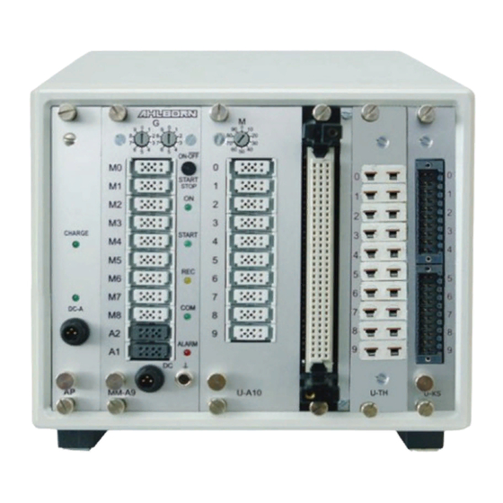
OPERATING CONTROLS (1) Module rechargeable battery (option): (f) Output sockets A1, A2 (a) Connection socket DC-A 12V A1 Interface / optic fiber (ZA1909-DK5/L) Mains adapter (ZB 1212-NAx, 12V, 2.5A) RS 422 (ZA 5099-NVL/NVB) Ethernet (ZA 1945-DK) (b) Check lamps Bluetooth (ZA 1709-BTx) DC-A Mains supply present A2 Network cable (ZA1999-NK5/NKL) - Page 3 1. Operating controls Extension of measuring points with selector switch boards: ® (3) Module U-A10: selector switch board for 10 ALMEMO sockets (j) Code switch M: measuring point x: 10 to 90 for 10 ALMEMO ® (k) Measuring inputs 0 to 9 x0 to x9 sensors x+10 to x+39 max.
-
Page 4: Table Of Contents
CONTENTS Operating controls ..................2 Contents ..................... 4 General ....................... 6 Warranty ..................... 6 Scope of delivery ................7 How to deal with rechargeable batteries (option) ......7 Special notes on use ................. 7 Introduction ....................8 ® Functions of the ALMEMO 5690-1M .......... - Page 5 2. Contents 8.2.2 Trigger inputs ................21 8.2.3 Analog outputs ................21 8.2.4 Connecting peripheral equipment ..........22 8.2.5 Putting into service ............... 22 Technical data RTA5 ................ 22 Operation and configuration ..............23 Combination key ................23 Status LEDs ..................23 Device address and networking ............
-
Page 6: General
GENERAL ® Congratulations on your purchase of this new and innovative ALMEMO data ® acquisition system. Thanks to the patented ALMEMO connector the device configures itself automatically and thanks to the supplied AMR-Control soft- ware its operation should be fairly straightforward. The device can, however, be used with such a wide range of sensors and peripherals and offers so many different special functions. -
Page 7: Scope Of Delivery
3. General 3.2 Scope of delivery When you unpack the device check carefully for any signs of transport dam- age and that delivery is complete: ® Measuring instrument ALMEMO 5690-1M, Mains adapter ZB 1212-NAx 12V/2.5A, these operating instructions, In the event of transport damage please retain the packaging material and in- form your supplier immediately. -
Page 8: Introduction
INTRODUCTION The data acquisition module ALMEMO ® 5690-1M is a new member in our family of unique measuring devices - all equipped with Ahlborn's patented AL- MEMO ® connector system. The intelligent ALMEMO ® connector offers deci- sive advantages when connecting sensors and peripherals because all pa- rameters are stored in an EEPROM located on the connector itself;... -
Page 9: Sensor Programming
4. Introduction of connecting a rechargeable battery module. 4.1.1 Sensor programming The measuring channels are programmed, completely and automatically, by the ALMEMO ® connectors. However, the user can easily supplement or modi- fy this programming via the interface. Measuring ranges Appropriate measuring ranges are available for all sensors with a non-linear characteristic, e.g. -
Page 10: Measuring Operations
4. Introduction bration; (see 11). Scaling The corrected measured value on each measuring channel can also be further scaled in terms of zero-point and gain - using the base value and factor. The decimal point position can be set by means of the exponent function. The scal- ing values can be calculated automatically by setting to zero and entering the nominal setpoint. -
Page 11: Process Control
4. Introduction tion is provided for humidity sensors, dynamic pressure sensors, and O sen- sors. On infrared sensors the parameters for zero-point correction and gain correction are used as the background temperature and the emissivity factor. Maximum and minimum values Each measuring operation acquires and stores the maximum and minimum values with date and time-of-day. - Page 12 4. Introduction Measured value memory To save measured values there are two alternative methods. Option S is a 512-KB non-volatile EEPROM, sufficient for up to 100,000 measured values. This memory can be organized and configured in linear or ring form. Output is via the interface.
-
Page 13: Initial Commissioning
INITIAL COMMISSIONING 1. Sensor connection : Plug in sensor at sockets M0 to Mxx (2c); see Sec. 7. Connect mains adapter at socket DC (2g); s. Sec. 6.1. 2. Power supply : Press the ON key (2e); see Section 6.5. 3. -
Page 14: Power Supply
POWER SUPPLY Power can be supplied to the instrument in any of the following ways : Mains adapter 12V/2.5A (ZB 1212-NAx) Electr. isol. power supply cable, 10 to 30 VDC, 0.25 A (ZB 3090-UK) Electr. isol. power supply cable, 10 to 30 VDC, 1.25 A (ZB 3090-UK2) Rechargeable battery module, NiMH 9.6 V / 1600 mAh (ES 5690-AP) See product overview, Annex 14 and the following chapters. -
Page 15: Sensor Supply
6. Power supply thus be left permanently connected to the measuring instrument in buffer mode without risk of overcharging the batteries. If you prefer not to recharge the batteries, e.g. to prevent the device from warming up during thermocouple measurement, you can connect the mains unit to the DC socket (2g). ... -
Page 16: Connecting The Transducers
CONNECTING THE TRANSDUCERS Virtually any ALMEMO ® sensor can be connected to the input sockets on AL- MEMO ® modules types (2) and (3). To connect your own existing sensors you simply need the appropriate ALMEMO ® connector. Other compact modules are described below. -
Page 17: Extending The Measuring Points
7. Connecting the transducers itself makes more sense. On the measuring circuit board this gives the following channel assignment: 7.3 Extending the measuring points To extend the measuring points up to 9 passive selector switch boards can be used; however, the total number of measuring channels is limited to maxi- mum 100. -
Page 18: Potential Separation
7. Connecting the transducers nals A, B, C, D, in the same way as any standard ALMEMO ® connector; (see Manual 4.1). Sensors requiring a power supply or an ALMEMO ® connector with special interface circuitry (e.g. humidity sensors, rotating vanes, etc.) cannot be connected in this way. - Page 19 7. Connecting the transducers The analog inputs are electrically isolated from one another by means photo- voltaic relays. A new feature on this device is the additional separation of the measuring inputs from CPU and power supply. Between all inputs and outputs (even the analog output cables which are not electrically isolated) the maxi- mum potential difference permitted is 50 V.
-
Page 20: Relay Trigger Analog Module
RELAY TRIGGER ANALOG MODULE ® The universal trigger output interface specially provided for ALMEMO 5690 systems is relay trigger analog module ES 5690-RTA5 with up to 10 interface elements (4 semiconductor relays and 2 trigger inputs as standard but option- ally up to 10 semiconductor relays or 10 electrically isolated analog outputs). -
Page 21: Relays
8. Relay trigger analog module ® electrically isolated, including ALMEMO clamp connectors. 8.2.1 Relays The output relays are driven by means of interface commands or in the event of alarm automatically by the system. (see Manual, 6.10.10) The function of each relay can be freely set by configuration. -
Page 22: Connecting Peripheral Equipment
8. Relay trigger analog module any partial measuring ranges. (see 12.4.4, 12.6.3) 8.2.4 Connecting peripheral equipment ® Peripherals can be connected via the supplied ALMEMO screw connectors according to the following arrangements. P0/1 P2/3 P4/5 P6/7 P8/9 Terminals Relay Relay Analog (opt.) Analog (opt.) Trigger... -
Page 23: Operation And Configuration
OPERATION AND CONFIGURATION Data acquisition system ALMEMO ® 5690-1M has only a few operating con- trols; it is operated mainly via a PC. 9.1 Combination key The first function of the one and only key ON/OFF-START/STOP (2e) on the mas- ter measuring circuit board has already been described in Section 6.5. -
Page 24: Configuration
9. Operation and configuration necessarily in the event of interruption to the power supply. 9.4 Configuration For the purposes of programming and configuration the supplied AMR-Control software is ideally suited. This can be used to modify the the programming of the sensors and to configure the process control. -
Page 25: Measured Data Acquisition
10. MEASURED DATA ACQUISITION Measured data acquisition can be performed in basically two ways : 1. Perform measurement online and transfer data to the PC immediately (no device-internal memory required). 2. Perform measurement offline, i.e. the data is first saved to the device memory (option S) or to an external memory connector with multimedia card and then transferred to the PC later. -
Page 26: Sleep Mode
10. Measured data acquisition 10.2.1 Sleep mode For long-term monitoring involving large measuring cycles where power is supplied by rechargeable or normal battery the measuring system can also be operated in sleep mode. In energy-saving sleep mode the measuring instru- ment switches off after each measuring point scan and switches on again au- tomatically after the cycle expires ready for the next measuring point scan. -
Page 27: Memory Connector With Memory Card
10. Measured data acquisition 10.2.3 Memory connector with memory card Another convenient feature for data recording without option S is provided by the newly developed memory connector (ZA 1904-SD) with a conventional memory card. The memory card measured data is written to it via the memory connector in table mode and in standard FAT16 format. - Page 28 10. Measured data acquisition ground. When plugging in the connector make sure that the card remains latched in position ! To check that the memory connector is functioning properly there is an LED incorporated in the end of the handle; this indicates the following states : ●...
-
Page 29: Special Measuring Ranges, Linearization, Multi-Point Calibration
11. SPECIAL MEASURING RANGES, LINEARIZA- TION, MULTI-POINT CALIBRATION Thanks to the new ALMEMO® special connectors with extra memory for addi- tional data (bigger EEPROM, code E4) the following tasks can now be per- formed for the first time with great elegance : 1. -
Page 30: Troubleshooting
12. TROUBLESHOOTING Data acquisition system ALMEMO ® 5690-1M can be configured and pro- grammed in many versatile ways. It is suitable for connecting a wide variety of very different sensors, additional measuring instruments, alarm signaling de- vices, and peripheral equipment. Given these numerous possibilities the de- vice may in certain circumstances not behave quite as expected. - Page 31 12. Troubleshooting Error: Data transmission in the network does not function. Remedy: Check to ensure that all devices are set to different addresses. Address all devices individually via the terminal with command ´Gxy´. Addressed device is OK if at least ´y CR LF´ is returned as echo. If transmission is still not possible, unplug the networked devices.
-
Page 32: Declaration Of Conformity
13. DECLARATION OF CONFORMITY... -
Page 33: Appendix
14. APPENDIX 14.1 Technical data Measuring inputs : Master meas. circuit board MM-A9: 9 ALMEMO sockets, suitable for ALMEMO flat connectors ® ® Measuring channels: 9 primary channels, electrically isolated, maximum 31 additional channels for double sensors and function channels A/D converter : Delta - sigma, 24-bit, 2.5 / 10 / 50 / 100 measuring operations per second, adjustable 1 to 100... - Page 34 14. Appendix Product overview Order no. Data acquisition system ALMEMO 5690-1M ® 9 inputs, maximum 40 channels, 2 outputs, cascadable interface, real-time clock, 1 key, mains adapter 12 V / 2.5 A in 19-inch desktop housing, 12 DU, 1 slot MA 56901M09TG1 in 19-inch desktop housing, 32 DU, 6 slots MA 56901M09TG3...
-
Page 35: Index
15. INDEX Accessories ......34 Module U-KS ....... 3 additional channels ....16 Module U-MU ......3 AMR-Control ......12 Module U-TH ....... 3 calibration data management ..29 networking ........23 Check lamps ........ 2 Offline measurement ....25 code switch ........ -
Page 36: Your Contact
YOUR CONTACT AHLBORN Mess- und Regelungstechnik GmbH Eichenfeldstraße 1 83607 Holzkirchen Germany internet : http://www.ahlborn.com e-mail : amr@ahlborn.com Despite great care, incorrect information cannot be ruled out. Technical changes are reserved.