Table of Contents
Advertisement
Advertisement
Table of Contents

Related Manuals for HAKO Scrubmaster B100R


Summary of Contents for HAKO Scrubmaster B100R
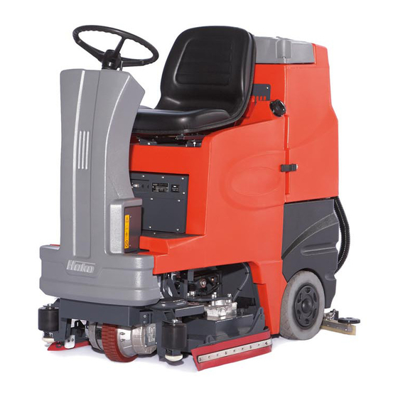
- Page 1 Instruction Manual Scrubmaster B100R (7300.10/.20)
-
Page 2: Preface
Please be advised explicitly that we Intended use cannot accept any legal issues out of Dear customer, It is our desire that the The Scrubmaster B100R is a Scrubbing the contents of this manual. good characteristics of the Scrubmaster Machine conceived for the wet cleaning... -
Page 3: Notes On Warranty
Follow unpack- of modifications to the vehicle not au- Hako dealer in accordance with the Bat- ing instructions on shipping pallet. Each thorized by us. The manufacturer is not tery Law §... -
Page 4: Table Of Contents
5.8.3 Changing the brushes ..44 Switching the vehicle on..11 Hako system maintenance. . 32 5.8.4 Checking the sealing strip . . 44 Operation ....11 Proof of maintenance . -
Page 5: Safety Information
Safety information Safety information Safety and Warning Symbols All paragraphs in this manual referring to your personal safety, the safety of your machine and the environment pro- tection are attributed one of the follow- ing warning symbols: Symbol Hazardous for... Description Safety Provisions persons and goods... -
Page 6: General Provisions
• Persons being trained by qualified spare parts! cleaning agent manufacturer. Hako technicians only are autho- • Only open empty recovery tanks. – rised to operate, service and repair Operating information Risk of tipping. -
Page 7: Maintenance Information
• Never lay any metallic objects or nance work must be completed at • It is not permitted to clean the vehicle tools on batteries. - Risk of short cir- your nearest authorized Hako ser- with a pressure washer or steam cuit! vice center. -
Page 8: Information For Protection Of Environment
DIN VDE 0620-1. be agreed on with your authorized • Pay attention that no water or fluids Hako dealer in accordance with the can get on to live machine parts. If Battery Law § 6 and § 8 (BattG). water should penetrate to such... -
Page 9: Labels On The Vehicle
(Fig. 1/4) Company logo (Fig. 1/1) Rating plate (Fig. 1/2) FRONT OF MACHINE Scrubbing tool (Fig. 1/7) Only fill water at max. 50 °C (Fig. 1/3) Type name (Fig. 1/5) Waste water draining hose (Fig. 1/8) Scrubmaster B100R... - Page 10 Safety information Fill level for solution tank (Fig. 1/9) - 1/1 - 1/2 Explosive gases (Fig. 1/10) Fig.1...
-
Page 11: First Operation
Chapter "Mainte- ing is required, set the function se- person sent by your local Hako contract nance". lection switch to the corresponding dealer. Your Hako dealer will be in- field. -
Page 12: Interrupting Operation
First Operation Only use cleaning agents suit- Loading the vehicle Interrupting operation able for the equipment (non- 1. Empty the solution tank and recov- 1. Release the throttle. – The vehicle foaming). We recommend us- ery tank. stops. ing our clean and care prod- 2. -
Page 13: Operation
Chapter 5 Maintenance and Service. Method of operation 3.1.1 General information The Scrubmaster B100R is a floor scrubbing vehicle conceived for the wet cleaning of hard floors. Fig.3... -
Page 14: Scrubbing
The vehicle is provided with the electri- catalogue on our internet site ly raised and the brushes and solution cal power necessary for operation from at www.hako.com for accesso- supply are switched off. batteries (Fig. 3/6). The batteries must ries, such as brushes and suc- The solution tank (Fig. -
Page 15: Solution And Waste Water
Operation 3.1.6 Solution and waste water 1 Solution tank 2 Solution tank filling neck 3 Solution level indicator 4 Solution draining hose 5 Recovery tank 6 Recovery tank locks 7 Waste water draining hose 8 Waste water drain 9 Air intake filter 10 Suction turbine fine particle filter 11 Waste water service access 12 Scrubbing-vacuum tool water con-... - Page 16 Operation Solution tank (Fig. 4/1) of a draining hose. disconnected from the holder and laid to a floor drainage system, for example. The solution tank contains the solution Recovery tank (Fig. 4/5) A reducer can be mounted on the drain- required for the scrubbing operation, ing end to reduce the escaping flow, the solution being made up of water and...
- Page 17 Operation Waste water service access (Fig. 4/11) The waste water service access en- ables access to the inside of the recov- ery tank and, in particular, to the preliminary filter. Scrubbing-vacuuming tool water connection (Fig. 4/12) This water connection supplies solution to the scrubbing-vacuuming tool (op- tion) if connected.
-
Page 18: Brush Head
Operation 3.1.7 Brush head 1 Rotary brush head 2 Side sealing strips 3 Star-sharped knob for side sealing strips Star-sharped knobs for side seal- ing strips 5 Brush cover 6 Rotary brush 7 Waste tank 8 Nozzles 9 Deflector roller, front 10 Circular brush head 11 Circular brush 12 Cover... - Page 19 Operation Rotary brush head (Fig. 5/1) Star-sharped knob for side sealing Waste container (Fig. 5/7) The rotary brush head is lowered and strips (Fig. 5/3) The waste container collects the items raised by means of a servomotor. The swept up by the rotary brushes. The star-sharped knob hold the pivoting arrangement of rods for parallel exten- holders for the side sealing strips in po-...
- Page 20 Operation Covers (Fig. 5/12) The covers must be removed in order to change the circular brushes. Star-sharped knobs for sealing strip (Fig. 5/13) The sealing strips are fixed to the cov- ers by means of star-sharped knobs so that they can be vertically adjusted. Star-sharped knobs for covers (Fig.
-
Page 21: Squeegee
Operation 3.1.8 Squeegee 1 Squeegee 2 Squeegee roller 3 Suction hose 4 Star-sharped knob for squeegee 5 Squeegee sealing strip 6 Deflector roller, rear 7 Deflecting bar 8 Ball-head rod 9 Hanger 10 Angle adjustment 11 Pivoting axle Fig.6... - Page 22 Operation Squeegee (Fig. 6/1) sealing strips are worn out and have to Angle adjustment (Fig. 6/10) be changed. The squeegee is equipped with sealing The angle adjustment is used to set the strips and is lowered and raised by squeegee so that it is held tipped slight- Deflection rollers, rear (Fig.
-
Page 23: Drive And Batteries
Operation 3.1.9 Drive and batteries 1 Throttle 2 Drive motor 3 Energy chain 4 Control unit 5 Batteries 6 Charging plug Fig.7... - Page 24 Operation Throttle (Fig. 7/1) tors the battery charge status. The position of the throttle defines the Batteries (Fig. 7/5) vehicle driving speed. On releasing the throttle, the vehicle decelerates, comes The batteries are installed under the re- to a stop and the parking brake is acti- covery tank and supply power to the vated.
-
Page 25: Operating And Indicator Elements
Operation Operating and indicator elements 3.2.1 Operating panel 1 Indicator field 2 Key switch 3 Horn 4 Direction switch 5 Driving direction indicators 6 Low discharge signal indicator (LDS) / Diagnostic codes 7 Solution dosing 8 Function selection switch 9 Scrubbing-vacuuming tool (option) 10 Operating hour counter 11 Fuses... - Page 26 - to front = forwards vice - to rear = reverse 4 Actuator fault: Inform Hako-Service The indicator field provides a central 5 Vacuum motor fault: Inform Hako- function monitoring facility and indi- Service cates all operating states. 6 Off-aisle wand activated...
- Page 27 Operation Function selection switch (Fig. 8/8) The function selection switch is used to select the required operating mode. Scrubbing-vacuuming tool (Fig. 8/9) The operating modes available for se- lection are (indicated counterclock- This switch is used to activate the wise): scrubbing-vacuuming tool (option).
- Page 28 Operation 1.1.1.1 Operating hour counter (Fig. 8/10) Main fuse (Fig. 8/11) The operating hour counter indicates The main fuse interrupts the entire pow- the number of operating hours currently er supply to the vehicle. In the event of accumulated. faults in the electrical system, the vehi- cle must be shut down by means of the main fuse.
-
Page 29: Seat
Operation 3.2.2 Seat 1 Seat adjustment lever 2 Seat switch Seat adjustment lever (Fig. /1) When the lever is pulled out, the seat can be adjusted to the required posi- tion. Seat switch (Fig. /2) The seat switch prevents the vehicle from being driven without anyone sitting in the seat. -
Page 30: Technical Data
Technical Data Technical Data Unit Circular brush Rotary brush Vehicle length Vehicle height Vehicle width, without squeegee Vehicle width, with squeegee Working width Squeegee width Area coverage, theoretic m²/h 2925 2925 Nominal voltage Power consumption, drive motor (P1) Power consumption, aspirating engine (P1) Power consumption, brush motor (P1) 1 x 1188 2 x 684... - Page 31 Technical Data Noise emission value Unit Max. sound power level (L wAd ) measured at extreme operating conditions in compliance with dB (A) DIN EN 60335-2-72: The sound pressure level (L pA ) (at the ear of the operator) measured according to DIN IEC dB (A) 60335-2-72 under normal working conditions: Measurement inaccuracy (KpA):...
-
Page 32: Maintenance And Service
Maintenance and Hako system maintenance: tem maintenance using spare parts kits. Service • ensures that the Hako vehicle is al- Hako system maintenance II: ways ready for operation (preventive General information (every 500 operating hours)... -
Page 33: Proof Of Maintenance
Maintenance and Service Proof of maintenance Hand-over Hako System Maintenance I Hako System Maintenance II Hako System Maintenance I 250 operating hours 500 operating hours 750 operating hours Upgrading Workshop Stamp Workshop Stamp Workshop Stamp Test drive Hand-over to customer... -
Page 34: Maintenance Plan
Maintenance and Service Maintenance plan Hako system maintenance customer The following maintenance work must be completed by the customer at the in- tervals stipulated. Interval Activity Daily Weekly Check the battery charge Fill the solution tank Empty the recovery tank... - Page 35 Maintenance and Service Hako system maintenance I The following maintenance work must be completed by an authorized Hako service center. Interval Activity Every 250 operating hours Check the recovery tank cover seal Rinse the solution tank draining hose Check the recovery tank draining hose and suction hose...
- Page 36 Interval Activity Every 500 operating hours All maintenance work in accordance with Hako system maintenance I Grease the hinging points on the brush attachment Grease the support wheels on the squeegee Grease the hinging points on the squeegee holder...
- Page 37 Interval Activity Every 1000 operating hours All maintenance work in accordance with Hako system maintenance II Check parking brake Check the key switch, main fuse and horn Check the cable connections Check the seat latching mechanism...
-
Page 38: Battery System
Maintenance and Service Battery system 1 Batteries 2 Battery plug 3 Low discharge signal indicator (LDS) 4 Lock 5 Recovery tank 6 Wiring diagram Batteries may only be handled and changed by properly skilled maintenance person- nel. Fig.10... -
Page 39: Charging Batteries
3. Position the batteries in the battery 88-60-2723 charger and the battery an authorized Hako service tray in accordance with the figure. manufacturer. center. 4. Connect the battery poles to the con- Before starting the vehicle up 5.4.3 Servicing the driving batteries... -
Page 40: Solution Tank
Maintenance and Service Solution tank 1 Solution tank 2 Tank cap 3 Marking 4 Fill level indicator 5 Draining hose 6 Bracket 5.5.1 Filling the solution tank Fill the solution tank (Fig. 11/1) before starting work or as necessary. Park the vehicle on a level floor area. -
Page 41: Recovery Tank
Maintenance and Service Recovery tank 1 Recovery tank 2 Draining hose 3 Draining hose cap 4 Tank cap 5 Flap 6 Plug 7 Recovery tank locks 8 Air intake filter Fig.12... -
Page 42: Emptying The Recovery Tank
Maintenance and Service 5.6.1 Emptying the recovery tank 5.6.2 Cleaning the recovery tank Empty the recovery tank (Fig. 12/1) ev- Clean the recovery tank (Fig. 12/1) ev- ery day or as necessary. ery day or as necessary. 1. Drive to an appropriate disposal 1. -
Page 43: Circular Brush Head
Maintenance and Service 5.7.1 Cleaning the brushes 2. Unhook the brushes by pressing Circular brush head 1. Remove the covers (Fig. 13/2) from them down. the brushes (Fig. 13/1). 3. After cleaning the brushes, hook 1 Brush them back in at the side in the holder 2 Cover (Fig. -
Page 44: Rotary Brush Head
Maintenance and Service Rotary brush head 5.8.1 Cleaning the waste container 2. Remove the knobs (Fig. 14/4), pull Unscrew the latching handles (Fig. 14/ out the brush (Fig. 14/5) and remove 1 Latching handle to enable pivoting 1) and pivot the sealing strip (Fig. 14/2) the bearing cap (Fig. -
Page 45: Squeegee
Maintenance and Service 5.9.1 Cleaning the squeegee 3. Loosen the two star-shaped knobs Squeegee To clean the squeegee (Fig. 15/1), raise and disassemble the squeegee. it, disconnect the suction hose (Fig. 15/ 4. Loosen the fastening device (Fig. 15/ 1 Squeegee 2), loosen the two star-shaped knobs 5) and remove the outer sealing 2 Suction hose... -
Page 46: Adjusting The Squeegee
Maintenance and Service 5.9.3 Adjusting the squeegee Angle Adjustment The angle adjustment is the decisive factor in ensuring that the sealing strips on the squeegee lie evenly on the floor. 1. Park the machine on a level surface and lower the squeegee. 2. - Page 47 Maintenance and Service Height Adjustment The height adjustment is set to 3 mm at the factory. If streaks are produced, de- spite an optimum angle adjustment, the clearance between the rollers and floor must be adjusted by changing the num- ber of washers on the holder.
-
Page 48: Troubleshooting
Vacuum hose clogged or damaged Remove debris or replace vacuum hose Poor scrubbing performance Worn brushes Bürsten drehen oder wechseln Wrong brush or cleaning chemical Hako-Service Debris cought on brushes Remove debris Moving machine to fast Slow down Low battery charge... - Page 49 Maintenance and Service Problem Possible Cause Remedy Inadequate solution flow or Recovery tank full Empty recovery tank no solution to the floor Solution tank empty Fill solution tank Solution lines, valves, filter or spray jets Clean Solution lines, valves, filter or spray jets clogged Machine does not run Emergency stop switch tripped...
- Page 50 Maintenance and Service...
-
Page 51: Ec-Declaration Of Conformity
(s) and / or technical specifica- tion (s) has (have) been respected: Ludger Lüttel declare under our sole responsibility, that the product DIN EN 60335-2-72 Scrubmaster B100R Disk Brush DIN EN 61000-6-2 Type: 7300.10 DIN EN 55012 Scrubmaster B100R Cylindrical Brush Type: 7300.20... - Page 52 Advanced Technology for a Cleaner, Better Environment · · Hako GmbH Hamburger Str. 209-239 D-23843 Bad Oldesloe · +49 4531 806-0 Fax+49 4531 806-338...
Need help?
Do you have a question about the Scrubmaster B100R and is the answer not in the manual?
Questions and answers