Christie M Series Service Manual
Hide thumbs
Also See for M Series:
- User manual (168 pages) ,
- Setup manual (54 pages) ,
- Specifications (12 pages)
Table of Contents
Advertisement
Quick Links
Advertisement
Table of Contents

Subscribe to Our Youtube Channel
Related Manuals for Christie M Series


Summary of Contents for Christie M Series
- Page 1 Service Guide 020-100551-11 M Series...
- Page 2 The warranty does not apply to any product where the serial number has been removed or obliterated. The warranty also does not apply to any product sold by a reseller to an end user outside of the country where the reseller is located unless (i) Christie has an office in the country where the end user is located or (ii) the required international warranty fee has been paid.
-
Page 3: Table Of Contents
Troubleshooting guidelines..........26 M Series Service Guide 020-100551-11 Rev. 1 (01-2019) Copyright 2019 Christie Digital Systems USA, Inc. All rights reserved. ©... - Page 4 Removing the intake and exhaust fans (#5 and #6)......56 M Series Service Guide 020-100551-11 Rev. 1 (01-2019) Copyright 2019 Christie Digital Systems USA, Inc. All rights reserved. ©...
- Page 5 Lens mount components......... . . 86 M Series Service Guide 020-100551-11 Rev. 1 (01-2019) Copyright 2019 Christie Digital Systems USA, Inc. All rights reserved. ©...
- Page 6 Interconnect diagram..........93 M Series Service Guide 020-100551-11 Rev. 1 (01-2019) Copyright 2019 Christie Digital Systems USA, Inc. All rights reserved. ©...
-
Page 7: Introduction
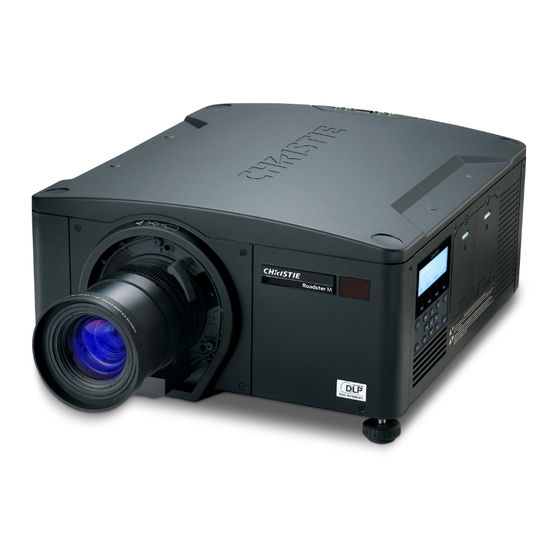
However, due to continuing research all information is subject to change without notice. Christie assumes no responsibility for omissions or inaccuracies. Projector overview The M Series is a family of high resolution video/graphics 3 chip 1080p HD, SXGA+, WUXGA, and WXGA projectors. These projectors are based on next-generation DLP technology provided by Texas ®... -
Page 8: List Of Components
One of the two IR sensors on the projector detect the signal and relay the commands for internal processing. The remote also offers a connector for wired connections to the projector. M Series Service Guide 020-100551-11 Rev. 1 (01-2019) Copyright 2019 Christie Digital Systems USA, Inc. All rights reserved. ©... - Page 9 Turns off the light source and puts the projector in standby. Selects an active or inactive input on any slot. Not supported. M Series Service Guide 020-100551-11 Rev. 1 (01-2019) Copyright 2019 Christie Digital Systems USA, Inc. All rights reserved. ©...
- Page 10 Shows or hides the on-screen display menus. Turns the remote backlight on. Male 3-pin XLR connector for wired option. Lock/unlock the keypad. Battery door. M Series Service Guide 020-100551-11 Rev. 1 (01-2019) Copyright 2019 Christie Digital Systems USA, Inc. All rights reserved. ©...
-
Page 11: Service Guidelines
To ensure you have the correct module and the projector module is replaced correctly, check module markings, parts lists, and the relevant disassembly and replacement procedures. Components must be replaced with exact equivalents or Christie approved replacement parts. Failure to do so may result in unsafe operation. -
Page 12: Important Safeguards
TIP HAZARD! Stacked frames must be secured together using all locking pins. • UV EXPOSURE! Protective UV safety glasses with side shields and Christie approved protective safety clothing must be worn when performing optical adjustments or servicing the product. •... -
Page 13: Ac/Power Precautions
Dispose of bare bulb with packaging according to local area regulations. Related documentation Additional information on the projector is available in the following documents. • M Series Installation and Setup Guide (P/N: 020-101941-XX) • M Series User Guide (P/N: 020-101948-XX) M Series Service Guide 020-100551-11 Rev. -
Page 14: Maintenance And Cleaning
• M Series Product Safety Guide (P/N: 020-102690-XX) • M Series Serial API Commands Technical Reference (P/N: 020-100224-XX) Maintenance and cleaning Maintain the cleanliness of all internal components during any service procedure. All of the projector optics must remain free of contaminants to perform at the level specified. Even a small amount of dust or a fingerprint may degrade the image or cause a noticeable reduction of brightness. -
Page 15: Maintaining The Cooling System
Do not spill liquids of any kind into the projector. Should an accidental spill occur, immediately unplug the projector and have it serviced by a qualified service technician. Power supplies Power supplies are not serviceable. Never open or attempt to service a power supply. Contact Christie for a replacement. M Series Service Guide 020-100551-11 Rev. -
Page 16: Power Cord And Attachments
Dust-free lens tissue, such as: Optowipes (18LAB022), Kim Wipes, or equivalent • For lens only: Lens cleaning solution • Cotton swabs with wooden stems only • Lens cleaning cloth/microfiber M Series Service Guide 020-100551-11 Rev. 1 (01-2019) Copyright 2019 Christie Digital Systems USA, Inc. All rights reserved. ©... - Page 17 3. Gently wipe the surface with a figure-8 motion. Repeat this motion until the blemish is removed. M Series Service Guide 020-100551-11 Rev. 1 (01-2019) Copyright 2019 Christie Digital Systems USA, Inc. All rights reserved. ©...
-
Page 18: Service Setups
If boresight is required, continue to step 4. The adjustment screws (A) on the lens mount affects the corresponding cross-hairs on the test pattern. M Series Service Guide 020-100551-11 Rev. 1 (01-2019) Copyright 2019 Christie Digital Systems USA, Inc. All rights reserved. ©... - Page 19 If the boresight does not appear to be converging to an acceptable level of image quality, or if the lens does not focus over the correct range of throw distances, proceed with step M Series Service Guide 020-100551-11 Rev. 1 (01-2019) Copyright 2019 Christie Digital Systems USA, Inc. All rights reserved. ©...
-
Page 20: Adjusting Convergence
SHOCK HAZARD! Disconnect the product from AC before installing, moving, servicing, cleaning, removing components, or opening any enclosure. • UV EXPOSURE! Protective UV safety glasses with side shields and Christie approved protective safety clothing must be worn when performing optical adjustments or servicing the product. Removing the light engine cover Complete the following procedure to remove the light engine cover. -
Page 21: Adjusting Convergence
Warning! If not avoided, the following could result in death or serious injury. • UV EXPOSURE! Protective UV safety glasses with side shields and Christie approved protective safety clothing must be worn when performing optical adjustments or servicing the product. - Page 22 3. Adjust screw A and B+C to center the color in the cross-hair at the center of the screen. Screw A Screw A Screw B+C Screw B+C M Series Service Guide 020-100551-11 Rev. 1 (01-2019) Copyright 2019 Christie Digital Systems USA, Inc. All rights reserved. ©...
-
Page 23: Adjusting The Fold Mirror
If a corner or edge of the image is missing (after prime lens offset is ruled out), this may indicate the fold mirror has become misaligned with the rest of the optical system, resulting in cropping of the projected image. M Series Service Guide 020-100551-11 Rev. 1 (01-2019) Copyright 2019 Christie Digital Systems USA, Inc. All rights reserved. ©... -
Page 24: Adjusting The Integrator Tilt
Complete the following procedure to adjust the integrator focus lens. 1. Remove the top cover (on page 45). 2. Loosen the two setscrews. Do not loosen the focus lens handle. M Series Service Guide 020-100551-11 Rev. 1 (01-2019) Copyright 2019 Christie Digital Systems USA, Inc. All rights reserved. ©... - Page 25 Service setups 3. Adjust the focus lens by moving the focus lens handle forward or back. 4. Tighten the two setscrews. M Series Service Guide 020-100551-11 Rev. 1 (01-2019) Copyright 2019 Christie Digital Systems USA, Inc. All rights reserved. ©...
-
Page 26: Troubleshooting
Christie technical support for additional help. To aid in service and warranty claims, Christie electronically tracks the serial numbers of all modules within a projector. On the warranty card, record the serial number of the new module installed, as well as the serial number of the defective module. -
Page 27: Normal Power Up (Lcd Keypad And Rear Status Leds)
1 minute and 50 Amber Amber Standby mode seconds to 1 Press and hold minute and 55 Power to turn on seconds projector M Series Service Guide 020-100551-11 Rev. 1 (01-2019) Copyright 2019 Christie Digital Systems USA, Inc. All rights reserved. ©... -
Page 28: Temperature Sensors
1. Open a web browser and type the IP address of the projector into the address bar. M Series Service Guide 020-100551-11 Rev. 1 (01-2019) Copyright 2019 Christie Digital Systems USA, Inc. All rights reserved. ©... -
Page 29: Resolving Problems While Saving An Error Log
7. Once the warning window displays, click OK. Submitting an error log for analysis The interrogator log is saved as an encrypted file and must be sent to Christie technical support for analysis. 1. Attach the log file to an email. -
Page 30: Lcd Error Messages
HLT+LSOL!003 “Failed to assign I2C address to Thermal Sensor. Verify Sensor Configuration File. Detection Failure for Thermal Sensor. Check cables and Configuration File. For more information about the HLT command, see the M Series Serial API Commands Technical Reference (P/N: 020-100224-XX) available on the Christie website. LCD error message list If the projector displays an error message not documented below or you cannot correct the issue using the recommended procedure, contact Christie technical support. - Page 31 EngVErr File: <number> Engine firmware or software version Re-install the projector software. file conflict Engine Comm Engine communication failure Replace the panel driver. M Series Service Guide 020-100551-11 Rev. 1 (01-2019) Copyright 2019 Christie Digital Systems USA, Inc. All rights reserved. ©...
- Page 32 LiteLoc Cal Failure LiteLoc calibration failure • Re-calibrate LiteLoc. • Replace lamps. Red Bias Red bias under voltage Replace the light engine. M Series Service Guide 020-100551-11 Rev. 1 (01-2019) Copyright 2019 Christie Digital Systems USA, Inc. All rights reserved. ©...
- Page 33 • Check the red satellite communication cables for loose connection. • Replace the red satellite communication cable. • Replace the light engine. M Series Service Guide 020-100551-11 Rev. 1 (01-2019) Copyright 2019 Christie Digital Systems USA, Inc. All rights reserved. ©...
- Page 34 • Re-install the projector software. • Replace the panel driver. Yellow notch filter is not detected Check cables for loose connections. M Series Service Guide 020-100551-11 Rev. 1 (01-2019) Copyright 2019 Christie Digital Systems USA, Inc. All rights reserved. ©...
-
Page 35: Critical Hardware Fault Errors
Troubleshooting Critical Hardware Fault errors The following details the Critical Hardware Fault - 12C Thermal Device errors. M Series Service Guide 020-100551-11 Rev. 1 (01-2019) Copyright 2019 Christie Digital Systems USA, Inc. All rights reserved. ©... -
Page 36: Parts And Module Replacement
Projector Model • Projector Serial Number • Manufacture Date Projector components The following diagrams provide an exploded view of the projector components. M Series Service Guide 020-100551-11 Rev. 1 (01-2019) Copyright 2019 Christie Digital Systems USA, Inc. All rights reserved. ©... - Page 37 Parts and module replacement See Light Engine Compartment 22 23 24 25 26 27 28 29 M Series Service Guide 020-100551-11 Rev. 1 (01-2019) Copyright 2019 Christie Digital Systems USA, Inc. All rights reserved. ©...
- Page 38 Parts and module replacement See Light Engine Compartment M Series Service Guide 020-100551-11 Rev. 1 (01-2019) Copyright 2019 Christie Digital Systems USA, Inc. All rights reserved. ©...
-
Page 39: Index Of Parts And Modules
Parts and module replacement 30 32 Index of parts and modules The following table lists the parts and modules for M Series. Exploded view # Description Part number Fan assemblies — Fan #1 (lamp fan) 003-111698-XX Fan #2 (large electronics intake... - Page 40 Light engine harness 003-003062-XX Optical assemblies Dynamic iris assembly 003-101089-XX 1080p integrator assembly 003-002391-XX WUXGA integrator assembly 003-101408-XX WXGA integrator assembly 003-101409-XX M Series Service Guide 020-100551-11 Rev. 1 (01-2019) Copyright 2019 Christie Digital Systems USA, Inc. All rights reserved. ©...
- Page 41 • 2 Pipe light lamp doors (P/N: 011-101890-XX) Exhaust cover—black 003-005435-XX Cover LCD display 003-002285-XX Front cover—grey 003-002290-XX Front cover—black 003-005430-XX Intake side panel—grey 003-002286-XX M Series Service Guide 020-100551-11 Rev. 1 (01-2019) Copyright 2019 Christie Digital Systems USA, Inc. All rights reserved. ©...
-
Page 42: Accessories
Input cards Analog input 108-309101-XX Dual Link DVI input card 108-312101-XX Video decoder input card 108-310101-XX Dual 3G/HD/SD-SDI input card 108-313101-XX M Series Service Guide 020-100551-11 Rev. 1 (01-2019) Copyright 2019 Christie Digital Systems USA, Inc. All rights reserved. ©... - Page 43 Module IR keypad with laser 002-100005-XX Wired keypad external harness 001-100704-XX AutoStack 108-308101-XX – Stacking frame 118-100107-XX – Ceiling mount 118-100108-XX – M Series Service Guide 020-100551-11 Rev. 1 (01-2019) Copyright 2019 Christie Digital Systems USA, Inc. All rights reserved. ©...
-
Page 44: Replacement Procedures
When re-installing a module, follow removal instructions in reverse unless otherwise indicated. • When re-connecting harnesses, see Interconnections (on page 92). M Series Service Guide 020-100551-11 Rev. 1 (01-2019) Copyright 2019 Christie Digital Systems USA, Inc. All rights reserved. ©... -
Page 45: Projector Covers And Feet
Removing the rear panel The input panels and processor slots are located within the rear panel. Estimated replacement time: 30 minutes. M Series Service Guide 020-100551-11 Rev. 1 (01-2019) Copyright 2019 Christie Digital Systems USA, Inc. All rights reserved. ©... -
Page 46: Removing The Lamp Side Panel
6. Place the projector on its side. 7. Remove the five screws from the bottom of the projector on the lamp side. M Series Service Guide 020-100551-11 Rev. 1 (01-2019) Copyright 2019 Christie Digital Systems USA, Inc. All rights reserved. ©... -
Page 47: Removing The Intake Side Panel
7. Remove the bottom of the panel by raising it until the bottom lip is cleared and gently push the silver clip. The panel must be tilted one way and then the other to fit around the card cage. M Series Service Guide 020-100551-11 Rev. 1 (01-2019) Copyright 2019 Christie Digital Systems USA, Inc. All rights reserved. ©... -
Page 48: Removing The Front Cover
7. To install the front cover, complete these steps in reverse order. Removing the front feet Complete the following procedure to remove the front feet. Estimated replacement time: 10 minutes. M Series Service Guide 020-100551-11 Rev. 1 (01-2019) Copyright 2019 Christie Digital Systems USA, Inc. All rights reserved. ©... -
Page 49: Removing The Rear Foot
10. Remove the c-clip, locking the foot bolt in place. 11. Turn the rear foot counter-clockwise to remove. 12. To re-install, follow these steps in reverse order. M Series Service Guide 020-100551-11 Rev. 1 (01-2019) Copyright 2019 Christie Digital Systems USA, Inc. All rights reserved. ©... -
Page 50: Filtration
4. Secure the filter door by tightening the two captive screws loosened in step 1. Replacing the fog oil filter Complete the following procedure to replace the fog oil filter. Estimated replacement time: 4 minutes. M Series Service Guide 020-100551-11 Rev. 1 (01-2019) Copyright 2019 Christie Digital Systems USA, Inc. All rights reserved. ©... - Page 51 3. Insert the new filter with the white layer facing into the projector and the black layer facing out. 4. Secure the filter door by tightening the two captive screws loosened in step 1. M Series Service Guide 020-100551-11 Rev. 1 (01-2019) Copyright 2019 Christie Digital Systems USA, Inc. All rights reserved. ©...
-
Page 52: Ventilation And Cooling
The proper orientation of this fan is with the label on the fan hub facing inward towards the card cage. An airflow indicator arrow on the fan must be pointing inward towards the card cage. M Series Service Guide 020-100551-11 Rev. 1 (01-2019) Copyright 2019 Christie Digital Systems USA, Inc. All rights reserved. ©... -
Page 53: Removing The Electronics Intake Fan (#7)
The proper orientation of this fan is with the label on the fan hub facing inward towards the card cage. An airflow indicator arrow on the fan must be pointing inward towards the card cage. M Series Service Guide 020-100551-11 Rev. 1 (01-2019) Copyright 2019 Christie Digital Systems USA, Inc. All rights reserved. ©... -
Page 54: Removing The Lamp Fans (#3 And #8)
4. Cut the cable tie holding the wire to fan #9. 5. Remove the fan. 6. To re-install, follow these steps in reverse order. M Series Service Guide 020-100551-11 Rev. 1 (01-2019) Copyright 2019 Christie Digital Systems USA, Inc. All rights reserved. ©... -
Page 55: Removing The Lamp Exhaust Fan (#4)
13. Remove the five screws securing the lamp exhaust duct to the base. One screw holds a wire clip to the base. M Series Service Guide 020-100551-11 Rev. 1 (01-2019) Copyright 2019 Christie Digital Systems USA, Inc. All rights reserved. ©... -
Page 56: Removing The Side Exhaust Fan (#9)
The grid cannot be removed until the top compartment of the engine housing is removed. Estimated replacement time: 20 minutes per fan. M Series Service Guide 020-100551-11 Rev. 1 (01-2019) Copyright 2019 Christie Digital Systems USA, Inc. All rights reserved. ©... - Page 57 An airflow indicator arrow on the fan must be pointing outward away from the light engine. M Series Service Guide 020-100551-11 Rev. 1 (01-2019) Copyright 2019 Christie Digital Systems USA, Inc. All rights reserved. ©...
- Page 58 Ventilation and cooling 10. To re-install, follow these steps in reverse order. M Series Service Guide 020-100551-11 Rev. 1 (01-2019) Copyright 2019 Christie Digital Systems USA, Inc. All rights reserved. ©...
-
Page 59: Electronics
5. To re-install, follow these steps in reverse order. During assembly, make sure that the wires are not pinched between the lid and the card cage. M Series Service Guide 020-100551-11 Rev. 1 (01-2019) Copyright 2019 Christie Digital Systems USA, Inc. All rights reserved. ©... -
Page 60: Removing The Card Cage Plate (Shield)
The shutter wire is delicate. Do not pinch or crimp during removal or installation. 4. To re-install, follow these steps in reverse order. M Series Service Guide 020-100551-11 Rev. 1 (01-2019) Copyright 2019 Christie Digital Systems USA, Inc. All rights reserved. ©... -
Page 61: Removing The Card Cage
The screw is located using a hole at the top of the card cage. 13. Remove the wires from the clip. M Series Service Guide 020-100551-11 Rev. 1 (01-2019) Copyright 2019 Christie Digital Systems USA, Inc. All rights reserved. ©... -
Page 62: Removing The Panel Driver
The panel driver is connected underneath to the passive back plane (PBP). 10. To re-install, follow these steps in reverse order. M Series Service Guide 020-100551-11 Rev. 1 (01-2019) Copyright 2019 Christie Digital Systems USA, Inc. All rights reserved. ©... -
Page 63: Removing The Option Cards
2. Using the remote keypad, navigate to Main Menu > Configuration > Service > Replace Backplane. The Service menu requires a password. 3. To confirm, click Yes. 4. Power the projector off. M Series Service Guide 020-100551-11 Rev. 1 (01-2019) Copyright 2019 Christie Digital Systems USA, Inc. All rights reserved. ©... -
Page 64: Removing The Passive Back Panel (Pbp) Module
16. Remove four screws from the rear of the PBP plate securing the guide. M Series Service Guide 020-100551-11 Rev. 1 (01-2019) Copyright 2019 Christie Digital Systems USA, Inc. All rights reserved. ©... -
Page 65: Removing The Status Display Control Panel Keypad
6. Disconnect the flex cable from the LCD PCB located on the inside of the lamp panel. 7. Remove seven screws from keypad PCB. 8. Remove the keypad PCB. M Series Service Guide 020-100551-11 Rev. 1 (01-2019) Copyright 2019 Christie Digital Systems USA, Inc. All rights reserved. ©... -
Page 66: Replacing The Status Display Control Panel
5. Disconnect wires J44 and J45 from the lamp drivers. 6. Disconnect the power cables from each of the lamp driver boards. M Series Service Guide 020-100551-11 Rev. 1 (01-2019) Copyright 2019 Christie Digital Systems USA, Inc. All rights reserved. ©... - Page 67 The anode and cathode harness is still connected. The harness is long enough for the driver to slide out. 12. Disconnect the anode and cathode harness from the lamp driver. 13. Remove the lamp driver. M Series Service Guide 020-100551-11 Rev. 1 (01-2019) Copyright 2019 Christie Digital Systems USA, Inc. All rights reserved. ©...
-
Page 68: Removing The Power Supply
2. Line up the power supply attachment points with the inserts in the base cover and attach with four screws. M Series Service Guide 020-100551-11 Rev. 1 (01-2019) Copyright 2019 Christie Digital Systems USA, Inc. All rights reserved. ©... -
Page 69: Removing The Lamp Door Interlock Switches
7. For the other lamp door interlock, repeat steps 1 to 6. 8. To re-install, follow these steps in reverse order. M Series Service Guide 020-100551-11 Rev. 1 (01-2019) Copyright 2019 Christie Digital Systems USA, Inc. All rights reserved. ©... -
Page 70: Optics
The rear optical housing assembly is part of the optical assembly and is where the light can be altered using the yellow notch filter, the dynamic iris assembly and the fold mirror. The light sensor module is M Series Service Guide 020-100551-11 Rev. 1 (01-2019) Copyright 2019 Christie Digital Systems USA, Inc. All rights reserved. ©... - Page 71 10. Remove the four screws connecting the integrator assembly to the rear optical housing. 11. Disconnect the rear optical housing using one guide pin. 12. To re-install, follow these steps in reverse order. M Series Service Guide 020-100551-11 Rev. 1 (01-2019) Copyright 2019 Christie Digital Systems USA, Inc. All rights reserved. ©...
-
Page 72: Removing The Light Sensor Module (Lsm) Liteloc
Estimated replacement time: 7 minutes. Dynamic iris is only applicable on 200W and 350W models. M Series Service Guide 020-100551-11 Rev. 1 (01-2019) Copyright 2019 Christie Digital Systems USA, Inc. All rights reserved. ©... -
Page 73: Removing The Yellow Notch Filter Assembly (Ynf)
The yellow notch filter (YNF) assembly is a motorized assembly. Estimated replacement time: 8 minutes. Yellow notch filter is only applicable on 200W and 350W models. M Series Service Guide 020-100551-11 Rev. 1 (01-2019) Copyright 2019 Christie Digital Systems USA, Inc. All rights reserved. ©... -
Page 74: Removing The Shutter Assembly
8. Remove the light dump from the guide pin. 9. Disconnect wire (J60) from the panel driver. 10. Remove the two screws securing the shutter assembly to the prism. M Series Service Guide 020-100551-11 Rev. 1 (01-2019) Copyright 2019 Christie Digital Systems USA, Inc. All rights reserved. ©... -
Page 75: Removing The Integrator Assembly
The bottom screw is not as accessible; it is located beneath the light sensor module (LSM). Estimated replacement time: 60 minutes. M Series Service Guide 020-100551-11 Rev. 1 (01-2019) Copyright 2019 Christie Digital Systems USA, Inc. All rights reserved. ©... -
Page 76: Installing The Fold Mirror
Complete the following procedure to remove the lens. Estimated replacement time: 1 minute. 1. Remove and retain the two security screws (for installation) from the lens mount. M Series Service Guide 020-100551-11 Rev. 1 (01-2019) Copyright 2019 Christie Digital Systems USA, Inc. All rights reserved. ©... -
Page 77: Installing The Lens
8. While holding the lens flat against the lens mount, rotate the lens clamp clockwise to lock the lens assembly in place. 9. For added stability such as motion applications, fasten the security screws. M Series Service Guide 020-100551-11 Rev. 1 (01-2019) Copyright 2019 Christie Digital Systems USA, Inc. All rights reserved. ©... -
Page 78: Removing The Optical Assembly
11. Remove the one screw from under each lamp door holding the side panel to the lamp compartment. 12. Remove the two screws inside the lamp compartment through the top. M Series Service Guide 020-100551-11 Rev. 1 (01-2019) Copyright 2019 Christie Digital Systems USA, Inc. All rights reserved. ©... - Page 79 23. Remove the front cover (on page 48). 24. Remove the four screws from each of the four corners of the front lens mount. M Series Service Guide 020-100551-11 Rev. 1 (01-2019) Copyright 2019 Christie Digital Systems USA, Inc. All rights reserved. ©...
- Page 80 30. Remove the optical assembly by lifting it up and out of the projector. 31. To re-install, follow these steps in reverse order. M Series Service Guide 020-100551-11 Rev. 1 (01-2019) Copyright 2019 Christie Digital Systems USA, Inc. All rights reserved. ©...
-
Page 81: Removing The Light Engine Intake Duct
The projector runs dual 200W, 350W, or 450W mercury lamps. Two lamps are located on the opposite side of the projector from the intake air filters. Estimated replacement time: 3 minutes per lamp. M Series Service Guide 020-100551-11 Rev. 1 (01-2019) Copyright 2019 Christie Digital Systems USA, Inc. All rights reserved. ©... -
Page 82: Installing The Lamps
Warning! If not avoided, the following could result in death or serious injury. • UV EXPOSURE! Protective UV safety glasses with side shields and Christie approved protective safety clothing must be worn when performing optical adjustments or servicing the product. -
Page 83: Disposing Of The Lamp
1. Carefully repack the lamp with the original shipping material and carton. 2. Enclose the completed RMA claim form that came with the lamp. 3. Ship the lamp to the nearest Christie service depot for evaluation. For safe disposal: 1. Pack the lamp into its original carton (without the packaging material). -
Page 84: Installing The Light Engine
Red Satellite Cable (P84)—Route along bottom of engine compartment and up behind the green satellite. Secure to the panel driver with two screws. Keep clear of red heat sink. M Series Service Guide 020-100551-11 Rev. 1 (01-2019) Copyright 2019 Christie Digital Systems USA, Inc. All rights reserved. ©... - Page 85 8. To reconnect the remaining assemblies, compete steps 9 to 1 in Removing the light engine (on page 83). M Series Service Guide 020-100551-11 Rev. 1 (01-2019) Copyright 2019 Christie Digital Systems USA, Inc. All rights reserved. ©...
-
Page 86: Lens Mount Components
A mounting plate, fixed to the lens and magnets within the lens mount, assists in locating the lens against the alignment pads. M Series Service Guide 020-100551-11 Rev. 1 (01-2019) Copyright 2019 Christie Digital Systems USA, Inc. All rights reserved. ©... - Page 87 8. To re-install, follow these steps in reverse order. M Series Service Guide 020-100551-11 Rev. 1 (01-2019) Copyright 2019 Christie Digital Systems USA, Inc. All rights reserved. ©...
-
Page 88: Printed Circuit Boards And Sensors
3. Remove the two small screws from the IR PCB 4. Remove the front IR sensor PCB. 5. To re-install, follow these steps in reverse order. M Series Service Guide 020-100551-11 Rev. 1 (01-2019) Copyright 2019 Christie Digital Systems USA, Inc. All rights reserved. ©... -
Page 89: Removing The Rear Infrared (Ir) Sensor
3. Remove the one screw securing the PCB. 4. Remove the RTSM PCB. 5. To re-install, follow these steps in reverse order. M Series Service Guide 020-100551-11 Rev. 1 (01-2019) Copyright 2019 Christie Digital Systems USA, Inc. All rights reserved. ©... -
Page 90: Removing The Remote Temperature Sensor Module (Rtsm) #3
450W 3. Remove the exhaust duct (fan #3 is removed with duct). 4. Unclip the trap door and remove the assembly M Series Service Guide 020-100551-11 Rev. 1 (01-2019) Copyright 2019 Christie Digital Systems USA, Inc. All rights reserved. ©... - Page 91 When installing the exhaust duct, ensure that the duct pins align with the holes for a snug fit. Make sure all wiring is on top of the duct and not caught inside the duct. M Series Service Guide 020-100551-11 Rev. 1 (01-2019) Copyright 2019 Christie Digital Systems USA, Inc. All rights reserved. ©...
-
Page 92: Interconnections
Interconnections The M Series interconnect diagram illustrates the path of electrical connections between modules. Manufacturer's part numbers are included. Part numbers are subject to change. M Series Service Guide 020-100551-11 Rev. 1 (01-2019) Copyright 2019 Christie Digital Systems USA, Inc. All rights reserved. -
Page 93: Interconnect Diagram
Interconnections M Series Service Guide 020-100551-11 Rev. 1 (01-2019) Copyright 2019 Christie Digital Systems USA, Inc. All rights reserved. ©... - Page 94 Corporate offi ces Worldwide offi ces Christie Digital Systems USA, Inc. Australia Germany Republic of South Africa United Kingdom Cypress ph: +61 (0) 7 3624 4888 ph: +49 2161 664540 ph: +27 (0)11 510 0094 ph: +44 (0) 118 977 8000...
Need help?
Do you have a question about the M Series and is the answer not in the manual?
Questions and answers