
Related Manuals for Toptech MultiLoad II EXL


Summary of Contents for Toptech MultiLoad II EXL
- Page 1 MultiLoad II & RCU II Explosion Proof Lite (EXL) Installation Guide (Part # 6070) M AY 20 1 9...
- Page 2 Toptech Systems, Inc. Disclaimer Toptech Systems assumes no responsibility for damages resulting from installation or use of its products. Toptech Systems will not be liable for any claims of damage, lost data, or lost time as a result of using its products.
- Page 3 Product: Operator Interface/Process Control Equipment intended for use in potentially explosive atmospheres Model name/number: MultiLoad II EXL (MID, YES), RCU II EXL (MID, NO) Flameproof ‘d’, Intrinsic Safety ‘ib’ Protective Systems: Notified Body(ies) Det Norske Veritas Certification AS, Number 0575 NMi Certin B.V., Number 0122...
-
Page 4: Table Of Contents
Table of Contents OVERVIEW ............................. 8 CHAPTER 1 GENERAL INFORMATION & WARNINGS ............10 Receiving and/or Returning Equipment ................... 10 Safety Warnings ..........................11 Electrostatic Discharge (ESD) Protection ..................13 FCC Note .............................. 13 CHAPTER 2 OPERATING CONDITIONS AND COMPONENTS ..........14 Product Outline and Dimensions ...................... - Page 5 CHAPTER 4 DATA COMMUNICATIONS INTERFACE ............25 Available Communications Protocol Selection and Wire Spec ............. 25 RS-422/485 ........................... 26 RS-232 ............................26 Ethernet ............................27 Communication Connection Wiring ....................27 FCM I/ FCM II Communications (MultiLoad II Only) - COM 0 –Port – RS485 ......27 Host/TMS Communications ......................
- Page 6 MultiLoad II/ RCU II DIV-2 Keypad ..................... 59 Menus and Screens ..........................60 Field Modification and Data Entry ..................... 61 MultiLoad II/ RCU II Preliminary Configuration ................62 Verifying Communications between MultiLoad II/ RCU II and I/O Board ........65 Using I/O Diagnostics .........................
- Page 7 Table of Figures FIGURE 2.1 MULTILOAD II (ML II) / REMOTE CONTROL UNIT II (RCU II) EXPLOSION PROOF LITE (EXL) UNIT OUTLINE DRAWING – FRONT VIEW FIGURE 2.2 UNIT OUTLINE DRAWING – BACK VIEW FIGURE 2.3 UNIT OUTLINE DRAWING – BOTTOM VIEW FIGURE 2.4 UNIT OUTLINE DRAWING –...
-
Page 8: Overview
Overview This document is designed to guide individuals installing MultiLoad II/ RCU II EXL equipment, engineering firms developing site electrical drawings, and users troubleshooting system operations such as managers, system administrators, technicians, and meter proving personnel. The following table provides an informative summary of the material available in this guide: Chapter Topics Covered 1. - Page 9 For information about the MultiLoad register interface and Modbus communication, please reference the MultiLoad II Communication Guide. Updated versions of all manuals, including this one, are available on our website at http://www.toptech.com. MultiLoad II/ RCU II Explosion Proof Lite (EXL) Installation Guide - Part # 6070...
-
Page 10: Chapter 1 General Information & Warnings
If any damage is visible, notify the carrier at once to establish liability. Contact Toptech’s Return Materials Department to initiate timely repair or replacement of the unit. A Return Materials Authorization (RMA) will be for the purpose of returning the product or parts requiring repair. -
Page 11: Safety Warnings
▲ A battery is soldered to the processor board for retention of data, time, and date. This battery should last more than ten years. Please return the board to Toptech Systems for battery replacement. This battery must be replaced with Matsushita Electric, model BR2477A only. Use of another battery may present a risk of fire or explosion. - Page 12 ▲ A battery is soldered to the processor board for retention of data, time, and date. This battery should last more than ten years. Please return the board to Toptech Systems for battery replacement. This battery must be replaced with Matsushita Electric, model BR2477A only. Use of another battery may present a risk of fire or explosion.
-
Page 13: Electrostatic Discharge (Esd) Protection
CHAPTER 1– GENERAL INFORMATION & WARNINGS Electrostatic Discharge (ESD) Protection The MultiLoad II/ RCU II contains electronic components and assemblies subject to damage by ESD. The MultiLoad II/ RCU II was designed to protect against ESD while the unit is closed and in normal operation. -
Page 14: Chapter 2 Operating Conditions And Components
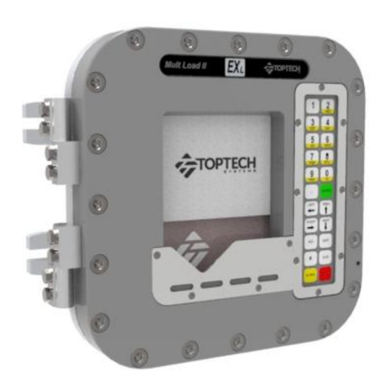
CHAPTER 2– OPERATING CONDITIONS AND COMPONENTS Chapter Chapter 2 Operating Conditions and Components Product Outline and Dimensions MultiLoad II/ RCU II – EXL Model - Picture Figure 2.1 MultiLoad II (ML II) / Remote Control Unit II (RCU II) Explosion Proof Lite (EXL) MultiLoad II/ RCU II Explosion Proof Lite (EXL) Installation Guide - Part # 6070... -
Page 15: Multiload Ii/ Rcu Ii - Exl Model - Dimensions
CHAPTER 2– OPERATING CONDITIONS AND COMPONENTS MultiLoad II/ RCU II – EXL Model – Dimensions The dimensions in this section are indicated in inches and millimeters (in parenthesis). 2.1.2.1 Front View Unit Outline Drawing – Front View Figure 2.2 2.1.2.2 Back View Unit Outline Drawing –... -
Page 16: 2.1.2.3 Bottom View
CHAPTER 2– OPERATING CONDITIONS AND COMPONENTS 2.1.2.3 Bottom View Unit Outline Drawing – Bottom View Figure 2.4 2.1.2.4 Side View Unit Outline Drawing – Side View Figure 2.5 MultiLoad II/ RCU II Explosion Proof Lite (EXL) Installation Guide - Part # 6070... -
Page 17: Operating Characteristics
CHAPTER 2– OPERATING CONDITIONS AND COMPONENTS Operating Characteristics The MultiLoad II/ RCU II – Explosion Proof Lite (EXL) Model has the following characteristics: Characteristics Description 85 - 250 Vac, 47-63 Hz, 300 – 150 mA Operating Voltage Voltage Option 9 - 30 Vdc, 600mA Operating Temperature 40°F to 140°F, -40°C to 60°C Enclosure... - Page 18 CHAPTER 2– OPERATING CONDITIONS AND COMPONENTS Internal I/O Heat Dissipation: I/O TYPE Voltage Freq Dissipation Digital/ Analog I/O 2 Meter I/O per Point # I/O TOTAL # I/O TOTAL Dissipation Dissipation [Hz] ACOUT 0.36 1.78 2.85 0.32 1.62 2.60 ACIN 0.73 1.46 0.44...
-
Page 19: Chapter 3 Installing The Multiload Ii/Rcuii Exl
CHAPTER 3– INSTALLING THE MULTILOAD II/RCUII EXL Chapter Chapter 3 Installing the MultiLoad II/RCUII EXL Tools Required Installation -8 mm hex wrench required for tightening cover bolts. Servicing and Repair #2 Philips screwdriver for circuit board removal. ¼” socket wrench for CPU circuit board removal and a 5/16” socket wrench for display board removal. -
Page 20: Cable Entries
Five M20x 1.5 mm cable entries are located at the bottom of the unit. Appropriate fasteners must be selected to support the minimum weight of 33 lbs. (15 kg). Toptech offers the following mounting suggestions for three typical surfaces: metal, wood, or concrete/solid block. -
Page 21: Figure 3.1 Suggested Mounting Position
CHAPTER 3– INSTALLING THE MULTILOAD II/RCUII EXL Figure 3.1 Suggested Mounting Position Figure 3.2 Screen Visible Area MultiLoad II/ RCU II Explosion Proof Lite (EXL) Installation Guide - Part # 6070... -
Page 22: Recommended Wire Sizes And Torque For All Terminal Blocks
CHAPTER 3– INSTALLING THE MULTILOAD II/RCUII EXL Recommended Wire Sizes and Torque for All Terminal Blocks Three sizes of terminal blocks are used in the MultiLoad II/ RCU II products: 7.62 mm pitch (supply power), 5.08 mm pitch (line voltage switching), and 3.81 mm pitch (serial communication, analog or dc voltages). -
Page 23: Ac Powered Models
CHAPTER 3– INSTALLING THE MULTILOAD II/RCUII EXL AC Powered Models Provide over current protection using a 15 Amp circuit breaker or equivalent. The breaker also serves as a means of disconnection from the operating supply as required by UL/ISA/IEC 61010-1 and CAN/CSA-C22.2 NO. -
Page 24: Dc Powered Models
CHAPTER 3– INSTALLING THE MULTILOAD II/RCUII EXL DC Powered Models The MultiLoad II/ and RCU II is optionally available with a 24 Vdc power supply. The power source used to supply the MutliLoad II/RCUII must be rated 9 – 30 Vdc SELV, Limited Energy (Class 2). The rated supply input current is 600mA. -
Page 25: Chapter 4 Data Communications Interface
CHAPTER 4– DATA COMMUNICATIONS INTERFACE Chapter Chapter 4 Data Communications Interface The MultiLoad II/ RCU II has four (4) communications ports (see Figure3.3), each with a specific purpose. The following section provides the information required to select and make the wiring connections to the ports: Communication Interface Type... -
Page 26: Rs-422/485
CHAPTER 4– DATA COMMUNICATIONS INTERFACE RS-422/485 The RS-422/485 communications protocol is designed for multi-point (i.e. computer to multiple devices, also called multi-dropped) communications up to 4,000 feet (1,220 Meters). RS-422 requires 4-wires (2 twisted pair) for full duplex communications and utilizes a transmit pair of wires (TDA &... -
Page 27: Ethernet
CHAPTER 4– DATA COMMUNICATIONS INTERFACE Ethernet The Ethernet controller on revision 2.0 CPU boards uses HP Auto-MDIX technology. By automatically detecting the signaling on the connected device, the transceiver will configure the port settings automatically. Thus, the choice of a straight through or cross over cable no longer has to be made—either will work. -
Page 28: Host/Tms Communications
CHAPTER 4– DATA COMMUNICATIONS INTERFACE Host/TMS Communications A host/ TMS computer system can be connected to the MultiLoad II/ RCU II in various ways : RS485 4-wire on COM 1 RS485 2-wire on COM1 RS232 on COM1 Ethernet on the ethernet port 4.2.2.1 COM 1 - RS-485 4-wire - Host/TMS Communications A host/ TMS computer system can be connected to the MultiLoad II/ RCU II via RS485 4-wire on... -
Page 29: 4.2.2.2 Com 1 - Rs-485 2-Wire: Host/Tms Communications
CHAPTER 4– DATA COMMUNICATIONS INTERFACE 4.2.2.2 COM 1 - RS-485 2-Wire: Host/TMS Communications The Host/TMS Computer System can be connected to the MultiLoad II/ RCU II via RS485 2-Wire on COM 1. The TD and RD pairs tied together at the Host/TMS and all MultiLoad II/ RCU IIs. Host/TMS MultiLoad II/ RS485... -
Page 30: 4.2.2.3 Com 1 - Rs-232 - Host/Tms Communications
CHAPTER 4– DATA COMMUNICATIONS INTERFACE 4.2.2.3 COM 1 - RS-232 - Host/TMS Communications The Host/TMS Computer System can be connected to the MultiLoad II/ RCU II via RS232 on COM The TX and RX are swapped at the Host/TMS. MultiLoad II/ Host/TMS RCU II COM 1 RS232... -
Page 31: 4.2.2.4 Ethernet - Host/Tms Communications
CHAPTER 4– DATA COMMUNICATIONS INTERFACE 4.2.2.4 Ethernet – Host/TMS Communications The Host/TMS Computer System can be connected to the MultiLoad II/ RCU II using Ethernet. The Ethernet controller on revision 2.0 CPU boards uses HP Auto-MDIX technology. By automatically detecting the signaling on the connected device, the transceiver will configure the port settings automatically. -
Page 32: 4.2.3.1 Com2 - Rs232 - Host Ticket Printer/Data Logger
CHAPTER 4– DATA COMMUNICATIONS INTERFACE 4.2.3.1 COM2 – RS232 - Host Ticket Printer/Data Logger A Ticket Printer or Data Logger can be connected to the MultiLoad II/ RCU II via RS232 on COM The TX and RX are swapped at the MultiLoad II/ RCU II. Handshake lines MUST be connected or terminated, or a printer error will be reported. -
Page 33: Figure 4.11 Ptb Printer Connection With Handshake
CHAPTER 4– DATA COMMUNICATIONS INTERFACE A Special variant of the ticket printing uses the PTB protocol. A PTB printer can be connected to the MultiLoad II/ RCU II via RS232 on COM 2 or COM1: MultiLoad II/ PTB Printer/ Logger RCU II COM 2 RS232 DB25 Connector 2 –... -
Page 34: Chapter 5 Connecting Field Devices To The I/O Board
CHAPTER 5– CONNECTING FIELD DEVICES TO THE I/O BOARD Chapter Chapter 5 Connecting Field Devices to the I/O Board Two I/O board options are offered for use with the MultiLoad II. They are the Digital/ Analog I/O Board and the 2 Meter I/O Board. They primarily differ in the number of I/O points, although the latter can control two meters as its name implies. -
Page 35: Available I/O Points Per Board
CHAPTER 5– CONNECTING FIELD DEVICES TO THE I/O BOARD Available I/O Points per Board The quantity and electrical ratings of the available I/O points per board are described in the table below. For easy recognition and use, a circuit symbol corresponding to its’ board is located in the last column: IGITAL ETER... - Page 36 CHAPTER 5– CONNECTING FIELD DEVICES TO THE I/O BOARD This list is not exhaustive, but contains those most frequently used: IRCUIT UNCTION YMBOL AC Output All AC outputs may be used as line voltage ON/ OFF control. AC Output If a digital valve control is used, PORT 2 is dedicated to control the (N.O.) upstream solenoid.
-
Page 37: Terminal Arrangements Per Board
CHAPTER 5– CONNECTING FIELD DEVICES TO THE I/O BOARD Terminal arrangements per Board Digital Analog I/O Board (IO_DA) IO_DA 100Ω PORT 0 °C °F PORT 1 4-20mA 4-20 mA IN PORT 2 12-30 Vdc (0 Vdc) 4-20 mA OUT PORT 3 4-20mA PORT 8 TB2A... -
Page 38: Meter I/O Board (Io-2M)
CHAPTER 5– CONNECTING FIELD DEVICES TO THE I/O BOARD 2 Meter I/O Board (IO-2M) IO_2M METER 0, PORT 0 100Ω METER 0, RTD °C METER 0, PORT 1 °F METER 0, PORT 2 METER 0, PORT 3 100Ω METER 1, RTD LINE °C °F... -
Page 39: How To Connect And Wire Field Devices To The I/O Boards
CHAPTER 5– CONNECTING FIELD DEVICES TO THE I/O BOARD How to Connect and Wire Field Devices to the I/O Boards In this section of the chapter we will provide examples of commonly used devices that can get wired to the I/O boards. This is not an exhaustive listing, but intended to provide you an example of how certain types of I/O need to get wired into the various boards. -
Page 40: Multiload Ii Flow Meter And Control Valve Wiring
CHAPTER 5– CONNECTING FIELD DEVICES TO THE I/O BOARD MultiLoad II Flow Meter and Control Valve Wiring I/O DIGITAL/ I/O 2 METER ANALOG METER 0 METER 1 IO_DA TB1 IO_2M TB3 IO_2M TB2 IN 10 PORT 0 OUT 5 PORT 0 OUT 5 PORT 3 PORT 0 PORT 3.IN/... -
Page 41: Multiload Ii Additive Wiring: Outputs
CHAPTER 5– CONNECTING FIELD DEVICES TO THE I/O BOARD MultiLoad II Additive Wiring: Outputs I/O DIGITAL/ I/O 2 METER ANALOG METER 0 METER 1 PORT 0 PORT 0.IN/ LINE.IN IO_DA TB1 IO_2M TB3 IO_2M TB2 ✓ ✓ ✓ PORT 0.OUT IN 10 PORT 0 OUT 5 PORT 0 OUT 5... -
Page 42: Multiload Ii Additive Wiring: Inputs
CHAPTER 5– CONNECTING FIELD DEVICES TO THE I/O BOARD MultiLoad II Additive Wiring: Inputs I/O DIGITAL/ I/O 2 METER 12Vdc ANALOG METER 0 METER 1 ~1 kΩ, 1/4W IO_DA TB2B IO_2M TB7 IO_2M TB8 PORT 4 ✓ ✓ ✓ PORT 4.+ PORT 4 PORT 4 PORT 4... -
Page 43: Multiload Ii Analog Wiring
CHAPTER 5– CONNECTING FIELD DEVICES TO THE I/O BOARD MultiLoad II Analog Wiring 5.4.4.1 RTD Wiring I/O DIGITAL/ I/O 2 METER ANALOG METER 0 METER 1 RTD.V+ 100 Ω IO_DA TB4 IO_2M TB4 IO_2M TB5 100Ω RTD.R+ ✓ ✓ ✓ °C RTD.R- ✓... -
Page 44: 5.4.4.2 Multiload Ii 4 - 20 Ma Input Wiring
CHAPTER 5– CONNECTING FIELD DEVICES TO THE I/O BOARD 5.4.4.2 MultiLoad II 4 – 20 mA Input Wiring 4-20 mA-IN I/O DIGITAL/ I/O 2 METER 4-20 mA 4-20mA 4-20 mA IN.I+ ANALOG METER 0 METER 1 4-20 mA IN.I- IO_DA TB6 †... -
Page 45: 5.4.4.3 Multiload Ii 4 - 20 Ma Output Wiring
CHAPTER 5– CONNECTING FIELD DEVICES TO THE I/O BOARD 5.4.4.3 MultiLoad II 4 – 20 mA Output Wiring IO_DA TB6 4-20 mA-OUT 4-20 mA 4-20mA 4-20 mA 4-20 mA OUT.I ✓ 4-20 mA OUT.GND ✓ 4-20 mA OUT.V+ COM 2 4-20 mA (0 Vdc) 12-30 Vdc... -
Page 46: Multiload Ii Ac Output Wiring
CHAPTER 5– CONNECTING FIELD DEVICES TO THE I/O BOARD MultiLoad II AC Output Wiring I/O DIGITAL/ I/O 2 METER ANALOG METER 0 METER 1 PORT 0 PORT 0.IN/ LINE.IN IO_DA TB1 IO_2M TB3 IO_2M TB2 PORT 0.OUT ✓ ✓ ✓ IN 10 PORT 0 OUT 5 PORT 0 OUT 5... -
Page 47: Multiload Ii Ac Input Wiring
CHAPTER 5– CONNECTING FIELD DEVICES TO THE I/O BOARD MultiLoad II AC Input Wiring I/O DIGITAL/ I/O 2 METER ANALOG METER 0 METER 1 PORT 8 IO_2M TB1 IO_2M TB1 PORT 8.L ✓ PORT PORT 8.N ✓ ✓ PORT ✓ PORT 8 PORT 8.L PORT 8.N... -
Page 48: Multiload Ii Dc Permissive/Status Wiring
CHAPTER 5– CONNECTING FIELD DEVICES TO THE I/O BOARD MultiLoad II DC Permissive/Status Wiring 5 – 30 Vdc I/O DIGITAL/ I/O 2 METER ANALOG METER 0 METER 1 IO_DA TB2B IO_2M TB7 IO_2M TB8 PORT 4 ✓ ✓ ✓ PORT 4.+ PORT 4 PORT 4 PORT 4... -
Page 49: Multiload Ii Dc Output Wiring
CHAPTER 5– CONNECTING FIELD DEVICES TO THE I/O BOARD MultiLoad II DC Output Wiring 5 – 30 Vdc I/O DIGITAL/ I/O 2 METER ANALOG METER 0 METER 1 IO_DA TB3 IO_2M TB9 IO_2M TB9 ✓ ✓ PORT PORT 10 ✓ ✓... -
Page 50: Multiload Ii 2 Output Air Eliminator Wiring
CHAPTER 5– CONNECTING FIELD DEVICES TO THE I/O BOARD MultiLoad II 2 Output Air Eliminator Wiring I/O DIGITAL/ I/O 2 METER ANALOG METER 0 METER 1 PORT 3.IN/ LINE.IN IO_DA TB1 IO_2M TB3 IO_2M TB2 PORT 3.OUT IN 10 PORT 0 OUT 5 PORT 0 OUT 5 PORT 0 OUT 9... -
Page 51: Multiload Ii Lectro Count Remote Display Wiring
CHAPTER 5– CONNECTING FIELD DEVICES TO THE I/O BOARD MultiLoad II Lectro Count Remote Display Wiring 5 – 28 Vdc I/O DIGITAL/ I/O 2 METER ANALOG METER 0 METER 1 ≥ 500 mA IO_DA TB3 IO_2M TB9 IO_2M TB9 ✓ ✓... -
Page 52: Rcu Ii Dc Input Wiring
CHAPTER 5– CONNECTING FIELD DEVICES TO THE I/O BOARD RCU II DC Input Wiring I/O DIGITAL/ I/O 2 METER ANALOG METER 0 METER 1 IO_DA TB2B IO_2M TB7 IO_2M TB8 ✓ ✓ ✓ PORT 4 PORT 4 PORT 4 ✓ ✓... -
Page 53: Rcu Ii Ac Output Wiring
CHAPTER 5– CONNECTING FIELD DEVICES TO THE I/O BOARD RCU II AC Output Wiring I/O DIGITAL/ I/O 2 METER ANALOG METER 0 METER 1 IO_DA TB1 IO_2M TB3 IO_2M TB2 ✓ ✓ ✓ IN 10 PORT 0 OUT 5 PORT 0 OUT 5 PORT 0 PORT 0 PORT 0.IN/... -
Page 54: Rcu Ii Dc Output Wiring
CHAPTER 5– CONNECTING FIELD DEVICES TO THE I/O BOARD RCU II DC Output Wiring 5 – 30 Vdc I/O DIGITAL/ I/O 2 METER ANALOG METER 0 METER 1 IO_DA TB3 IO_2M TB9 IO_2M TB9 ✓ ✓ PORT PORT 10/ PORT 10 ✓... -
Page 55: Typical 1 Meter Application Wiring Example: Ip&E Drawing (Electrical Wiring Schedule)
CHAPTER 5– CONNECTING FIELD DEVICES TO THE I/O BOARD Typical 1 Meter Application Wiring Example: IP&E Drawing (Electrical Wiring Schedule) MultiLoad II/ RCU II Explosion Proof Lite (EXL) Installation Guide - Part # 6070... -
Page 56: Chapter 6 Configurations
CHAPTER 6– CONFIGURATIONS Chapter Chapter 6 Configurations Switch Access Control The MultiLoad II contains switches which limit menu and configuration access. These switches limit users from accessing Program Mode, as well as from changing Weights and Measures controlled parameters. In Program Mode, the operator has access to the following: The Configuration Menu parameters. -
Page 57: Magnetic Bolts Program / W&M Switches (Current)
CHAPTER 6– CONFIGURATIONS Depending on the date of manufacture, the MultiLoad II may have one of three types of external switch design. All can be sealed and locked to prevent access to Program Mode and to prevent changes of Weights and Measures controlled parameters. 6.1.1.1 Magnetic Bolts Program / W&M Switches (current) This design is the most current and can be found on all new units. -
Page 58: Single Rotary Program / W&M Switch (Obsolete)
CHAPTER 6– CONFIGURATIONS 6.1.1.3 Single Rotary Program / W&M Switch (obsolete) This design consists of a single 3-position external rotary switch with two individual covers which may be locked and sealed with a wire and lead seal. The covers limit the switch rotation to three positions: A - Two covers closed: Program access is denied and Weights and Measures access is denied. -
Page 59: Internal Switch Access Control
CHAPTER 6– CONFIGURATIONS Internal Switch Access Control Two DIP switches on the CPU board also provide the closure of the program mode / W&M switch contacts. When the MultiLoad II/ RCU II does not have the external Program Mode / W&M switch installed, it is necessary to use these DIP switches on the CPU board to enable program mode and W&M access. -
Page 60: Menus And Screens
CHAPTER 6– CONFIGURATIONS Numeric keys (1 through 9 and 0) are used to enter numeric data. Alpha keys are used to enter text, and also to select/deselect alpha character entry. The CLR key is used to clear data entered in error; this is a backspace key erasing characters as the cursor moves backwards. -
Page 61: Field Modification And Data Entry
RCU Address: Card Reader: DISABLD Processing Mode Remote Swing Arn Secondary: DISABLD Terminal Name: Toptech Terminal Security Accounts Next Prev Exit Enter Press Enter to choose the field. A blinking cursor indicates that data can be entered. RCU GENERAL SETUP RCU Address: █... -
Page 62: Multiload Ii/ Rcu Ii Preliminary Configuration
123█ Card Reader: DISABLD Processing Mode: Remote Swing Arn Secondary: DISABLD Terminal Name: Toptech Terminal Security Accounts Next Prev Exit Enter Using this same screen as an example, the Processing Mode line is selected and Enter is pressed; use the Next or Prev keys to toggle between the values ENABLED and DISABLED, as shown below. You must then press Enter to accept the desired choice. - Page 63 CHAPTER 6– CONFIGURATIONS For Access Insert Driver Card Go to program mode by entering 00000 on the keypad, then press Next. A MultiLoad II must have the Program switch set to allow access to Program Mode (See section 6.1). 00000 is the factory default access code. See the “MultiLoad II User Guide,” RCU General Setup section for changing or adding new access codes.
- Page 64 Card Reader: DISABLD Card Reader: DISABLD Processing Mode: Remote Password: ***** Swing Arm Secondary: DISABLD Security: DISABLD Terminal Name: Toptech Terminal RCUOP Protocol: DISABLD Security Accounts Next Prev Exit Enter Next Prev Exit Enter Press Enter to save, then press Exit to return to the Configuration Menu.
-
Page 65: Verifying Communications Between Multiload Ii/ Rcu Ii And I/O Board
CHAPTER 6– CONFIGURATIONS Verifying Communications between MultiLoad II/ RCU II and I/O Board Enter program mode by pressing 00000 on the keypad, then press Next key. Select diagnostics from main menu: MultiLoad II RCU II D I A G N O S T I C S M E N U D I A G N O S T I C S M E N U... -
Page 66: Using I/O Diagnostics
CHAPTER 6– CONFIGURATIONS Using I/O Diagnostics MultiLoad II: Consult the MultiLoad II User Manual for diagnostics functions. RCU II: Each output is listed on the “RCU I/O Diagnostics” screen, adjacent to a [number]. Press the number on the keypad corresponding to the output under test. If the connection has been made properly, the field device will actuate. -
Page 67: Chapter 7 Service And Repair
CHAPTER 7– SERVICE AND REPAIR Chapter Chapter 7 Service and Repair Do not service MultiLoad II/ RCU II without disconnecting the supply circuit. Keep the enclosure tightly closed while circuits are live. Using a magnetic screwdriver is very helpful in retaining the screws during removal and installation. -
Page 68: Figure 7.2 Ml Ii/ Rcu Ii Exl Unit Assembly
CHAPTER 7– SERVICE AND REPAIR The MultiLoad II/ RCU II EXL has been constructed with replaceable modules or sub-assemblies that are available from Toptech. These include: CPU Subassembly (CPU Chassis, CPU Board, Power Supply/ COM Board, I/O Board) Display Subassembly (Active Matrix Display and Display Board) -
Page 69: Cpu Subassembly Removal And Replacement
CPU Subassembly Removal and Replacement The CPU subassembly exists out of the CPU chassis with the power supply/communications board and the CPU mounted. Optionally, an I/O board can be added to this subassembly. The CPU subassembly is comprised of different Toptech Parts. BOARD POWER... - Page 70 CHAPTER 7– SERVICE AND REPAIR Removal: 1. Disconnect all field wiring from the I/O board. 2. Disconnect all Serial Communications from the Power Supply/COM board. 3. Disconnect Main Power from the Power Supply/COM board. 4. Disconnect the flat display cable (after releasing the cam lock) and display power cable. 5.
-
Page 71: Display Subassembly Removal And Replacement
2. While supporting the display subassembly, remove the four mounting screws. 3. Do not attempt to disassemble the display subassembly. Return entire subassembly to Toptech for repair after receiving an RMA number. Installation: 1. While supporting the display subassembly, install the four mounting screws. -
Page 72: Flat Display Cable Connector: Remove And Connect
CHAPTER 7– SERVICE AND REPAIR Flat Display Cable Connector: Remove and Connect Part Number: Display Interface Cable: 1250 Removal: 1. To remove the display cable, rotate the cam to the open (up) position (see Figure 7.5). 2. Gently pull the cable straight out free of the connector. Installation: 1. -
Page 73: Keypad Removal And Replacement
CHAPTER 7– SERVICE AND REPAIR Keypad Removal and Replacement Part Number: EXL-Keypad: 1638 Removal: 1. Using a Torx T10 security screwdriver bit (available from McMaster Carr); remove all security screws holding on the Keypad bezel. 2. Remove the bezel. 3. Using a small flat screwdriver, carefully pry up the sealing gasket and keypad. They will both be removed together. -
Page 74: Keypad Barrier Removal And Replacement
CHAPTER 7– SERVICE AND REPAIR Keypad Barrier Removal and Replacement Part Number: EXL-Keypad Barrier: Version 1.1 - (obsolete) Version 2.0 – (current): 2710 The current keypad barrier (version 2.0) can be recognised by LED indicators. Barrier verson 1.1 is interchangeable with the current 2.0 version. Figure 7.10 Keyapd Barrier Version 2.0 (LED Figure 7.9... -
Page 75: Keypad Barrier Version 1.1 (No Led Indicators)
CHAPTER 7– SERVICE AND REPAIR Keypad Barrier Version 1.1 (no LED indicators) This barrier can be changed out by a version 2.0. Removal: 1. Disconnect the keypad cable from the display subassembly. 2. Remove the four screws holding barrier circuit box. 3. -
Page 76: Card Reader Removal And Replacement
CHAPTER 7– SERVICE AND REPAIR Card Reader Removal and Replacement Part Number: EXL Prox Card Reader 1669 Removal: 1. Disconnect the prox reader cable from the display subassembly. 2. Remove the two nuts holding prox reader. 3. Remove the prox reader. Installation: 1. -
Page 77: W&M Switch Assembly Removal And Replacement
W&M Assembly Board: 1900 W&M Bolt: 1901 This assembly is only found for MultiLoad II EXL devices. Removal: 1. Unplug the cable from the CPU board. Carefully depress the locking mechanism on the connector and gently pull. 2. Remove the two screws securing the switch board assembly. -
Page 78: Overview Parts List And Part Numbers
CHAPTER 7– SERVICE AND REPAIR Overview Parts List and Part Numbers The Toptech replacement part numbers are shown in the table below: Part Part Number Part Part Number EXL Display Assembly 1667 AC Power Supply Board : EXL Prox Card Reader 1669 Revision 1.0, 1.1... -
Page 79: Chapter 8 Hardware Revision History & Compatibility
CHAPTER 8– HARDWARE REVISION HISTORY & COMPATIBILITY Chapter Chapter 8 Hardware Revision History & Compatibility MultiLoad II/ RCU II Explosion Proof Lite (EXL) Installation Guide - Part # 6070... -
Page 80: Chapter 9 Revision History
CHAPTER 9– REVISION HISTORY Chapter Chapter 9 Revision History Hardware Revision Date Description 07/20/2008 Initial product release with ATEX certification. 12/19/2008 C/US UL Listing issued. 08/25/2009 Added display heater option. 08/25/2009 Alternate cast enclosure with alternate cement. 01/09/2009 Released magnetic switches for configuration & weights and measures. 03/25/2010 Changed regulatory agency from UL to CSA. -
Page 81: Manual Revision
CHAPTER 9– REVISION HISTORY Manual Revision Revision Date Description 1.0 (ML) 07/31/2007 Release. 1.1 (ML) 02/21/2008 Expanded I/O section to show FCM I and FCM II wiring connections; described FCM comm. wiring in chapter 4; reorganized serial comm description by function not port. 1.2 (ML) 04/18/2008 Removed FCM diagrams from chapter 4 and placed them in separate... -
Page 82: Multiload Ii/ Rcu Ii Explosion Proof Lite (Exl) Installation Guide - Part
CHAPTER 9– REVISION HISTORY 11/10/2017 Updated 60079-1 to the latest edition (2014). Removed expired old ATEX DOC. 12/27/2018 Manual update, formatting changes, restructuring, Updated Chapter 5 I/O wiring figures to support multilingual support, improved mechanical drawings, updated Declaration of Conformity, and included I/O heat dissipation, chapter 7 updated and completed. - Page 83 Toptech Systems North America office: Toptech Systems Inc 1124 Florida Central Parkway Longwood, FL 32750, USA Phone: +1 (407) 332-1774 Europe office: Toptech Systems NV Nieuwe Weg 1 2070 Zwijndrecht (Antwerp), Belgium Phone: +32 (0)3 250 60 60 MultiLoad II/ RCU II Explosion Proof Lite (EXL) Installation Guide - Part # 6070...
Need help?
Do you have a question about the MultiLoad II EXL and is the answer not in the manual?
Questions and answers