Table of Contents
Advertisement
Advertisement
Table of Contents

Subscribe to Our Youtube Channel
Related Manuals for Toptech MultiLoad II DIV-2


Summary of Contents for Toptech MultiLoad II DIV-2
- Page 1 MultiLoad II & RCU II DIVISION 2 (DIV2) Installation Guide (Part # 6074)
- Page 2 Toptech Systems, Inc. Disclaimer Toptech Systems assumes no responsibility for damages resulting from installation or use of its products. Toptech Systems will not be liable for any claims of damage, lost data, or lost time as a result of using its products.
- Page 3 EU Declaration of Conformity The signatory, representing the manufacturer, declares that the products listed below are in conformity with the essential requirements of the following EC Directive(s) when installed in accordance with the product installation instructions: 2014/32/EU The Measuring Instruments Directive (and its amending directives) 2014/30/EU The Electromagnetic Compatibility Directive (and its amending directives) 2014/34/EU...
-
Page 4: Table Of Contents
T able of Contents Overview ........................... 1 Chapter 1 General information & Warnings ............3 Receiving and/or Returning Equipment ............. 3 Safety Warnings ....................4 Electrostatic Discharge (ESD) Protection ............5 FCC Note ......................6 Chapter 2 Operating conditions and components ........... 7 Product Outline and dimensions ................ - Page 5 Chapter 4 Data Communications Interface ............20 Available Communications Protocol Selection and Wire spec ......21 4.1.1 RS-422/485 ....................21 4.1.2 RS-232 ..................... 21 4.1.3 Ethernet ....................22 Communication Connection Wiring ..............22 FCM I / FCM II Communications ( MultiLoad II Product Only) - COM 0 – 4.2.1 Port –...
- Page 6 5.4.13 RCU II DC Output Wiring ................ 49 5.4.14 Typical 1 meter application wiring example IP&E Drawing (electrical wiring schedule) ......................50 Chapter 6 Configurations ..................51 Switch Access Control ..................51 6.1.1 External Switch Access Control (MultiLoad II Only) ........51 6.1.2 External Type 1 Program / W&M switches ..........
- Page 7 Hardware Revision ..................80 Manual Revision ....................81...
- Page 8 T able of Figures MultiLoad II (ML II) / Remote Control Unit II (RCU II) Division 2 Unit .... 7 Figure 2.1 Unit Outline Drawing – Front View ............... 8 Figure 2.2 Unit Outline Drawing – Back View ............... 9 Figure 2.3 Unit Outline Drawing –...
- Page 9 Figure 7.2 ML II/ RCU II Div2 Unit Assembly Slotted Card Holder with MT11 ....66 Figure 7.3 CPU Board, Power Supply / Comm Board, I/O Board with Chassis .... 67 ML II/ RCU II Div2 Unit Cover Display Assembly ..........69 Figure 7.4 Figure 7-6 Cam lock in the closed (down) 70 Figure 7-5...
-
Page 10: Overview
Overview This document is designed to guide individuals installing MultiLoad II/ RCU II DIV2 equipment, engineering firms developing site electrical drawings, and users troubleshooting system operations such as managers, system administrators, technicians, and meter proving personnel. The following table provides an informative summary of the material available in this guide: Chapter Topics Covered 1.General... - Page 11 MultiLoad II User Guide. For information about wiring other models, please consult the respective installation guides. For information about the MultiLoad register interface and Modbus communication, please reference the MultiLoad II Communication Guide. Updated versions of all manuals, including this one, are available on our website at http://www.toptech.com.
-
Page 12: Chapter 1 General Information & Warnings
If any damage is visible, notify the carrier at once to establish liability. Contact Toptech’s Return Materials Department to initiate timely repair or replacement of the unit. A Return Materials Authorization (RMA) will be for the purpose of returning the product or parts requiring repair. -
Page 13: Safety Warnings
▲ A battery is soldered to the processor board for retention of data, time, and date. This battery should last more than ten years. Please return the board to Toptech Systems for battery replacement. This battery must be replaced with Matsushita Electric, model BR2477A only. -
Page 14: Electrostatic Discharge (Esd) Protection
▲ A battery is soldered to the processor board for retention of data, time, and date. This battery should last more than ten years. Please return the board to Toptech Systems for battery replacement. This battery must be replaced with Matsushita Electric, Model BR2477A only. -
Page 15: Fcc Note
FCC Note This equipment complies with the limits for a Class A Digital Device, pursuant to part 15 of the FCC Rules. These limits are designed to provide reasonable protection against harmful interference when the equipment is operated in a commercial environment. This equipment generates, uses, and can radiate radio frequency energy and, if not installed and used in accordance with the instruction manual, may cause harmful interference to radio communications. -
Page 16: Chapter 2 Operating Conditions And Components
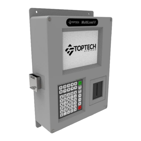
Chapter Chapter 2 Operating Conditions and Components Product Outline and dimensions 2.1.1 MultiLoad II/ RCU II – DIV2 Model - Picture Figure 2.1 MultiLoad II (ML II) / Remote Control Unit II (RCU II) Division 2 Unit... -
Page 17: Multiloadii/ Rcuii - Div2 Model - Dimensions
2.1.2 MultiLoad II/ RCU II – DIV2 Model – Dimensions The dimensions in this section are indicated in inches and millimeters (in parenthesis). 2.1.2.1 Front View Unit Outline Drawing – Front View Figure 2.2... -
Page 18: 2.1.2.2 Back View
2.1.2.2 Back View RCUII/ ML II Div 2 MOUNTING TEMPLATE Unit Outline Drawing – Back View Figure 2.3... -
Page 19: 2.1.2.3 Bottom View
2.1.2.3 Bottom View 2.1.2.3.1 2- Hole Base 2 x 1” NTP Aluminum HUBS Unit Outline Drawing – Bottom View -2 Hole Base Figure 2.4 2.1.2.3.2 5- Hole Base (Europe) 3xM20 and 2xM25 Unit Outline Drawing – Bottom View - 5 Hole Base Figure 2.5... -
Page 20: 2.1.2.4 Side View
2.1.2.4 Side View Unit Outline Drawing – Side View Figure 2.6... -
Page 21: Operating Characteristics
Operating Characteristics The Remote Control Unit – Division 2 (DIV2) Model has the following characteristics: Characteristics Description 85 - 250 Vac, 47-63 Hz, 300 – 150 mA Operating Voltage Voltage Option 9 - 30 Vdc, 600mA Operating Temperature 40°F to 140°F: -40°C to 60°C Enclosure Type 4, IP65 ETL Listed (US, Canada) Class 1, Division 2, Groups C &... - Page 22 Internal I/O Heat Dissipation: I/O TYPE Voltage Freq Dissipation Digital/ Analog I/O 2 Meter I/O per Point # I/O TOTAL # I/O TOTAL Dissipation Dissipation [Hz] ACOUT 0.36 1.78 2.85 0.32 1.62 2.60 ACIN 0.73 1.46 0.44 0.89 DCOUT 0.02 0.07 0.05 0.02...
-
Page 23: Chapter 3 Installing The Multiload Ii/Rcuii Div2
Chapter Chapter 3 Installing the MultiLoad II/RCUII DIV2 Tools Required 3.1.1 Installation ¼” Flat Head screw driver is required for tightening cover screws. 3.1.2 Servicing and Repair #2 Philips screwdriver for circuit board removal. ¼” socket wrench for CPU circuit board removal and a 5/16” socket wrench for display board removal. -
Page 24: Drywall
DIV-2 Mounting Template. The cable entries are located at the bottom of the unit. Appropriate fasteners must be selected to support the minimum weight of 24 lbs (11 kg). Toptech offers the following mounting suggestions for three typical surfaces: drywall, wood, or concrete/cinder block. -
Page 25: Figure 3.1 Suggested Mounting Position
Figure 3.1 Suggested Mounting Position Figure 3.2 Screen Visible Area... -
Page 26: Recommended Wire Sizes And Torque For All Terminal Blocks
Recommended Wire Sizes and Torque for All Terminal Blocks Three sizes of terminal blocks are used in the MultiLoad II/ RCU II products: 7.62 mm pitch (supply power), 5.08 mm pitch (line voltage switching), and 3.81 mm pitch (serial communication, analog or dc voltages). -
Page 27: Ac Powered Models
3.6.1 AC Powered Models Provide over current protection using a 15 Amp circuit breaker or equivalent. The breaker also serves as a means of disconnection from the operating supply as required by UL/ISA/IEC 61010-1 and CAN/CSA-C22.2 NO. 61010-1. The disconnected device may not be blocked or be made difficult to operate by the MultiLoad II/ RCU II or any other device. -
Page 28: Equipment Grounding
The 3-position terminal block is located in the right hand corner of the power supply/communication board. Wiring guidelines for using 24 Vdc power supply Wire gauge (AWG) Distance (feet) Figure 3.4 DC Power Connections 3.6.3 Equipment Grounding A safety ground should be attached to terminal block TB1 (on both ac and dc input power models) to maintain electrical safety in the event of a fault condition. -
Page 29: Chapter 4 Data Communications Interface
Chapter Chapter 4 Data Communications Interface The MultiLoad II/ RCU II has four (4) communications ports (see Figure3.3), each with a specific purpose. The following section provides the information required to select and make the wiring connections to the ports: Communication Interface Type Typical Function... -
Page 30: Available Communications Protocol Selection And Wire Spec
Available Communications Protocol Selection and Wire Spec This section describes the available communication protocols for MultiLoadII/RCU II. 4.1.1 RS-422/485 The RS-422/485 communications protocol is designed for multi-point (i.e. computer to multiple devices, also called multi-dropped) communications up to 4,000 feet (1,220 Meters). RS-422 requires 4-wires (2 twisted pair) for full duplex communications and utilizes a transmit pair of wires (TDA &... -
Page 31: Ethernet
30 pF maximum between conductors. 4.1.3 Ethernet The Ethernet controller on revision 2.0 CPU boards uses HP Auto-MDIX technology. By automatically detecting the signaling on the connected device, the transceiver will configure the port settings automatically. Thus, the choice of a straight through or cross over cable no longer has to be made—either will work. -
Page 32: Host/Tms Communications
MultiLoad II FCM / PCM FCM / PCM COM 0 Figure 4.1 FCM / PCM Connections 4.2.2 Host/TMS Communications A host/ TMS computer system can be connected to the MultiLoad II/ RCU II in various ways : RS485 4-wire on COM 1 RS485 2-wire on COM1 RS232 on COM1 Ethernet on the ethernet port... -
Page 33: 4.2.2.2 Com 1 - Rs-485 2-Wire: Host/Tms Communications
Figure 4.3 RS485 4-Wire, Host to Multiple MultiLoad II/ RCU IIs 4.2.2.2 COM 1 - RS-485 2-Wire: Host/TMS Communications The Host/TMS Computer System can be connected to the MultiLoad II/ RCU II via RS485 2-Wire on COM 1. The TD and RD pairs tied together at the Host/TMS and all MultiLoad II/ RCU IIs. Host/TMS MultiLoad II/ RS485... -
Page 34: 4.2.2.3 Com 1 - Rs-232 - Host/Tms Communications
MultILoad II / RCU II can be multridropped on the same communication line using RS485 – 2 Wire on COM 1: Host/TMS MultiLoad II/ MultiLoad II/ RCU RS485 RCU II #1 COM II #n COM 1 Figure 4.5 RS485 4-Wire, Host to Multiple MultiLoad II/ RCU IIs 4.2.2.3 COM 1 - RS-232 - Host/TMS Communications The Host/TMS Computer System can be connected to the MultiLoad II/ RCU II via RS232 on COM The TX and RX are swapped at the Host/TMS. -
Page 35: 4.2.2.4 Ethernet - Host/Tms Communications
MultiLoad II/RCUII has the ability to multi-drop onto a RS232 line on COM 1: Host/TMS MultiLoad II/ MultiLoad II/ RCU RS232 RCU II #1 COM II #n COM 1 Figure 4.7 RS232, Host to Multiple MultiLoad II/ RCU IIs 4.2.2.4 Ethernet – Host/TMS Communications The Host/TMS Computer System can be connected to the MultiLoad II/ RCU II using Ethernet. -
Page 36: Host Ticket Printer/Data Logger
4.2.3 Host Ticket Printer/Data Logger Ticket Printers or alibilog printers can be connected to the MultiLoad II/ RCU II in the following ways: RS 232 on COM1 RS 232 on COM2 Ethernet on the ethernet port 4.2.3.1 COM2 – RS232 - Host Ticket Printer/Data Logger A Ticket Printer or Data Logger can be connected to the MultiLoad II/ RCU II via RS232 on COM The TX and RX are swapped at the MultiLoad II/ RCU II. -
Page 37: Figure 4.10 Ticket Printer / Data Logger Connections Without Handshake
MultiLoad II/ Printer Logger RS232 RCU II COM 2 DB25 Connector 2 - TX 20 - DTR 3 - RX 7 – GND 4 – RTS 5 – CTS 6 – DSR 8 - DCD (N/C) DTR Figure 4.10 Ticket Printer / Data Logger Connections without Handshake When Print or Alibi Log is configured to be on COM 2, the CTS handshake line MUST be connected or a printer error will occur, preventing loading. - Page 38 COMMUNICATION SETUP COM (1) Baud Rate: 9600 Parity : Even Data Bits : 7 Data Stop Bits : 1 Stop Multidrop Single Type : Next Prev Exit Enter...
-
Page 39: Chapter 5 Connecting Field Devices To The I/O Board
Chapter Chapter 5 Connecting Field Devices to the I/O Board Two I/O board options are offered for use with the MultiLoad II. They are the Digital/ Analog I/O Board and the 2 Meter I/O Board. They primarily differ in the number of I/O points, although the latter can control two meters as its name implies. -
Page 40: Available I/O Points Per Board
Available I/O Points per Board The quantity and electrical ratings of the available I/O points per board are described in the table below. For easy recognition and use, a circuit symbol corresponding to its’ board is located in the last column: IGITAL ETER... - Page 41 Certain I/O circuit symbols have dedicated functions, which are described in the table below. This list is not exhaustive, but contains those most frequently used: IRCUIT UNCTION YMBOL AC Output All AC outputs may be used as line voltage ON/ OFF control. AC Output If a digital valve control is used, PORT 2 is dedicated to control the (N.O.) upstream solenoid.
-
Page 42: Terminal Arrangements Per Board
Terminal arrangements per Board 5.3.1 Digital Analog I/O Board (IO_DA) IO_DA 100Ω PORT 0 °C °F PORT 1 4-20mA 4-20 mA IN PORT 2 12-30 Vdc (0 Vdc) 4-20 mA OUT PORT 3 4-20mA PORT 8 TB2B TB2A 0° PORT 4 90°... -
Page 43: Meter I/O Board (Io-2M)
5.3.2 2 Meter I/O Board (IO-2M) IO_2M METER 0, PORT 0 100Ω METER 0, RTD °C METER 0, PORT 1 °F METER 0, PORT 2 METER 0, PORT 3 100Ω LINE METER 1, RTD °C °F METER 1, PORT 0 METER 1, PORT 1 12 Vdc METER 1, PORT 2... -
Page 44: How To Connect And Wire Field Devices To The I/O Boards
How to Connect and Wire Field Devices to the I/O Boards In this section of the chapter we will provide examples of commonly used devices that can get wired to the I/O boards. This is not an exhaustive listing, but intended to provide you an example of how certain types of I/O need to get wired into the various boards. -
Page 45: Multiload Ii Flow Meter And Control Valve Wiring
5.4.1 MultiLoad II Flow Meter and Control Valve Wiring I/O DIGITAL/ I/O 2 METER ANALOG METER 0 METER 1 IO_DA TB1 IO_2M TB3 IO_2M TB2 IN 10 PORT 0 OUT 5 PORT 0 OUT 5 PORT 3 PORT 0 PORT 3.IN/ OUT 9 PORT 1 OUT 4 PORT 1 OUT 4... -
Page 46: Multiload Ii Additive Wiring: Outputs
5.4.2 MultiLoad II Additive Wiring: Outputs I/O DIGITAL/ I/O 2 METER ANALOG METER 0 METER 1 PORT 0 PORT 0.IN/ LINE.IN IO_DA TB1 IO_2M TB3 IO_2M TB2 PORT 0.OUT IN 10 PORT 0 OUT 5 PORT 0 OUT 5 PORT 0 ... -
Page 47: Multiload Ii Additive Wiring: Inputs
5.4.3 MultiLoad II Additive Wiring: Inputs I/O DIGITAL/ I/O 2 METER 12Vdc ANALOG METER 0 METER 1 ~1 kΩ, 1/4W IO_DA TB2B IO_2M TB7 IO_2M TB8 PORT 4 PORT 4.+ PORT 4 PORT 4 PORT 4 ... -
Page 48: Multiload Ii Analog Wiring
5.4.4 MultiLoad II Analog Wiring 5.4.4.1 RTD Wiring I/O DIGITAL/ I/O 2 METER ANALOG METER 0 METER 1 RTD.V+ 100 Ω IO_DA TB4 IO_2M TB4 IO_2M TB5 100Ω RTD.R+ °C RTD.R- °F RTD.COM α=0.00385 ... -
Page 49: 5.4.4.2 Multiload Ii 4 - 20 Ma Wiring
5.4.4.2 MultiLoad II 4 – 20 mA Wiring I/O DIGITAL/ I/O 2 METER ANALOG METER 0 METER 1 4-20 mA-IN 4-20 mA IO_DA TB6 4-20mA 4-20 mA IN.I+ 4-20 mA 4-20 mA IN.I- COM 2 4-20 mA IOUT 3 N/A 4 4-20 mA-IN 4-20 mA... -
Page 50: Multiload Ii Ac Output Wiring
5.4.5 MultiLoad II AC Output Wiring I/O DIGITAL/ I/O 2 METER ANALOG METER 0 METER 1 PORT 0 PORT 0.IN/ LINE.IN IO_DA TB1 IO_2M TB3 IO_2M TB2 PORT 0.OUT IN 10 PORT 0 OUT 5 PORT 0 OUT 5 PORT 0 ... -
Page 51: Multiload Ii Ac Input Wiring
5.4.6 MultiLoad II AC Input Wiring I/O DIGITAL/ I/O 2 METER ANALOG METER 0 METER 1 PORT 8 IO_2M TB1 IO_2M TB1 PORT 8.L PORT PORT 8.N PORT PORT 8 PORT 8.L PORT 8.N PORT 8 PORT 8.L PORT 8.N Note: This shows a typical configuration. -
Page 52: Multiload Ii Dc Permissive/Status Wiring
5.4.7 MultiLoad II DC Permissive/Status Wiring 5 – 30 Vdc I/O DIGITAL/ I/O 2 METER ANALOG METER 0 METER 1 IO_DA TB2B IO_2M TB7 IO_2M TB8 PORT 4 PORT 4.+ PORT 4 PORT 4 PORT 4 ... -
Page 53: Multiload Ii Dc Output Wiring
5.4.8 MultiLoad II DC Output Wiring 5 – 30 Vdc I/O DIGITAL/ I/O 2 METER ANALOG METER 0 METER 1 IO_DA TB3 IO_2M TB9 IO_2M TB9 PORT PORT 10 0.10 OUT 2 OUT 2 OUT 2 ... -
Page 54: Multiload Ii 2 Output Air Eliminator Wiring
5.4.9 MultiLoad II 2 Output Air Eliminator Wiring I/O DIGITAL/ I/O 2 METER ANALOG METER 0 METER 1 PORT 3.IN/ LINE.IN IO_DA TB1 IO_2M TB3 IO_2M TB2 PORT 3.OUT IN 10 PORT 0 OUT 5 PORT 0 OUT 5 PORT 0 OUT 9 PORT 1 OUT 4 PORT 1 OUT 4... -
Page 55: Multiload Ii Lectro Count Remote Display Wiring
5.4.10 MultiLoad II Lectro Count Remote Display Wiring 5 – 28 Vdc I/O DIGITAL/ I/O 2 METER ANALOG METER 0 METER 1 ≥ 500 mA IO_DA TB3 IO_2M TB9 IO_2M TB9 PORT PORT 10 0.10 OUT 2 OUT 2 OUT 2 ... -
Page 56: Rcu Ii Dc Input Wiring
5.4.11 RCU II DC Input Wiring I/O DIGITAL/ I/O 2 METER ANALOG METER 0 METER 1 IO_DA TB2B IO_2M TB7 IO_2M TB8 PORT 4 PORT 4 PORT 4 12 Vdc PORT 5 PORT 5 PORT 5 PORT 4 PORT 4.+... -
Page 57: Rcu Ii Ac Output Wiring
5.4.12 RCU II AC Output Wiring I/O DIGITAL/ I/O 2 METER ANALOG METER 0 METER 1 IO_DA TB1 IO_2M TB3 IO_2M TB2 IN 10 PORT 0 OUT 5 PORT 0 OUT 5 PORT 0 PORT 0 PORT 0.IN/ ... -
Page 58: Rcu Ii Dc Output Wiring
5.4.13 RCU II DC Output Wiring 5 – 30 Vdc I/O DIGITAL/ I/O 2 METER ANALOG METER 0 METER 1 IO_DA TB3 IO_2M TB9 IO_2M TB9 PORT PORT 10/ PORT 10 0.10 OUT 2 OUT 2 OUT 2 PORT 0.10 ... -
Page 59: Typical 1 Meter Application Wiring Example Ip&E Drawing (Electrical Wiring Schedule)
5.4.14 Typical 1 Meter Application Wiring Example: IP&E Drawing (Electrical Wiring Schedule) -
Page 60: Chapter 6 Configurations
Chapter Chapter 6 Configurations Switch Access Control The MultiLoad II contains switches which limit menu and configuration access. These switches limit users from accessing Program Mode, as well as from changing Weights and Measures controlled parameters. In Program Mode, the operator has access to the following: The Configuration Menu parameters. -
Page 61: External Type 1 Program / W&M Switches
Depending on the date of manufacture, the MultiLoad II may have one of three types of external switch design. All can be sealed and locked to prevent access to Program Mode and to prevent changes of Weights and Measures controlled parameters. 6.1.2 External Type 1 Program / W&M Switches This design consists of two separate external rotary switches: one for Program Mode Access, and one... - Page 62 B - First cover open: Program access allowed and Weights and Measures access denied. C - Both covers open: Program access allowed and Weights and Measures access allowed.
-
Page 63: External Type 3 Program / W&M Switches
6.1.4 External Type 3 Program / W&M Switches The third design consists of two separate external magnetic bolts, one for program mode access, and one for W&M change access. Program or W&M access is achieved by removing the corresponding bolt. Each bolt has a small hole that can be sealed with a wire and lead seal to detect unauthorized access. -
Page 65: Multiload Ii/ Rcu Ii Div-2 Keypad
Figure 6.4 CPU DIP Switches for Program and W&M Access (rev 1.0) Figure 6.5 CPU DIP Switches for Program and W&M Access (rev 2.0) Field Switch Access Control (MultiLoad II Only) The MultiLoad II also has the ability to accept field inputs for the program mode and W&M access switches. -
Page 66: Menus And Screens
Numeric keys (1 through 9 and 0) are used to enter numeric data. Alpha keys are used to enter text, and also to select/deselect alpha character entry. The CLR key is used to clear data entered in error; this is a backspace key erasing characters as the cursor moves backwards. Menus and Screens The MultiLoad II Main Menu is shown below. -
Page 67: Field Modification And Data Entry
RCU Address: Card Reader: DISABLD Processing Mode Remote Swing Arn Secondary: DISABLD Terminal Name: Toptech Terminal Security Accounts Next Prev Exit Enter Press ENTER to choose the field. A blinking cursor indicates that data can be entered. RCU GENERAL SETUP RCU Address: █... -
Page 68: Multiload Ii/ Rcu Ii Preliminary Configuration
123█ Card Reader: DISABLD Processing Mode: Remote Swing Arn Secondary: DISABLD Terminal Name: Toptech Terminal Security Accounts Next Prev Exit Enter Using this same screen as an example, the Processing Mode line is selected and ENTER is pressed; use the NEXT or PREV keys to toggle between the values ENABLED and DISABLED, as shown below. - Page 69 For Access Insert Driver Card Go to program mode by entering 00000 on the keypad, then press Next. A MultiLoad II must have the Program switch set to allow access to Program Mode (See section 6.1). 00000 is the factory default access code. See the “MultiLoad II User Guide,” RCU General Setup section for changing or adding new access codes.
- Page 70 RCU Address: Card Reader: DISABLD Card Reader: Slot CAPTIVE Processing Mode: Remote Password: ***** Swing Arm Secondary: DISABLD Security: DISABLED Terminal Name: Toptech Terminal RCUOP Protocol Security Accounts Next Prev Exit Enter Next Prev Exit Enter MultiLoad II RCU II...
-
Page 71: Verify Communications Between Multiload Ii/ Rcu Ii And I/O Board
Press Exit to return to the Configuration Menu. Select and press Enter to return to the Main Menu. If the MultiLoad II/ RCU II has a Program/Weights and Measures switch, return the switch to Operating Mode. Verifying Communications between MultiLoad II/ RCU II and I/O Board Enter program mode by pressing 00000 on the keypad, then press Next key. -
Page 72: Using I/O Diagnostics
If 00-ERR (or “I/O Board Com: ERR”) appears, verify the communication parameters for Com0 within the Communication Setup Menu. This menu is located under the Configuration Menu. The Com0 communication settings required for the I/O board are .57.6 (K Baud), None (Parity), 8 Data (bits), 1 Stop (bit), Single, and I/O Board (type of serial device). -
Page 74: Chapter 7 Service And Repair
Chapter Chapter 7 Service and Repair Do not service MultiLoad II/ RCU II without disconnecting the supply circuit. Keep the enclosure tightly closed while circuits are live. Using a magnetic screwdriver is very helpful in retaining the screws during removal and installation. -
Page 75: Figure 7.2 Ml Ii/ Rcu Ii Div2 Unit Assembly Slotted Card Holder With Mt11
The MultiLoad II/ RCU II DIV-2 has been constructed with replaceable modules or sub-assemblies that are available from Toptech. These include: CPU Subassembly (CPU Chassis, CPU Board, Power Supply/ COM Board, I/O Board) Display Subassembly (Active Matrix Display and Display Board) -
Page 76: Cpu Subassembly Removal And Replacement
CPU Subassembly Removal and Replacement The CPU subassembly exists out of the CPU chassis with the power supply/communications board and the CPU mounted. Optionally, an I/O board can be added to this subassembly. The CPU subassembly is comprised of different Toptech Parts. BOARD POWER... - Page 77 Removal: 1. Disconnect all field wiring from the I/O board. 2. Disconnect all Serial Communications from the Power Supply/COM board. 3. Disconnect Main Power from the Power Supply/COM board. 4. Disconnect the flat display cable (after releasing the cam lock) and display power cable. 5.
-
Page 78: Display Subassembly Removal And Replacement
2. While supporting the display subassembly, remove the four mounting screws. 3. Do not attempt to disassemble the display subassembly. Return entire subassembly to Toptech for repair after receiving an RMA number. Installation: 1. While supporting the display subassembly, install the four mounting screws. -
Page 79: Keypad Removal And Replacement
Removal: 1. To remove the display cable, rotate the cam to the open (up) position (see Figure 7.5). 2. Gently pull the cable straight out free of the connector. Installation: 1. To install the display cable, make sure the cam is in the open (up) position. 2. -
Page 80: Card Reader Removal And Replacement
Removal: 1. Disconnect the keypad cable from the back of the keypad. 2. Using a #2 screwdriver, remove all screws holding on the keypad plate. 3. Remove the plate. 4. Using a flat screwdriver, carefully pry out the keypad. Installation: 1. -
Page 81: Bracket Mounted (Obsolete) Prox Reader Removal And Replacement
Part Number: 4726 Removal: 1. Disconnect the prox reader cable from the display subassembly. 2. Remove the 4 screws from the card holder back. 3. Remove the screw at the top of the card reader. 4. Lift the card reader off the card reader backplate. It is not necessary to remove the card reader back plate. -
Page 82: Slotted Card Holder Mounted Prox Reader Hid (Obsolete) Removal And Replacement
3. Remove the prox reader. Installation with Older Part: 1. Reinstall the prox reader with the two nuts. 2. Connect the prox reader cable to the display subassembly. Figure 7.10 ML II/ RCU II Div2 Cover Assembly Prox Bracket Mount Thinline II (Obsolete) 7.5.3 Slotted Card Holder Mounted Prox Reader HID (Obsolete) Removal and Replacement: Replacement part number: 4726... -
Page 83: Slotted Card Holder Mounted Twic Reader (Obsolete) Removal And Replacement
2. Reinstall the screws and lockwasher. 3. Connect the prox reader cable to the display subassembly. PROX READER Figure 7.11 ML II/ RCU II Div2 Cover with Slotted Card Holder Thinline II (Obsolete) 7.5.4 Slotted Card Holder Mounted TWIC Reader (Obsolete) Removal and Replacement: Replacement part number: 4726 Removal: 1. -
Page 84: W&M Switch Assembly Removal And Replacement
3. Connect the prox reader cable to the display subassembly. Figure 7.12 ML II/ RCU II Div2 Unit Assembly Prox/TWIC Slotted Card Holder RP15 (Obsolete) W&M Switch Assembly Removal and Replacement Part Number: W&M Assembly Board: 1900 W&M Bolt: 1901 This assembly is only found for MultiLoad II DIV2 devices. -
Page 85: Ice Shield Removal And Replacement
Installation: 1. Install the new switch assembly using the same screws. Install with the cut corners facing outward. DO NOT over-tighten and simply secure gently. Over-tightening will crack the ferrite rings, damaging the switch. 2. Reinstall the connector. 3. Installation complete. Figure 7.13 ML II/ RCU II DIV2 W&M Assembly Ice Shield Removal and Replacement... -
Page 86: Overview Parts List And Partnumbers
3. Replace the four screws holding the prox ring and tighten using the T10 torx bit. ICE SHIELD PROX RING Figure 7.14 Ice Shield Assembly Installation Slotted Card Holder Overview Parts List and Part Numbers The Toptech replacement part numbers are shown in the table below: Part Part Number Part Part Number... - Page 87 Display Interface Cable 1250 Revision 1.1 4729 Backlight power cable 2224 Ice Shield 2443 I/O Board : Digital/ Analog I/O, revision 1.1 4718 2 Meter I/O Board, revision 1.0 4723 CPU Board : Revision 1.0 obsolete Revision 2.0 4727...
-
Page 88: Chapter 8 Hardware Revision History & Compatibilty
Chapter Chapter 8 Hardware Revision History & Compatibility... -
Page 89: Chapter 9 Revision History
Chapter Chapter 9 Revision History Hardware Revision Date Description 09/08/2006 Initial product release with C/US UL Listing. 12/19/2008 Added display heater option. 06/12/2007 Moved board mounting chassis to the upper left of enclosure, from upper center. 07/09/2007 Replaced Samsung SRAM with Cypress. 08/20/2007 New firmware released for I/O board because of PIC18F die revision. - Page 90 02/08/2011 Released 2 Meter I/O board option (IO_2M rev 1.0). 02/08/2011 Capacitive keypad option released (RCUII_DIVII_SOLID_STATE_KP rev 1.0). 03/08/2011 Changed regulatory agency from CSA to Intertek. 01/17/2012 Replaced relay assemblies on I/O board with discrete triacs (IO_DA rev 1.2, IO_2M rev 1.1).
- Page 91 1.3 (ML) 07/25/2008 Added FCM I and II simulator description. 1.4 (ML) 12/19/2008 Added instructions required by update from UL508 to UL61010-1 that customer is required to use a Class 2 power source when using the DC power supply; described wiring partitions; described three types of PGM W&M switches: shaft and magnetic bolts;...
- Page 92 12/20/2018 Updated Chapter 5 I/O wiring figures to support multilingual support, improved mechanical drawings, updated Declaration of Conformity, and included I/O heat dissipation.
- Page 93 Toptech Systems North America office: Toptech Systems Inc 1124 Florida Central Parkway Longwood, FL 32750, USA Phone: +1 (407) 332-1774 Europe office: Toptech Systems NV Nieuwe Weg 1 2070 Zwijndrecht (Antwerp), Belgium Phone: +32 (0)3 250 60 60...
Need help?
Do you have a question about the MultiLoad II DIV-2 and is the answer not in the manual?
Questions and answers