Table of Contents
Advertisement
Advertisement
Table of Contents

Related Manuals for Toptech FCM II


Summary of Contents for Toptech FCM II
- Page 1 FCM II (Flow Control Module) Installation Guide Part # 2307 April 26, 2013...
- Page 2 IEC 61010-1: 2004 Electrical Equipment for Measurement, Control, and Laboratory Use; Part 1: General Requirements Year of CE Marking: 2007 Name: William J. Porthouse Position: Director of Engineering & Production Date: 19-April-2016 FCM II Installation Guide: 20160419 - Part # 2307...
-
Page 3: Electrical Considerations And Regulatory Requirements
LECTRICAL ONSIDERATIONS AND EGULATORY EQUIREMENTS Equipment Operation. If the equipment is used in a manner not specified in this installation guide, the protection provided by the equipment may be impaired.. This equipment is suitable for use in Class I, Division 2, Groups C and D hazardous locations OR non-hazardous locations only. - Page 4 Toptech Systems, Inc. Disclaimer Toptech Systems assumes no responsibility for damages resulting from installation or use of its products. Toptech Systems will not be liable for any claims of damage, lost data, or lost time as a result of using its products.
-
Page 5: Table Of Contents
Generic I/O Simulation .......................... 35 CHAPTER 5 Troubleshooting ........................36 Is The Module Powered?........................36 Is The Module Communicating? ......................36 Are The Inputs Functioning? ........................ 37 Are The Outputs Functioning? ......................37 FCM II Installation Guide: 20160419 - Part # 2307... - Page 6 Power and Communication Distribution ....................45 6.3.2 Wiring Terminal Identification ......................47 6.3.3 Voltage Distribution ..........................48 CHAPTER 7 Hardware Revision History ....................... 49 CHAPTER 8 Manual Revision History ......................50 FCM II Installation Guide: 20160419 - Part # 2307...
- Page 7 FCM II Power and Serial Communication Panel Wiring: Single Row ........45 Figure 6.8 FCM II Power and Serial Communication Panel Wiring: Two Rows, Two Serial Ports ..46 Figure 6.9 FCM II Power and Serial Communication Panel Wiring: Two Rows, One Serial Port .... 47 Figure 6.10...
-
Page 8: Chapter 1 General
FCM II is available in six varieties (see Figures 1.1 and 1.2 below). This modular construction simplifies the process of FCM mapping to field devices by appropriating each FCM II model with just the right amount of I/O for its designated purpose. In addition, FCM IIs are DIN rail (35mm) mountable and require no wiring between units;... -
Page 9: Electrical Ratings
100mA Max Limited Energy FCM II DC OUT Min. 19 Vdc 30 Vdc Max. 36 Vdc 250mA max. 100mA Max 6K Cycles, Pilot Duty Figure 1.2 FCM II Module Electrical Ratings FCM II Installation Guide: 20160419 - Part # 2307... -
Page 10: Operating Conditions
ISCHARGE ROTECTION The FCM II contains electronic components and assemblies subject to damage by ESD. The FCM II was designed to protect against ESD while the unit is mounted on an electrical panel and in normal operation. Proper handling procedures must be observed during the removal, installation, repair and other handling of FCM II modules summarized below. -
Page 11: Chapter 2 Installation
NSTALLATION FCM II modules are easily attached to 35mm DIN rails by tilting the top edge toward the panel and catching the top edge on the rail (see Figure 2.1 below). Then the module is swung back down until the spring loaded metal foot catches on the bottom edge of the rail (see Figure 2.2 below). -
Page 12: Fcm Ii Panels And Enclosures
AYOUTS Toptech Systems assembles standard panel layouts which are shown in Chapter 6. These include a 20 inch by 20 inch panel with a single DIN rail of FCM IIs or a 30 inch by 30 inch panel with two DIN rails of FCM IIs. -
Page 13: Electrical Supply Connections
Although the ten position power/communication bus terminal block is rated for solid or stranded copper wire 14 to 30 AWG [2.1 to 0.05 mm ], Toptech recommends using stranded 16 to 18 AWG [1.3 to 0.8 mm ] for power. See section 2.5 regarding the choice of communication wire. -
Page 14: Serial Communication Connection
Maximum length: 4,000 feet (1,220 Meters) Maximum stub length: 15 feet. All exposed shields must be properly insulated to prevent short circuits. All shields must be continuous, soldered and properly insulated. FCM II Installation Guide: 20160419 - Part # 2307... -
Page 15: Device Address Configuration
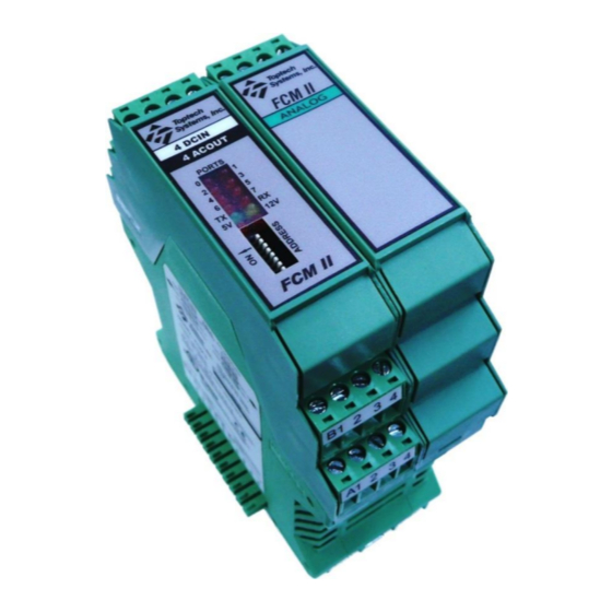
Port 5 Status Port 6 Status Port 7 Status TX Status RX Status FCM 5V Power FCM 12V Output FCM Address Dip Switches Figure 2.5 Module Status, Configuration Setting and Identification FCM II Installation Guide: 20160419 - Part # 2307... -
Page 16: Swing Arms
To achieve this, the FCM II controlling the I/O associated with that field equipment must have its communication switched between the MutliLoad II on each lane, depending on which lane the load arm resides when in use. -
Page 17: Figure 2.7 Swing Arm Wiring Of Shared Fcm Iis
Figure 2.7 Swing Arm Wiring of Shared FCM IIs FCM II Installation Guide: 20160419 - Part # 2307... -
Page 18: Chapter 3 Field Wiring
AWG [3.3 to 0.05 mm ], Toptech recommends using stranded copper wire 12 AWG to 24 AWG [3.3 to 0.2 mm depending on the type of field device. The required screw tightening torque is 5 to 7 Lb-in. [0.6 to 0.8 Nm]. Wires must be stripped ¼”... -
Page 19: Terminal Identification
FCM II Single And Double Module Comparison 3.2.1 ERMINAL DENTIFICATION All DC Field Wiring Connections Power/COM Connection Bus Power/COM Connection Bus All AC Field Wiring Connections Figure 3.2 FCM II Field Wiring Terminal Locations FCM II Installation Guide: 20160419 - Part # 2307... -
Page 20: Flow Meter And Control Valve Wiring
Port 3 Bottom Side Middle Row Port 0 Port 1 Bottom Side Bottom Row Terminal Number Figure 3.3 FCM II Field Wiring: Flow Meter and Control Valve FCM II Installation Guide: 20160419 - Part # 2307... -
Page 21: Additive Wiring
Port 0 Output Valve Port 0 Port 1 Bottom Side Solenoid Bottom Row Terminal Number Figure 3.4 FCM II Field Wiring: Additive Meters and Injection Valves FCM II Installation Guide: 20160419 - Part # 2307... -
Page 22: Rtd Temperature Probe Wiring
Note: All 4 wires MUST be run to the sensor. Do not simply jumper REF- to COM or REF+ to V+ at the FCM II. For 3-wire and 2 wire probes, the connection of REF- to COM and REF+ to V+ should be as close as possible to the probe (within inches). -
Page 23: 4-20Ma Input Wiring: Loop Current Provided By External Power Supply
NOTE: The receiver does not contain a voltage source. The loop must be powered either by the transmitter or by an external power supply. The I/O Board adds 75 Ohms to the loop. FCM II Installation Guide: 20160419 - Part # 2307... -
Page 24: 4-20Ma Input Wiring: Loop Current Provided By Transmitter
NOTE: The receiver does not contain a voltage source. The loop must be powered either by the transmitter or by an external power supply. The I/O Board adds 75 Ohms to the loop. FCM II Installation Guide: 20160419 - Part # 2307... -
Page 25: 4-20Maoutput Wiring
Note: The 4-20mA output requires a power source (12-30vdc). The 12vdc output can be used as shown here. 4-20mA Receiver Figure 3.8 FCM II Field Wiring: 4-20mA Output FCM II Installation Guide: 20160419 - Part # 2307... -
Page 26: Ac Permissive/Status Wiring (6Acin)
AC inputs. Middle Row Port 0 Port 1 Bottom Side Bottom Row Figure 3.9 FCM II Field Wiring: AC Permissive/Status (6ACIN) FCM II Installation Guide: 20160419 - Part # 2307... -
Page 27: Ac Output Wiring (6Acout)
Bottom Side Middle Row Port 0 Port 1 Bottom Side Bottom Row Figure 3.10 FCM II Field Wiring: AC Pump and Valve Control (6ACOUT) FCM II Installation Guide: 20160419 - Part # 2307... -
Page 28: Dc Permissive/Status Wiring (6Dcin)
Status Port 5 Input Etc. Note: This shows a typical configuration. DC Permissive/Status inputs can be assigned to any unused DC inputs. Figure 3.11 FCM II Field Wiring: DC Permissive/Status (6DCIN) FCM II Installation Guide: 20160419 - Part # 2307... -
Page 29: Dc Permissive/Status Wiring (4Dcin/4Acout)
Bottom Side Bottom Row Note: Ports 4-7 can be used for general DC inputs when not configured for additive or component meter input. Figure 3.12 FCM II Field Wiring: DC Input (4DCIN/4ACOUT) FCM II Installation Guide: 20160419 - Part # 2307... -
Page 30: Ac Output Wiring (4Dcin/4Acout)
AC ouputs can be assigned to any unused AC outputs. Port 0 Port 1 Bottom Side Bottom Row Terminal Number Figure 3.13 FCM II Field Wiring: AC Output (4DCIN/4ACOUT) FCM II Installation Guide: 20160419 - Part # 2307... -
Page 31: Dc Output Wiring (6Dcout)
Note: This shows a typical configuration. DC ouputs can be assigned to any unused DC outputs. Any DC output port can be configured as an output pulse Figure 3.14 FCM II Field Wiring: DC Output (6DCOUT) FCM II Installation Guide: 20160419 - Part # 2307... -
Page 32: Output Air Eliminator Wiring
Note 2: Port 1 configured as Alt. High Flow Rate Inversed. When this signal is removed, the flow rate will drop to the Alt. High Flow Rate. Figure 3.15 FCM II Field Wiring: 3 Output Air Eliminator FCM II Installation Guide: 20160419 - Part # 2307... -
Page 33: Output Air Eliminator Wiring
Note 2: With only two states returned from the air eliminator, flow must be completely stopped to purge air. To purge air by only slowing the rate, a 3 output air eliminator head must be used. Figure 3.16 FCM II Field Wiring: 2 Output Air Eliminator FCM II Installation Guide: 20160419 - Part # 2307... -
Page 34: Lectro Count Remote Display Wiring
Counter Increment Pulses (White) (Batch Authorized Inverse Port) Counter Reset Pulse (Green) External Power Supply Note: 1. Use only model E1613. Figure 3.17 FCM II Field Wiring: Lectro Count Remote Display FCM II Installation Guide: 20160419 - Part # 2307... -
Page 35: Chapter 4 Simulation
IMULATION The FCM II simulator is a special version of an FCM II 4DCIN, 4ACOUT module. The FCM II simulator differs from an FCM 1 simulator in that it is configured entirely from MultiLoad (no keyboard or display required). This simulator is able to perform most all of the FCM I simulator functions with the exception of forcing error conditions and looping back outputs to inputs. -
Page 36: Chapter 5 Troubleshooting
OWERED All standalone FCM II modules have a front panel LED that shows the power status of its 5V power. In addition, the 4DCIN/4ACOUT module has a 12V indicator LED showing the status of its onboard 12 Vdc supply used to power field device dc inputs. -
Page 37: Are The Inputs Functioning
4) If screen display is the same as above, the FCM IIs are communicating with the MultiLoad II. 5) If an FCM II is not communicating, the message XX-ERR appears where XX is the address of the FCM that is not communicating. -
Page 38: Are Rtd Errors Present
Please consult the MultiLoad User Manual for further errors that are not covered here. The MultiLoad User Manual describes in great detail how to configure an FCM II panel for most kinds of control applications as well as how to troubleshoot those setups. -
Page 39: Chapter 6 Dimensions, Panel Layouts, Wiring Suggestions
Chapter 6 – Dimensions, Panel Layouts, Wiring CHAPTER 6 IMENSIONS ANEL AYOUTS IRING UGGESTIONS ODULE IMENSIONS Figure 6.1 FCM II Single Module Dimensions FCM II Installation Guide: 20160419 - Part # 2307... -
Page 40: Figure 6.2 Fcm Ii Double Module Dimensions
Chapter 6 – Dimensions, Panel Layouts, Wiring Figure 6.2 FCM II Double Module Dimensions FCM II Installation Guide: 20160419 - Part # 2307... -
Page 41: Standard Panel Dimensions
The maximum number of FCM IIs on this panel is the equivalent of 12 single wide modules. Toptech recommends mounting the power supply on the DIN rail with the FCM IIs as most DIN rail power supplies require vertical mounting and top/bottom clearance for proper cooling. -
Page 42: Figure 6.4 20 Inch X 20 Inch Enclosure Dimensions
Chapter 6 – Dimensions, Panel Layouts, Wiring Figure 6.4 20 Inch x 20 Inch Enclosure Dimensions FCM II Installation Guide: 20160419 - Part # 2307... -
Page 43: Inch X 30 Inch Panel
The maximum number of FCM IIs on this panel is the equivalent of 18 single wide modules per row (36 total). Toptech recommends mounting the power supply on the DIN rail with the FCM IIs as most DIN rail power supplies require vertical mounting and top/bottom clearance for proper cooling. ... -
Page 44: Figure 6.6 30 Inch X 30 Inch Enclosure Dimensions
Chapter 6 – Dimensions, Panel Layouts, Wiring Figure 6.6 30 Inch x 30 Inch Enclosure Dimensions FCM II Installation Guide: 20160419 - Part # 2307... -
Page 45: Panel Electrical Wiring Suggestions
OMMUNICATION ISTRIBUTION FCM II modules were designed to minimize 24 Vdc input power and serial communication wiring by employing a distribution buss in the base of the modules. Therefore, considerations only have to be made as to which side of a DIN rail assembly the power and communication cable should attach (left side female plug or right side male plug). -
Page 46: Figure 6.8 Fcm Ii Power And Serial Communication Panel Wiring: Two Rows, Two Serial Ports
Chapter 6 – Dimensions, Panel Layouts, Wiring Figure 6.8 FCM II Power and Serial Communication Panel Wiring: Two Rows, Two Serial Ports FCM II Installation Guide: 20160419 - Part # 2307... -
Page 47: Wiring Terminal Identification
Chapter 6 – Dimensions, Panel Layouts, Wiring Figure 6.9 FCM II Power and Serial Communication Panel Wiring: Two Rows, One Serial Port 6.3.2 IRING ERMINAL DENTIFICATION Figure 6.10 shows the terminal block labeling of field connections. All modules follow the convention of labeling bottom side plugs from A to C as the staircase to the top and D to F for the top side plugs as they staircase to the top. -
Page 48: Voltage Distribution
Ground/Overfill output required by digital control valves. Note: Do not use FCM II ac outputs to directly run pumps. Use an interposing relay. The rated currents of the ac output modules should be sufficient for most types of solenoid valves but note the ratings as shown in Figure 1.2 and section 3.2. -
Page 49: Chapter 7 Hardware Revision History
Approved alternate bottom terminal block. 05/11/2012 Replaced AC relay assemblies with discrete triacs (4IN/4OUT, 6ACOUT). 05/11/2012 Replaced DC relay assemblies with discrete MOSFETs (6DCOUT). 10/01/2014 Improved RTD filtering (IO_DA rev 1.3, IO_2M rev 1.2) FCM II Installation Guide: 20160419 - Part # 2307... -
Page 50: Chapter 8 Manual Revision History
Added LectroCount wiring 04/26/2013 Dropped revision number control; control by release date 04/26/2013 Added 12Vdc supply load rating 04/26/2013 Updated European DOC 04/19/2016 Revised Declaration of Conformity (new directive dates in effect 4/20/2016) FCM II Installation Guide: 20160419 - Part # 2307...
Need help?
Do you have a question about the FCM II and is the answer not in the manual?
Questions and answers