Siemens SINAMICS S120 Manual
Hide thumbs
Also See for SINAMICS S120:
- Function manual (1094 pages) ,
- Diagnostic manual (947 pages) ,
- Manual (848 pages)
Table of Contents
Advertisement
Quick Links
Advertisement
Table of Contents

Related Manuals for Siemens SINAMICS S120


Summary of Contents for Siemens SINAMICS S120
- Page 3 ___________________ AC Drive Foreword Fundamental safety ___________________ instructions ___________________ SINAMICS System overview Mains connection and line- ___________________ side power components S120 AC Drive ___________________ Power Modules ___________________ DC link components Manual ___________________ Motor-side power components ___________ Control Units, Control Unit Adapters and operating components ___________...
- Page 4 Note the following: WARNING Siemens products may only be used for the applications described in the catalog and in the relevant technical documentation. If products and components from other manufacturers are used, these must be recommended or approved by Siemens. Proper transport, storage, installation, assembly, commissioning, operation and maintenance are required to ensure that the products operate safely and without any problems.
-
Page 5: Foreword
Siemens' content, and adapt it for your own machine documentation. Training At the following address (http://www.siemens.com/sitrain), you can find information about SITRAIN (Siemens training on products, systems and solutions for automation and drives). FAQs You can find Frequently Asked Questions in the Service&Support pages under Product Support (https://support.industry.siemens.com/cs/de/en/ps/faq). - Page 6 SINUMERIK 840D sl Type 1B • Equipment for Machine Tools (Catalog NC 62) Installation/assembly SINAMICS S120 Manual for Control Units and Additional System Components • SINAMICS S120 Manual for Booksize Power Units • SINAMICS S120 Manual for Booksize Power Units C/D Type •...
- Page 7 Foreword Usage phase Document/tool Maintenance/servicing SINAMICS S120 Commissioning Manual with STARTER • SINAMICS S120/S150 List Manual • SINAMICS S120 Commissioning Manual with Startdrive • References SINAMICS S120/S150 List Manual • available as of Startdrive V14 release Target group This documentation is intended for machine manufacturers, commissioning engineers, and service personnel who use the SINAMICS drive system.
- Page 8 Relevant directives and standards You can obtain an up-to-date list of currently certified components on request from your local Siemens office. If you have any questions relating to certifications that have not yet been completed, please ask your Siemens contact person.
-
Page 9: Ac Drive Manual, (Gh6), 07/2016, 6Sl3097-4Al00-0Bp5
SINAMICS S devices showing the test symbols fulfil the EMC requirements for Australia and New Zealand. Quality systems Siemens AG employs a quality management system that meets the requirements of ISO 9001 and ISO 14001. Not relevant standards China Compulsory Certification SINAMICS S devices do not fall in the area of validity of the China Compulsory Certification (CCC). - Page 10 This document contains recommendations relating to third-party products. Siemens accepts the fundamental suitability of these third-party products. You can use equivalent products from other manufacturers. Siemens does not accept any warranty for the properties of third-party products. AC Drive Manual, (GH6), 07/2016, 6SL3097-4AL00-0BP5...
- Page 11 Foreword Ground symbols Table 2 Symbols Symbol Meaning Connection for protective conductor (PE) Ground (e.g. M 24 V) Connection for function potential bonding Testing the protection against electric shock when using frequency converters Protection on indirect contact in the motor circuit of a converter and automatic disconnection in case of a fault in accordance with DIN EN 60364-4-4 VDE 0100, part 410 is ensured if the following conditions are met: ●...
- Page 12 Foreword AC Drive Manual, (GH6), 07/2016, 6SL3097-4AL00-0BP5...
-
Page 13: Table Of Contents
Residual risks of power drive systems ..................27 System overview ........................... 29 Field of application ........................29 Platform Concept and Totally Integrated Automation ............. 30 Overview, SINAMICS S120 AC Drive ..................32 SINAMICS S120 components ....................33 System data ..........................34 2.5.1 System data for PM240-2 Blocksize Power Modules ............. - Page 14 Table of contents 3.7.6.1 Technical data, Blocksize line filter ..................65 3.7.6.2 Technical data, Chassis line filter ..................66 Line reactors .......................... 67 3.8.1 Description ..........................67 3.8.2 Safety instructions for line reactors ..................67 3.8.3 Dimension drawings ....................... 69 3.8.4 Mounting ..........................
- Page 15 Table of contents 4.3.2.5 X42 terminal strip ........................145 4.3.2.6 X46 Brake control and monitoring ..................145 4.3.2.7 DRIVE-CLiQ interface X400-X402 ..................146 4.3.2.8 Meaning of the LEDs on the Power Module ................. 147 4.3.3 Connection example ......................148 4.3.4 Dimension drawings ......................
- Page 16 Table of contents 6.2.1.2 Safety instructions for motor reactors .................. 193 6.2.1.3 Dimension drawing ......................195 6.2.1.4 Technical data ........................196 6.2.2 Sinusoidal filter ........................196 6.2.2.1 Description ........................... 196 6.2.2.2 Safety instructions for sine-wave filters ................197 6.2.2.3 Dimension drawing ......................199 6.2.2.4 Technical data ........................
- Page 17 Table of contents 7.3.4.2 Behavior of the LEDs during booting ..................241 7.3.4.3 Behavior of the LEDs in the operating state ................. 242 7.3.5 Dimension drawing ....................... 244 7.3.6 Technical data ........................245 Control Unit CU310-2 DP (PROFIBUS)................245 7.4.1 Description ..........................
- Page 18 Table of contents 7.6.4 Meaning of the LEDs ......................281 7.6.5 Dimension drawing ......................282 7.6.6 Technical data ........................282 Mounting Control Units and Control Unit Adapters .............. 283 Basic Operator Panel BOP20 ....................284 7.8.1 Description ........................... 284 7.8.2 Interface description ......................
- Page 19 Table of contents 8.3.3.1 Overview ..........................330 8.3.3.2 X11 interface to the Control Interface Module ..............331 8.3.3.3 X12 230 V AC power supply ....................331 8.3.3.4 X14 load connection ......................331 8.3.3.5 X15 fast de-energization ....................... 332 8.3.4 Connection example ......................332 8.3.5 Dimension drawing .......................
- Page 20 Table of contents 10.6.1.3 DRIVE-CLiQ signal cables MOTION-CONNECT with DRIVE-CLiQ connectors ....362 10.6.1.4 MOTION-CONNECT DRIVE-CLiQ signal cables with DRIVE-CLiQ connector and M12 socket ........................... 363 10.6.1.5 Comparison of DRIVE-CLiQ signal cables ................364 10.6.1.6 Combined use of MOTION-CONNECT 500 and MOTION-CONNECT 800PLUS ....366 10.6.2 Power cables for motors ......................
-
Page 21: Fundamental Safety Instructions
Fundamental safety instructions General safety instructions DANGER Danger to life due to live parts and other energy sources Death or serious injury can result when live parts are touched. • Only work on electrical devices when you are qualified for this job. •... - Page 22 Fundamental safety instructions 1.1 General safety instructions WARNING Danger to life when live parts are touched on damaged devices Improper handling of devices can cause damage. For damaged devices, hazardous voltages can be present at the enclosure or at exposed components;...
- Page 23 Fundamental safety instructions 1.1 General safety instructions WARNING Danger to life due to fire spreading if housing is inadequate Fire and smoke development can cause severe personal injury or material damage. • Install devices without a protective housing in a metal control cabinet (or protect the device by another equivalent measure) in such a way that contact with fire is prevented.
- Page 24 Fundamental safety instructions 1.1 General safety instructions WARNING Danger of an accident occurring due to missing or illegible warning labels Missing or illegible warning labels can result in accidents involving death or serious injury. • Check that the warning labels are complete based on the documentation. •...
-
Page 25: Safety Instructions For Electromagnetic Fields (Emf)
Fundamental safety instructions 1.2 Safety instructions for electromagnetic fields (EMF) Safety instructions for electromagnetic fields (EMF) WARNING Danger to life from electromagnetic fields Electromagnetic fields (EMF) are generated by the operation of electrical power equipment such as transformers, converters or motors. People with pacemakers or implants are at a special risk in the immediate vicinity of these devices/systems. -
Page 26: Industrial Security
Siemens recommends strongly that you regularly check for product updates. For the secure operation of Siemens products and solutions, it is necessary to take suitable preventive action (e.g. cell protection concept) and integrate each component into a holistic, state-of-the-art industrial security concept. -
Page 27: Residual Risks Of Power Drive Systems
Fundamental safety instructions 1.5 Residual risks of power drive systems Residual risks of power drive systems When assessing the machine- or system-related risk in accordance with the respective local regulations (e.g., EC Machinery Directive), the machine manufacturer or system installer must take into account the following residual risks emanating from the control and drive components of a drive system: 1. - Page 28 Fundamental safety instructions 1.5 Residual risks of power drive systems AC Drive Manual, (GH6), 07/2016, 6SL3097-4AL00-0BP5...
-
Page 29: System Overview
System overview Field of application SINAMICS is the family of drives from Siemens designed for machine and plant engineering applications. SINAMICS offers solutions for all drive tasks: ● Simple pump and fan applications in the process industry. ● Complex single drives in centrifuges, presses, extruders, elevators, as well as conveyor and transport systems ●... -
Page 30: Platform Concept And Totally Integrated Automation
Communication via PROFINET This Ethernet-based bus enables control data to be exchanged at high speed via PROFINET IO with IRT or RT and makes SINAMICS S120 a suitable choice for integration in high-performance multi-axis applications. At the same time, PROFINET also uses standard IT mechanisms (TCP/IP) to transport information, e.g. - Page 31 System overview 2.2 Platform Concept and Totally Integrated Automation Figure 2-2 SINAMICS as part of the Siemens modular automation system AC Drive Manual, (GH6), 07/2016, 6SL3097-4AL00-0BP5...
-
Page 32: Overview, Sinamics S120 Ac Drive
System overview 2.3 Overview, SINAMICS S120 AC Drive Overview, SINAMICS S120 AC Drive SINAMICS S120 AC Drive is a modular drive system for individual axes and addresses sophisticated drive tasks for an extremely wide range of industrial applications. Applications include: ●... -
Page 33: Sinamics S120 Components
System overview 2.4 SINAMICS S120 components SINAMICS S120 components Figure 2-3 SINAMICS S120 component overview AC Drive Manual, (GH6), 07/2016, 6SL3097-4AL00-0BP5... -
Page 34: System Data
● Power Modules (either with or without integrated line filter) and an integrated braking chopper to provide power to the connected motor To address the required functions, SINAMICS S120 AC Drive is equipped with: ● Control Units that provide the drive and technological functions ●... - Page 35 System overview 2.5 System data Line power factor for line supply voltage 3 AC and type rating Devices FSA to FSC Active power factor (cos φ1): > 0.96 Power factor (λ): > 0.70 ... 0.85 Devices FSD to FSF Active power factor (cos φ1): > 0.98 ... 0.99 Power factor (λ): >...
- Page 36 System overview 2.5 System data Table 2- 2 Degree of protection / protection class Degree of protection IPXXB according to EN 60529, open type according to UL/CSA Protection class, line supply circuits I, with protective conductor connection Electronic circuits extra-low-voltage PELV/SELV Shock protection According to EN 50274 / BGV A3 when used for the intended purpose Cooling method...
- Page 37 System overview 2.5 System data Installation altitude Operation with low overload 0 ... 1000 m above sea level without derating Operation with high overload 0 ... 2000 m above sea level without derating > 2000 ... 4000 m above sea level Reduction of the ambient temperature by 3.5 K per 500 m •...
-
Page 38: Safety Data For Power Modules, Chassis Format
1.1 ... 447 kW: 65 kA to UL508C (up to 600 V) UL certification applies only in conjunction with the fuses prescribed by Siemens and not with other types or circuit breakers alone. Overvoltage category III to EN 61800-5-1 Degree of pollution 2 according to EN 61800-5-1 100 % output voltage only possible with modulation type "edge modulation"... - Page 39 System overview 2.5 System data Operation Class 3K3 according to EN 60721-3-3 Temperature: 0 ... +40 °C without derating > 40 ... +55 °C with reduction of the output current by 2.67 % pro °C Relative humidity: 5 ... 90 % no condensation Oil mist, salt mist, ice formation, condensation, dripping water, spraying water, splashing water and water jets are not permitted Mechanical environmental conditions...
-
Page 40: Derating
System overview 2.6 Derating Derating Derating as a function of the ambient temperature and installation altitude You can find data regarding derating as a function of the ambient temperature and installation altitude in Chapter System data (Page 34); a distinction is made between blocksize and chassis (built-in) devices. - Page 41 System overview 2.6 Derating Derating as a function of the output frequency Power Modules blocksize format (FSA to FSC) If the Power Modules are operated at an output frequency < 22 Hz, then you must reduce the output currents I and I as follows: Figure 2-6...
- Page 42 System overview 2.6 Derating AC Drive Manual, (GH6), 07/2016, 6SL3097-4AL00-0BP5...
-
Page 43: Mains Connection And Line-Side Power Components
Mains connection and line-side power components Introduction The following line-side components should be used to connect a SINAMICS drive line-up to the supply network: ● Line disconnector ● Overcurrent protection device (line fuses or circuit-breaker) ● Line contactor (this is required for electrical isolation) ●... -
Page 44: Information On The Disconnector Unit
Mains connection and line-side power components 3.2 Information on the disconnector unit Figure 3-1 Example of a Blocksize line connection (FSA to FSC) Figure 3-2 Example of a chassis line connection Information on the disconnector unit A line disconnector is required for disconnecting the drive line-up from the supply system. This must be selected in compliance with local regulations. -
Page 45: Overcurrent Protection By Means Of Line Fuses And Circuit Breakers
Mains connection and line-side power components 3.3 Overcurrent protection by means of line fuses and circuit breakers Overcurrent protection by means of line fuses and circuit breakers 3.3.1 Power Modules, blocksize format You must use line fuses or circuit-breakers for cable protection/overcurrent protection. The types in the following tables can be used. - Page 46 Mains connection and line-side power components 3.3 Overcurrent protection by means of line fuses and circuit breakers Table 3- 2 Fuses for PM240-2 FSB Power Modules, line voltage 1 AC / 3 AC 200 … 240 V Article No. 6SL3210- 6SL3210- 6SL3210- 6SL3211-...
-
Page 47: Line Fuses For Power Modules Blocksize Format 400 V
Mains connection and line-side power components 3.3 Overcurrent protection by means of line fuses and circuit breakers Table 3- 5 Fuses for PM240-2 FSE Power Modules, line voltage 3 AC 200 … 240 V Article number 6SL3210- 6SL3210- 1PC28-0UL0 1PC31-1UL0 without integrated line filter Fuses UL Class J AJT100... - Page 48 Mains connection and line-side power components 3.3 Overcurrent protection by means of line fuses and circuit breakers Table 3- 8 Fuses for PM240-2 FSA Power Modules (2/2), line voltage 3 AC 380 … 480 V Article number 6SL3210- 6SL3210- 6SL3211- 1PE16-1UL1 1PE18-0UL1 1PE18-0UL1...
- Page 49 Mains connection and line-side power components 3.3 Overcurrent protection by means of line fuses and circuit breakers Table 3- 11 Fuses for PM240-2 FSD Power Modules, line voltage 3 AC 380 … 480 V Article number 6SL3210- 6SL3210- 6SL3210- 6SL3210- 1PE23-8UL0 1PE24-5UL0 1PE26-0UL0...
-
Page 50: Line Fuses For Power Modules Blocksize Format 690 V
Mains connection and line-side power components 3.3 Overcurrent protection by means of line fuses and circuit breakers Table 3- 13 Fuses for PM240-2 FSF Power Modules, line voltage 3 AC 380 … 480 V Article number 6SL3210- 6SL3210- 6SL3211- 6SL3211- 1PE31-5UL0 1PE31-8UL0 1PE32-1UL0... - Page 51 Mains connection and line-side power components 3.3 Overcurrent protection by means of line fuses and circuit breakers Table 3- 15 Fuses for PM240-2 FSD Power Modules (2/2), line voltage 3 AC 500 … 690 V Article number 6SL3210- 6SL3210- 1PH23-5UL0 1PH24-2UL0 Without integrated line filter 1PH23-5AL0...
-
Page 52: Power Modules Chassis Format
Mains connection and line-side power components 3.3 Overcurrent protection by means of line fuses and circuit breakers Table 3- 17 Fuses for PM240-2 FSF Power Modules, line voltage 3 AC 500 … 690 V Article number 6SL3210- 6SL3210- 6SL3210- 6SL3210- 1PH28-0UL0 1PH31-0UL0 1PH31-2UL0... -
Page 53: Using Residual-Current Devices
Mains connection and line-side power components 3.4 Using residual-current devices Using residual-current devices Selectively tripping, AC/DC-sensitive residual current devices (type B) can be used in addition to the overcurrent protection devices. Residual current devices have to be installed if the power supply conditions in terms of short- circuit power and loop impedance at the infeed point are not such that the installed overcurrent protection devices will trip within the prescribed period if a fault occurs. -
Page 54: Surge Voltage Protection
Mains connection and line-side power components 3.5 Surge voltage protection Conditions when using differential current monitoring devices ● Use only AC/DC-sensitive RCM type B devices with delayed tripping that guarantee reliable tripping even for smoothed DC residual currents. ● Connect parts of the power drive system and the machine that can be touched to the PE conductor of the plant. -
Page 55: Line Filter
Category C1 (cable conducted): ● FSA to FSC: line filters from Siemens that can be base mounted ● FSD to FSF: You can obtain information about line filters through our "Siemens Product Partners for Drive Options (https://w3.siemens.com/mcms/mc-... -
Page 56: Safety Instructions For Line Filters
Mains connection and line-side power components 3.7 Line filter 3.7.2 Safety instructions for line filters WARNING Danger to life if the fundamental safety instructions and residual risks are not heeded Failure to heed the fundamental safety instructions and residual risks in Chapter 1 can result in accidents causing severe injuries or death. - Page 57 Damage of further loads due to incorrect line filters Unsuitable line filters can cause line harmonics, which damage or destroy loads connected to the same line supply. • Only use line filters released by Siemens for SINAMICS. AC Drive Manual, (GH6), 07/2016, 6SL3097-4AL00-0BP5...
-
Page 58: Electromagnetic Compatibility (Emc) Of The System
Mains connection and line-side power components 3.7 Line filter 3.7.3 Electromagnetic compatibility (EMC) of the system An explanation of the EMC environment and EMC Categories is provided in Chapter "Classification of EMC behavior (Page 352)". Category C2 Under the following conditions, the Power Modules comply with the limit values of category ●... -
Page 59: Dimension Drawings
Mains connection and line-side power components 3.7 Line filter 3.7.4 Dimension drawings Blocksize line filter Figure 3-3 Dimension drawing of the line filter, Power Module PM240-2 frame size FSA, all data in mm (inches) AC Drive Manual, (GH6), 07/2016, 6SL3097-4AL00-0BP5... - Page 60 Mains connection and line-side power components 3.7 Line filter Figure 3-4 Dimension drawing of the line filter, Power Module PM240-2 frame size FSB, all data in mm (inches) AC Drive Manual, (GH6), 07/2016, 6SL3097-4AL00-0BP5...
- Page 61 Mains connection and line-side power components 3.7 Line filter Figure 3-5 Dimension drawing of the line filter, Power Module PM240-2 frame size FSC, all data in mm (inches) AC Drive Manual, (GH6), 07/2016, 6SL3097-4AL00-0BP5...
- Page 62 Mains connection and line-side power components 3.7 Line filter Chassis line filter Figure 3-6 Dimension drawing, line filter AC Drive Manual, (GH6), 07/2016, 6SL3097-4AL00-0BP5...
- Page 63 Mains connection and line-side power components 3.7 Line filter Table 3- 19 Dimensions of the line filter, all data in mm and (inches) 6SL3000- 0BE32-5AA0 0BE34-4AA0 0BE36-0AA0 360 (14.17) 360 (14.17) 400 (15.74) 240 (9.44) 240 (9.44) 265 (10.43) 116 (4.56) 116 (4.56) 140 (5.51) 40 (1.57)
-
Page 64: Mounting
Mains connection and line-side power components 3.7 Line filter 3.7.5 Mounting External line filters for Power Modules in the blocksize format are designed as base components. The line filter is retained on the mounting surface and the Power Module is mounted on the line filter in a space-saving fashion. -
Page 65: Technical Data
Mains connection and line-side power components 3.7 Line filter 3.7.6 Technical data 3.7.6.1 Technical data, Blocksize line filter Table 3- 22 Technical data of line filter Blocksize PM240-2 Line voltage 3-phase 380 ... 480 VAC Line filter 6SL3203- 0BE17-7BA0 0BE21-8BA0 0BE23-8BA0 Frame size Suitable for Power... -
Page 66: Technical Data, Chassis Line Filter
Mains connection and line-side power components 3.7 Line filter 3.7.6.2 Technical data, Chassis line filter Table 3- 23 Technical data, Chassis line filter Order number 6SL3000- 0BE32-5AA0 0BE34-4AA0 0BE34-4AA0 0BE34-4AA0 0BE36-0AA0 Suitable for 6SL3310- 1TE32-1AA. 1TE32-6AA. 1TE33-1AA. 1TE33-8AA. 1TE35-0AA. Power Module Unit rating of the Power Module Rated voltage... -
Page 67: Line Reactors
Mains connection and line-side power components 3.8 Line reactors Line reactors 3.8.1 Description The line reactors limit low-frequency line harmonics and reduce the load on the rectifiers in the Power Modules. They are used to smooth voltage spikes (line supply faults) or to bridge voltage dips/interruptions when commutating. - Page 68 Damage to the system due to impermissible line reactors An impermissible line reactor may cause damage to the system and any further loads operated on the same power network. • Only use line reactors that SIEMENS has released for SINAMICS. NOTICE Line reactor damage due to interchanged connections Interchanging the input and output connections will damage the line reactor.
-
Page 69: Dimension Drawings
Mains connection and line-side power components 3.8 Line reactors 3.8.3 Dimension drawings Figure 3-8 Dimensional drawing of line reactors, PM240-2 frame size FSA, 0.55 … 1.1 kW, all dimensions in mm and (inch) Figure 3-9 Dimensional drawing of line reactors, PM240-2 frame size FSA, 1.5 … 4.0 kW, all dimensions in mm and (inch) Figure 3-10 Dimensional drawing of line reactors, PM240-2, frame size FSB, 4.0 …... - Page 70 Mains connection and line-side power components 3.8 Line reactors Figure 3-11 Dimensional drawing of line reactors, PM240-2, frame size FSC, 11 … 15 kW, all dimensions in mm and (inch) Chassis line reactors ① Mounting hole Figure 3-12 Dimension drawing, line reactors Table 3- 24 Dimensions of the line reactors, all data in mm (inches) 6SL3000-...
-
Page 71: Mounting
Mains connection and line-side power components 3.8 Line reactors 6SL3000- 0CE32-3AA0 0CE32-8AA0 0CE33-3AA0 0CE35-1AA0 hmax 248 (9.76) 248 (9.76) 248 (9.76) 269 (10.59) 150 (5.90) 150 (5.90) 150 (5.90) 180 (7.08) 60 (2.36) 60 (2.36) 60 (2.36) 60 (2.36) 101 (3.97) 101 (3.97) 101 (3.97) 118 (4.64) -
Page 72: Electrical Connection
Mains connection and line-side power components 3.8 Line reactors 3.8.5 Electrical Connection Line/load connection ① Line reactor ② Power Module Figure 3-13 Power Module with line filter ① Line reactor ② Line filter ③ Power Module Figure 3-14 Power Module with line reactor and line filter AC Drive Manual, (GH6), 07/2016, 6SL3097-4AL00-0BP5... -
Page 73: Technical Data
Mains connection and line-side power components 3.8 Line reactors 3.8.6 Technical data 3.8.6.1 Blocksize line reactors Table 3- 26 Technical data for PM240-2 line reactors Article No. 6SL3203- 0CE13-2AA0 0CE21-0AA0 0CE21-8AA0 0CE23-8AA0 Frame size Matching Power Line voltage 1-phase 200 VAC -10% to 240 VAC +10%: Modules 6SL3210- 6SL3210-... -
Page 74: Chassis Line Reactors
Mains connection and line-side power components 3.9 Line connection variants 3.8.6.2 Chassis line reactors Table 3- 27 Technical data, Chassis line reactors Article number 6SL3000- 0CE32-3AA0 0CE32-8AA0 0CE33-3AA0 0CE35-1AA0 0CE35-1AA0 Suitable for 6SL3310- 1TE32-1AA. 1TE32-6AA. 1TE33-1AA. 1TE33-8AA. 1TE35-0AA. Power Module Rated current of the Power Module Rated voltage... - Page 75 Mains connection and line-side power components 3.9 Line connection variants TN system In a TN system, a point of the generator or the transformer is grounded, normally the neutral point. The housing of the consumer is also connected with the ground using this cable. Neutral conductors and protective conductors can be fed separately (N / PE) or together (PEN).
- Page 76 Mains connection and line-side power components 3.9 Line connection variants IT system In an IT system, the voltage network is either not connected with ground or connected only using a high-resistance impedance. The housing of the consumer is connected with the ground using a separate cable.
-
Page 77: Methods Of Line Connection
Mains connection and line-side power components 3.9 Line connection variants 3.9.2 Methods of line connection A distinction is made between the following line connection types: ● Line connection components to be directly connected to the line supply ● Operation of the line connection components via an autotransformer ●... - Page 78 Mains connection and line-side power components 3.9 Line connection variants Figure 3-18 Direct operation on the line supply Operation of single-phase units on the Single Phase Grounded Midpoint line system configuration The line connection depicted below applies to the operation of single-phase units (1- ph.
-
Page 79: Operation Of The Line Connection Components Via An Autotransformer
Mains connection and line-side power components 3.9 Line connection variants 3.9.4 Operation of the line connection components via an autotransformer In the range up to 3 AC 690 V +10 %, 3 AC 480 V +10 % or 1 AC 240 V +10 %, an autotransformer can be used to step up or step down the voltage. - Page 80 Mains connection and line-side power components 3.9 Line connection variants ● The installation altitude is greater than 2000 m above sea level. ● A line filter should always be used for all systems that are not TN or TT systems with grounded neutral point.
-
Page 81: Power Modules
Power Modules Safety instructions for Power Modules WARNING Danger to life if the fundamental safety instructions and residual risks are not observed Not observing fundamental safety instructions and residual risks stated in Chapter 1 can result in accidents with severe injuries or death. •... -
Page 82: Blocksize Power Modules (Pm240-2)
Power Modules 4.2 Blocksize Power Modules (PM240-2) Note Malfunctions on non-Siemens equipment caused by high-frequency faults in residential environments In the first environment, Category C2 according to EMC product standard IEC 61800-3 (residential, commercial and industrial sector), the device may cause high-frequency disturbance, which can result in malfunctions in other equipment. - Page 83 Power Modules 4.2 Blocksize Power Modules (PM240-2) ● Fan to cool the power semiconductors ● PM240-2 Power Modules FSD to FSF have integrated DC link reactors and therefore do not need a line reactor. The FSA to FSF Power Modules cover the power range from 0.55 kW to 132 kW and are available in versions with and without a line filter.
- Page 84 Power Modules 4.2 Blocksize Power Modules (PM240-2) Power Module frame size FSC, with and Push through Power Module frame size FSC, with without line filter and without line filter Table 4- 2 Overview of PM240-2 Power Modules (FSD to FSF) Power Module frame size FSD, Power Module frame size FSE, Power Module frame size FSF,...
-
Page 85: Requirements For Ul/Cul/Csa
– 480 V (phase with respect to ground), 480 V (phase to phase) for 400 V Power Modules ● Terminal voltage, V = 2000 V ● Suitable for type 1 or type 2 SPD application (surge protective device) Alternatively, use a Siemens surge protective device, Article number 5SD7424-1. AC Drive Manual, (GH6), 07/2016, 6SL3097-4AL00-0BP5... - Page 86 Power Modules 4.2 Blocksize Power Modules (PM240-2) Frame sizes FSD to FSF Overvoltage category OVC III must be ensured for all connections of the power circuit. This can mean that a surge suppressor (SPD) must connected upstream on the line side. The rated voltage of the surge suppressor must not exceed the line voltage, and must guarantee the limit values (VPR) specified here.
-
Page 87: Interface Description
Power Modules 4.2 Blocksize Power Modules (PM240-2) 4.2.3 Interface description 4.2.3.1 Overview Figure 4-1 PM240-2, frame size FSA (view from below and front) AC Drive Manual, (GH6), 07/2016, 6SL3097-4AL00-0BP5... - Page 88 Power Modules 4.2 Blocksize Power Modules (PM240-2) Figure 4-2 PM240-2, frame size FSB (view from below and front) Figure 4-3 PM240-2, frame size FSC (view from below and front) AC Drive Manual, (GH6), 07/2016, 6SL3097-4AL00-0BP5...
- Page 89 Power Modules 4.2 Blocksize Power Modules (PM240-2) Figure 4-4 PM240-2, frame size FSD (view from below and front) AC Drive Manual, (GH6), 07/2016, 6SL3097-4AL00-0BP5...
- Page 90 Power Modules 4.2 Blocksize Power Modules (PM240-2) Figure 4-5 PM240-2, frame size FSE (view from below and front) AC Drive Manual, (GH6), 07/2016, 6SL3097-4AL00-0BP5...
- Page 91 Power Modules 4.2 Blocksize Power Modules (PM240-2) Figure 4-6 PM240-2, frame size FSF (view from below and front) AC Drive Manual, (GH6), 07/2016, 6SL3097-4AL00-0BP5...
-
Page 92: Line Supply Connection
Power Modules 4.2 Blocksize Power Modules (PM240-2) 4.2.3.2 Line supply connection Power Modules PM240-2: FSA, FSB, and FSC Table 4- 3 Removable line connector Terminal Signal name Technical data Line conductor L1 Line conductor L2 Line conductor L3 PE connection Power Modules PM240-2: FSD and FSE Table 4- 4 Line supply connection terminal... -
Page 93: Motor Connection
Power Modules 4.2 Blocksize Power Modules (PM240-2) 4.2.3.3 Motor connection Power Modules PM240-2: FSA, FSB, and FSC Table 4- 6 Removable motor connector Terminal Signal name Technical data PE connection Motor phase U Motor phase V Motor phase W Power Modules PM240-2: FSD and FSE Table 4- 7 Motor terminals Terminal... -
Page 94: Braking Resistor And Dc Link Connection
Power Modules 4.2 Blocksize Power Modules (PM240-2) 4.2.3.4 Braking resistor and DC link connection PM240-2 Power Modules: FSA, FSB, and FSC Table 4- 9 Removable braking resistor and DC link connector Terminal Signal name Technical data DC link negative DCP/R1 DC link positive and positive connection for braking resistor... -
Page 95: Safe Brake Relay Connection
Power Modules 4.2 Blocksize Power Modules (PM240-2) Table 4- 13 Braking resistance terminals Terminal Signal name Technical data Reserved - do not use Negative connection for the braking resistor Positive connection for the braking resistor PM240-2 Power Modules: FSF Table 4- 14 DC link connecting studs Studs Signal name... -
Page 96: Sto Via Power Module Terminals
Power Modules 4.2 Blocksize Power Modules (PM240-2) 4.2.3.6 STO via Power Module terminals PM240-2 FSD, FSE and FSF Power Modules The Safe Torque Off (STO) safety function is used to safely disconnect the power feed to the motor that generates the torque. Using PM terminals - STO_A and STO_B - as well as 2 DIP switches, the "Safe Torque Off"... - Page 97 Note Diagnostics The state of the switch-off signal paths can be monitored using 2 digital outputs of the Control Unit. You can find additional information in the SINAMICS S120/S150 List Manual. Note Conformity with SIL3 To satisfy the requirements of SIL3, you must regularly check the STO functionality – as a minimum every 4 weeks.
-
Page 98: Connection Example
Power Modules 4.2 Blocksize Power Modules (PM240-2) 4.2.4 Connection example Figure 4-7 PM240-2 Power Module connection example AC Drive Manual, (GH6), 07/2016, 6SL3097-4AL00-0BP5... -
Page 99: Dimension Drawings
Power Modules 4.2 Blocksize Power Modules (PM240-2) 4.2.5 Dimension drawings 4.2.5.1 Power Modules with internal cooling Dimension drawings of the Power Modules Figure 4-8 Dimension drawing of PM240-2 Power Modules, frame size FSA, all data in mm (inches) AC Drive Manual, (GH6), 07/2016, 6SL3097-4AL00-0BP5... - Page 100 Power Modules 4.2 Blocksize Power Modules (PM240-2) Figure 4-9 Dimension drawing of PM240-2 Power Modules, frame size FSB, all data in mm (inches) AC Drive Manual, (GH6), 07/2016, 6SL3097-4AL00-0BP5...
- Page 101 Power Modules 4.2 Blocksize Power Modules (PM240-2) Figure 4-10 Dimension drawing of PM240-2 Power Modules, frame size FSC, all data in mm (inches) AC Drive Manual, (GH6), 07/2016, 6SL3097-4AL00-0BP5...
- Page 102 Power Modules 4.2 Blocksize Power Modules (PM240-2) Figure 4-11 Dimension drawing of PM240-2 Power Modules, frame size FSD, all data in mm (inches) AC Drive Manual, (GH6), 07/2016, 6SL3097-4AL00-0BP5...
- Page 103 Power Modules 4.2 Blocksize Power Modules (PM240-2) Figure 4-12 Dimension drawing of PM240-2 Power Modules, frame size FSE, all data in mm (inches) AC Drive Manual, (GH6), 07/2016, 6SL3097-4AL00-0BP5...
- Page 104 Power Modules 4.2 Blocksize Power Modules (PM240-2) Figure 4-13 Dimension drawing of PM240-2 Power Modules, frame size FSF, all data in mm (inches) AC Drive Manual, (GH6), 07/2016, 6SL3097-4AL00-0BP5...
- Page 105 Power Modules 4.2 Blocksize Power Modules (PM240-2) Dimension drawing, shield connection plates Figure 4-14 Dimension drawing of shield connection plates for PM240-2 Power Modules, frame size FSA to FSC, all data in mm (inches) AC Drive Manual, (GH6), 07/2016, 6SL3097-4AL00-0BP5...
- Page 106 Power Modules 4.2 Blocksize Power Modules (PM240-2) Figure 4-15 Dimension drawing of shield connection plates for PM240-2 Power Modules, frame sizes FSD to FSE, all data in mm and (inch) Figure 4-16 Dimension drawing of shield connection plates for PM240-2 Power Modules, frame size FSF, all data in mm (inches) AC Drive Manual, (GH6), 07/2016, 6SL3097-4AL00-0BP5...
-
Page 107: Push Through Power Modules
Power Modules 4.2 Blocksize Power Modules (PM240-2) 4.2.5.2 Push through Power Modules Dimension drawings of the Power Modules Figure 4-17 Dimension drawing of PM240-2 Push Through Power Modules, frame size FSA, all data in mm (inches) AC Drive Manual, (GH6), 07/2016, 6SL3097-4AL00-0BP5... - Page 108 Power Modules 4.2 Blocksize Power Modules (PM240-2) Figure 4-18 Dimension drawing of PM240-2 Push Through Power Modules, frame size FSB, all data in mm (inches) AC Drive Manual, (GH6), 07/2016, 6SL3097-4AL00-0BP5...
- Page 109 Power Modules 4.2 Blocksize Power Modules (PM240-2) Figure 4-19 Dimension drawing of PM240-2 Push Through Power Modules, frame size FSC, all data in mm (inches) AC Drive Manual, (GH6), 07/2016, 6SL3097-4AL00-0BP5...
- Page 110 Power Modules 4.2 Blocksize Power Modules (PM240-2) Dimension drawing, shield connection plates Figure 4-20 Dimension drawing of shield connection plates for PM240-2 push through Power Modules, frame sizes FSA to FSC, all data in mm (inches) AC Drive Manual, (GH6), 07/2016, 6SL3097-4AL00-0BP5...
-
Page 111: Drilling Patterns
Power Modules 4.2 Blocksize Power Modules (PM240-2) 4.2.5.3 Drilling patterns Drilling patterns for PM240-2 Power Modules with internal cooling FSB - FSC FSD - FSF Unit mm (inch) 62.3 (2.45) 186 (7.32) 6 (0.24) mm (inch) 80 (3.15) 281 (11.06) 6 (0.24) mm (inch) 120 (4.72) -
Page 112: Mounting
Power Modules 4.2 Blocksize Power Modules (PM240-2) 4.2.6 Mounting WARNING Fire hazard due to overheating because of inadequate ventilation clearances Insufficient ventilation clearances lead to overheating with associated risk to persons as a result of smoke and fire. This can also result in increased downtime and reduced service lives for devices/systems. -
Page 113: Mounting Dimensions And Tightening Torques
Power Modules 4.2 Blocksize Power Modules (PM240-2) 4.2.6.1 Mounting dimensions and tightening torques The mounting dimensions and the tightening torques for fixing the Power Modules are specified in the following table. Table 4- 19 PM240-2 Power Modules, dimensions and tightening torques for mounting Frame size Height, width, depth Fastening... -
Page 114: Mounting The Shield Connection Plate
Power Modules 4.2 Blocksize Power Modules (PM240-2) 4.2.6.2 Mounting the shield connection plate The shield connection plate is used to connect the shields of the two power cables. Tools required: ● Torx screwdriver T20 Modules, FSA to FSC Figure 4-21 Mounting a shield connection plate onto a PM240-2 Power Module, FSA to FSC Modules FSD and FSE Figure 4-22... - Page 115 Power Modules 4.2 Blocksize Power Modules (PM240-2) Module FSF Figure 4-23 Mounting a shield connection plate onto a PM240-2 Power Module, FSF Push through modules, FSA to FSC Figure 4-24 Mounting a shield connection plate onto a push through PM240-2 Power Module, FSA to AC Drive Manual, (GH6), 07/2016, 6SL3097-4AL00-0BP5...
-
Page 116: Technical Data
Power Modules 4.2 Blocksize Power Modules (PM240-2) 4.2.7 Technical data Note Degree of protection of PM240-2 Power Modules The Power Modules PM240-2 fulfill degree of protection IP20 per EN 60529. When push through Power Modules (FSA to FSC) are installed in a cabinet with degree of protection IP54 or IP54 using a suitable mounting frame and seals, the Power Modules also comply with this degree of protection. -
Page 117: Power Modules
Power Modules 4.2 Blocksize Power Modules (PM240-2) 4.2.7.1 200 V Power Modules Table 4- 21 Technical data of the PM240-2, FSA (200 V) Line voltage 1 AC / 3 AC 200 … 240 V ±10 % Internal Push-through Article No. 6SL3210–... - Page 118 Power Modules 4.2 Blocksize Power Modules (PM240-2) Line voltage 1 AC / 3 AC 200 … 240 V ±10 % Internal Push-through Article No. 6SL3210– 6SL3210– 6SL3211– without integrated line filter 1PB13-0UL0 1PB13-8UL0 1PB13-8UL0 with integrated line filter 1PB13-0AL0 1PB13-8AL0 1PB13-8AL0 Rated current I covers the load cycle for Low Overload.
- Page 119 Power Modules 4.2 Blocksize Power Modules (PM240-2) Table 4- 22 Technical data of the PM240-2, FSB (200 V) Line voltage 1 AC / 3 AC 200 … 240 V ±10 % Internal Push-through Article No. 6SL3210– 6SL3210– 6SL3210– 6SL3211– without integrated line filter 1PB15-5UL0 1PB17-4UL0 1PB21-0UL0...
- Page 120 Power Modules 4.2 Blocksize Power Modules (PM240-2) Table 4- 23 Technical data of the PM240-2, FSC (200 V) (1/2) Line voltage 1 AC / 3 AC 200 … 240 V ±10 % Internal Push-through Article No. 6SL3210– 6SL3210– 6SL3211– without integrated line filter 1PB21-4UL0 1PB21-8UL0 1PB21-8UL0...
- Page 121 Power Modules 4.2 Blocksize Power Modules (PM240-2) Table 4- 24 Technical data of the PM240-2, FSC (200 V) (2/2) Line voltage 3 AC 200 … 240 V ±10 % Internal Article No. 6SL3210– 6SL3210– without integrated line filter 1PC22-2UL0 1PC22-8UL0 with integrated line filter 1PC22-2AL0 1PC22-8AL0...
- Page 122 Power Modules 4.2 Blocksize Power Modules (PM240-2) Table 4- 25 Technical data of the PM240-2, FSD (200 V) Line voltage 3 AC 200 … 240 V ±10 % Article No. 6SL3210– 6SL3210– 6SL3210– without integrated line filter 1PC24-2UL0 1PC25-4UL0 1PC26-8UL0 Output current Rated current I Base load current I...
- Page 123 Power Modules 4.2 Blocksize Power Modules (PM240-2) Table 4- 26 Technical data of the PM240-2, FSE (200 V) Line voltage 3 AC 200 … 240 V ±10 % Article No. 6SL3210– 6SL3210– without integrated line filter 1PC28-0UL0 1PC31-1UL0 Output current Rated current I Base load current I for S6 duty (40 %) l...
- Page 124 Power Modules 4.2 Blocksize Power Modules (PM240-2) Table 4- 27 Technical data of the PM240-2, FSE (200 V) Line voltage 3 AC 200 … 240 V ±10 % Article No. 6SL3210– 6SL3210– 6SL3210– without integrated line filter 1PC31-3UL0 1PC31-6UL0 1PC31-8UL0 Output current Rated current I Base load current I...
-
Page 125: 400 V Power Modules
Power Modules 4.2 Blocksize Power Modules (PM240-2) 4.2.7.2 400 V Power Modules Table 4- 28 Technical data of the PM240-2, FSA (400 V) (1/2) Line voltage 3-phase 380 … 480 V AC ± 10% Internal Article No. 6SL3210– 6SL3210– 6SL3210– 6SL3210–... - Page 126 Power Modules 4.2 Blocksize Power Modules (PM240-2) Table 4- 29 Technical data of the PM240-2, FSA (400 V) (2/2) Line voltage 3-phase 380 … 480 V AC ± 10% Internal Push-through Article No. 6SL3210– 6SL3210– 6SL3211– without integrated line filter 1PE16-1UL1 1PE18-0UL1 1PE18-0UL1...
- Page 127 Power Modules 4.2 Blocksize Power Modules (PM240-2) Table 4- 30 Technical data of the PM240-2, FSB (400 V) Line voltage 3-phase 380 … 480 V AC ± 10% Internal Push-through Article No. 6SL3210– 6SL3210– 6SL3210– 6SL3211– without integrated line filter 1PE21-1UL0 1PE21-4UL0 1PE21-8UL0...
- Page 128 Power Modules 4.2 Blocksize Power Modules (PM240-2) Line voltage 3-phase 380 … 480 V AC ± 10% Internal Push-through Article No. 6SL3210– 6SL3210– 6SL3210– 6SL3211– without integrated line filter 1PE21-1UL0 1PE21-4UL0 1PE21-8UL0 1PE21-8UL0 with integrated line filter 1PE21-1AL0 1PE21-4AL0 1PE21-8AL0 1PE21-8AL0 Rated current I covers the load cycle for Low Overload.
- Page 129 Power Modules 4.2 Blocksize Power Modules (PM240-2) Table 4- 31 Technical data of the PM240-2, FSC (400 V) Line voltage 3-phase 380 … 480 V AC ± 10% Internal Push-through Article No. 6SL3210– 6SL3210– 6SL3211– without integrated line filter 1PE22-7UL0 1PE23-3UL0 1PE23-3UL0 with internal line filter...
- Page 130 Power Modules 4.2 Blocksize Power Modules (PM240-2) Table 4- 32 Technical data of the PM240-2, FSD (400 V) Line voltage 3 AC 380 … 480 V ±10 % Article No. 6SL3210– 6SL3210– 6SL3210– 6SL3210– without integrated line filter 1PE23-8UL0 1PE24-5UL0 1PE26-0UL0 1PE27-5UL0 with internal line filter...
- Page 131 Power Modules 4.2 Blocksize Power Modules (PM240-2) Table 4- 33 Technical data of the PM240-2, FSE (400 V) Line voltage 3 AC 380 … 480 V ±10 % Article No. 6SL3210– 6SL3210– without integrated line filter 1PE28-8UL0 1PE31-1UL0 with internal line filter 1PE28-8AL0 1PE31-1AL0 Output current...
- Page 132 Power Modules 4.2 Blocksize Power Modules (PM240-2) Table 4- 34 Technical data of the PM240-2, FSE (400 V) Line voltage 3-phase 380 … 480 V AC ± 10% Article No. 6SL3210– 6SL3210– 6SL3210– 6SL3210– without integrated line filter 1PE31-5UL0 1PE31-8UL0 1PE32-1UL0 1PE32-5UL0 with internal line filter...
-
Page 133: Power Modules
Power Modules 4.2 Blocksize Power Modules (PM240-2) 4.2.7.3 690 V Power Modules Table 4- 35 Technical data of the PM240-2, FSD (690 V) (1/2) Line voltage 3 AC 500 … 690 V ±10 % Article No. 6SL3210– 6SL3210– 6SL3210– without integrated line filter 1PH21-4UL0 1PH22-0UL0 1PH22-3UL0... - Page 134 Power Modules 4.2 Blocksize Power Modules (PM240-2) Table 4- 36 Technical data of the PM240-2, FSD (690 V) (2/2) Line voltage 3 AC 500 … 690 V ±10 % Article No. 6SL3210– 6SL3210– 6SL3210– without integrated line filter 1PH22-7UL0 1PH23-5UL0 1PH24-2UL0 with integrated line filter 1PH22-7AL0...
- Page 135 Power Modules 4.2 Blocksize Power Modules (PM240-2) Table 4- 37 Technical data of the PM240-2, FSE (690 V) Line voltage 3 AC 500 … 690 V ±10 % Article No. 6SL3210– 6SL3210– without integrated line filter 1PH25-2UL0 1PH26-2UL0 with integrated line filter 1PH25-2AL0 1PH26-2AL0 Output current...
- Page 136 Power Modules 4.2 Blocksize Power Modules (PM240-2) Table 4- 38 Technical data of the PM240-2, FSF (690 V) Line voltage 3 AC 500 … 690 V ±10 % Article No. 6SL3210– 6SL3210– 6SL3210– 6SL3210– without integrated line filter 1PH28-0UL0 1PH31-0UL0 1PH31-2UL0 1PH31-4UL0 with integrated line filter (for C3)
-
Page 137: Characteristics
Power Modules 4.2 Blocksize Power Modules (PM240-2) 4.2.7.4 Characteristics Note Derating characteristics You will find the derating characteristics in Chapter Derating (Page 40). Overload capability Overload capability is the property of the Power Module to temporarily supply a current that is higher than the rated current to accelerate a motor. - Page 138 Power Modules 4.2 Blocksize Power Modules (PM240-2) Figure 4-27 Duty cycle with initial load (for servo drives) Figure 4-28 Duty cycle without initial load (for servo drives) Figure 4-29 S6 duty cycle with initial load (for servo drives) Figure 4-30 S6 peak current duty cycle with initial load (for servo drives) AC Drive Manual, (GH6), 07/2016, 6SL3097-4AL00-0BP5...
- Page 139 Power Modules 4.2 Blocksize Power Modules (PM240-2) Figure 4-31 Duty cycle with 60 s overload with a duty cycle duration of 300 s Figure 4-32 Duty cycle with 30 s overload with a duty cycle duration of 300 s Note The short leading edges of the duty cycles shown can only be achieved using speed or torque control.
-
Page 140: Power Modules Chassis
Power Modules 4.3 Power Modules Chassis Power Modules Chassis 4.3.1 Description A Power Module is a power unit (frequency inverter) that provides the power supply for the connected motor. A Power Module must be connected to a Control Unit via DRIVE-CLiQ. The open-loop and closed-loop control functions are stored in the Control Unit. -
Page 141: Interface Description
Power Modules 4.3 Power Modules Chassis 4.3.2 Interface description 4.3.2.1 Overview Figure 4-33 Power Module, frame size FX AC Drive Manual, (GH6), 07/2016, 6SL3097-4AL00-0BP5... - Page 142 Power Modules 4.3 Power Modules Chassis Figure 4-34 Power Module, frame size GX AC Drive Manual, (GH6), 07/2016, 6SL3097-4AL00-0BP5...
-
Page 143: Terminal Block X9
Power Modules 4.3 Power Modules Chassis 4.3.2.2 Terminal Block X9 Table 4- 39 Terminal block X9 Terminal Signal name Technical data P24V Voltage: 24 V DC (20.4 ... 28.8 V) Current consumption: max 1.4 A Reserved, do not use Reserved, do not use Main contactor 240 V AC/ max. - Page 144 Power Modules 4.3 Power Modules Chassis WARNING Danger to life due to electric shock in the event of voltage flashovers at the temperature sensor Voltage arcs to the signal electronics can occur for motors without electrical separation of the temperature sensors. •...
-
Page 145: X42 Terminal Strip
Power Modules 4.3 Power Modules Chassis 4.3.2.5 X42 terminal strip Table 4- 42 Terminal block -X42: Terminal Function Technical data P24L Power supply for Control Unit, Sensor Module and Terminal Module (18 to 28.8 V) Maximum load current: 3 A Max. -
Page 146: Drive-Cliq Interface X400-X402
Power Modules 4.3 Power Modules Chassis WARNING Fire hazard due to overheating when permissible connection cable lengths are exceeded Excessively long connection cables on terminal strip X46 can cause components to overheat with the associated risk of fire and smoke. •... -
Page 147: Meaning Of The Leds On The Power Module
(0.5 Hz) Green/Red Firmware download is complete. Wait for POWER ON. (2 Hz) Green/orange Recognition of the component via LED is activated (see SINAMICS S120/S150 List Manual.) red/orange Remark: Both options depend on the LED status when component recognition is activated using the parameter. -
Page 148: Connection Example
Power Modules 4.3 Power Modules Chassis 4.3.3 Connection example Figure 4-35 Connection example: Power Module chassis AC Drive Manual, (GH6), 07/2016, 6SL3097-4AL00-0BP5... -
Page 149: Dimension Drawings
Power Modules 4.3 Power Modules Chassis 4.3.4 Dimension drawings Dimension drawing frame size FX The cooling clearances to be maintained are indicated by the dotted line. Figure 4-36 Dimension drawing Power Module, frame size FX AC Drive Manual, (GH6), 07/2016, 6SL3097-4AL00-0BP5... - Page 150 Power Modules 4.3 Power Modules Chassis Dimension drawing frame size GX The cooling clearances to be maintained are indicated by the dotted line. Figure 4-37 Dimension drawing Power Module, frame size GX AC Drive Manual, (GH6), 07/2016, 6SL3097-4AL00-0BP5...
-
Page 151: Electrical Connection
Power Modules 4.3 Power Modules Chassis 4.3.5 Electrical connection Adjusting the fan voltage (-T10) The power supply for the device fans (1-phase 230 VAC) in the Power Module (-T10) is taken from the line supply using a transformer. The mounting position of the transformer is shown in the interface descriptions. - Page 152 Power Modules 4.3 Power Modules Chassis Removing the connection clip to the basic interference suppression module for operation on an ungrounded supply system (IT system) If the Power Module is operated from a non-grounded line supply (IT system), the connection bracket to the basic interference suppression module of the Power Module must be removed.
-
Page 153: Technical Data
Power Modules 4.3 Power Modules Chassis 4.3.6 Technical data Table 4- 48 Technical data, Power Modules Chassis Line voltage 3-ph. 380 V to 480 V AC ±10% (-15% < 1 min) Article number 6SL3310– 1TE32-1AA3 1TE32-6AA3 1TE33–1AA3 1TE33-8AA3 1TE35-0AA3 Frame size Output current rated current I base load current I... -
Page 154: Characteristics
Power Modules 4.3 Power Modules Chassis Line voltage 3-ph. 380 V to 480 V AC ±10% (-15% < 1 min) Article number 6SL3310– 1TE32-1AA3 1TE32-6AA3 1TE33–1AA3 1TE33-8AA3 1TE35-0AA3 Max. ambient temperature without derating °C with derating °C Degree of protection IP 20 or IPXXB Width Height... - Page 155 Power Modules 4.3 Power Modules Chassis Low overload The base load current for low overload I is based on a load duty cycle of 110% for 60 s or 150% for 10 s with a load duty duration of 300 s. Figure 4-40 Characteristic: Low overload AC Drive...
- Page 156 Power Modules 4.3 Power Modules Chassis High overload The base load current for high overload I is based on a load duty cycle of 150% for 60 s or 160% for 10 s with a load duty duration of 300 s. Figure 4-41 Characteristic: High overload AC Drive...
-
Page 157: Dc Link Components
DC link components Blocksize 5.1.1 Braking resistors 5.1.1.1 Description The PM240-2 Power Modules cannot feed back regenerated energy into the line supply. For regenerative operation, e.g. the braking of a rotating mass, a braking resistor must be connected to convert the resulting energy into heat. A thermostatic switch monitors the braking resistor for overtemperature and issues a signal on an isolated contact if the limit value is exceeded. -
Page 158: Connection Examples
DC link components 5.1 Blocksize CAUTION Risk of burns or damage resulting from high surface temperature of the braking resistor The braking resistor can become very hot. You can be severely burnt when touching the surface. Neighboring components can become damaged. •... -
Page 159: Dimension Drawings
DC link components 5.1 Blocksize Connect the thermostatic switch to a Control Unit Connect the thermostatic switch to a free digital input of the Control Unit. Set the function of this digital input to the OFF2 command. If the braking resistor overheats, the Power Module is disconnected from the power supply. - Page 160 DC link components 5.1 Blocksize Table 5- 1 Dimensions, braking resistors for PM240-2 Power Modules Frame size Article number Total dimensions Drilling dimensions For 200 V converters: JJY:023146720008 (inch) (11.61) (4.13) (3.94) (10.47) (2.84) JJY:023151720007 (inch) (13.58) (4.13) (3.94) (12.44) (2.84) JJY:023163720018 (inch)
-
Page 161: Installation
DC link components 5.1 Blocksize Frame size Article number Total dimensions Drilling dimensions For 690 V converters: JJY:023424020002 (inch) (24.02) (8.66) (7.09) (22.44) (7.36) JJY:023434020002 (inch) (24.80) (13.78) (7.09) (22.44) (12.48) JJY:023464020002 (FSE) • JJY:023434020002 (inch) (24.80) (13.78) (7.09) (22.44) (12.48) (FSE) •... -
Page 162: Technical Data
Siemens. 5.1.1.6 Technical data Line voltage 1/3 AC 200 V to 240 V ±10 % Note Additional combinations are possible through our "Siemens Product Partners for Drive Options (https://w3.siemens.com/mcms/mc-drives/de/niederspannungsumrichter/sinamics- zubehoer/Seiten/sinamics-zubehoer.aspx)". Note Braking resistors FSD … FSF Only use braking resistors that are UL approved, and have successfully passed the "Abnormal Operation Test"... - Page 163 DC link components 5.1 Blocksize Table 5- 3 Braking resistors for Blocksize PM240-2, 200 V, FSA - FSC Manufacturer Heine Resistors GmbH Article number JJY:023... 146720008 151720007 163720018 433720001 Resistance Ω Unit rating P 0.0375 0.11 0.20 0.375 Peak power P 0.75 Load duration for peak power T Period duration of braking duty cycle...
- Page 164 DC link components 5.1 Blocksize Manufacturer Heine Resistors GmbH Article number JJY:023... 422620002 423320001 434020003 Thermostatic switch Max. connectable cross-section: 2.5 mm 2.5 mm 2.5 mm Tightening torque: 0.5 Nm 0.5 Nm 0.5 Nm Thermostatic switch (NC contact) AC 250 V / 2.5 A AC 250 V / 2.5 A AC 250 V / 2.5 A Maximum contact load...
- Page 165 DC link components 5.1 Blocksize Article No. 6SL3201- 0BE14-3AA0 0BE21-0AA0 0BE21-8AA0 0BE23-8AA0 Frame size Unit rating of the Power Module 0.55 … 1.5 2.2 … 3.0 5.5 … 7.5 11 … 15 ☐ = A: Power Module with integrated line filter, ☐ = U: Power Module without integrated line filter Table 5- 6 Braking resistors for Blocksize PM240-2, 400 V, FSD - FSF, self-protecting Manufacturer...
- Page 166 DC link components 5.1 Blocksize Line voltage 3 AC 500 V ... 690 V ±10 % Table 5- 7 Braking resistors for Blocksize PM240-2, 690 V, FSD - FSF, self-protecting Manufacturer Heine Resistors GmbH Article number JJY:023... 424020002 434020002 464020002 (2 x 434020002) Resistance Ω...
- Page 167 DC link components 5.1 Blocksize Duty cycles Figure 5-3 Load diagram for the braking resistor, in Blocksize format T [s]: Period duration of braking duty cycle [s]: Duration of load with peak power [kW]: Unit rating of the braking resistor [kW]: Peak power of the braking resistor AC Drive Manual, (GH6), 07/2016, 6SL3097-4AL00-0BP5...
-
Page 168: Chassis
DC link components 5.2 Chassis Chassis 5.2.1 Braking Modules 5.2.1.1 Description A Braking Module (and an external braking resistor) is required in certain cases when the drive is to be braked or brought to a standstill (e.g. EMERGENCY SWITCHING-OFF Category 1). The Braking Module contains the power electronics and the associated control. The supply voltage for the electronics is taken from the DC link. -
Page 169: Safety Instructions For Braking Modules Chassis Format
– Route the cables in separate cable ducts or pipes. NOTICE Damage due to impermissible braking resistor An impermissible braking resistor may become damaged. • Only use braking resistors that SIEMENS has authorized for SINAMICS. AC Drive Manual, (GH6), 07/2016, 6SL3097-4AL00-0BP5... -
Page 170: Braking Module For Frame Size Fx
DC link components 5.2 Chassis 5.2.1.3 Braking Module for frame size FX Figure 5-4 Braking Module for Power Module, frame size FX Note With this Braking Module, the R1 and DCPA interfaces use the same connection. AC Drive Manual, (GH6), 07/2016, 6SL3097-4AL00-0BP5... -
Page 171: Braking Module For Frame Size Gx
DC link components 5.2 Chassis 5.2.1.4 Braking Module for frame size GX Figure 5-5 Braking Module for Power Module, frame size GX Note With this Braking Module, the R1 and DCPA interfaces use the same connection. AC Drive Manual, (GH6), 07/2016, 6SL3097-4AL00-0BP5... -
Page 172: Connection Example
DC link components 5.2 Chassis 5.2.1.5 Connection example Figure 5-6 Example connection of Braking Module 5.2.1.6 Braking resistor connection X1 Table 5- 8 Braking resistor connection Terminal Designation Braking resistor connection R+ Break resistor connection R- Max. cross-section that can be connected: 50 mm AC Drive Manual, (GH6), 07/2016, 6SL3097-4AL00-0BP5... -
Page 173: X21 Digital Inputs/Outputs
Applying a high signal to terminal X21.3 inhibits the Braking Module. On a falling edge, pending error signals are acknowledged. Note You will find setting instructions for wiring the signals in the SINAMICS S120 Function Manual. AC Drive Manual, (GH6), 07/2016, 6SL3097-4AL00-0BP5... -
Page 174: S1 Threshold Switch
DC link components 5.2 Chassis 5.2.1.8 S1 Threshold switch The response threshold at which the Braking Module is activated and the DC-link voltage generated during braking are specified in the following table. WARNING Danger to life due to electric shock when operating threshold switches Operating the threshold switch when a voltage is present will cause death or serious injury. -
Page 175: Installing A Braking Module In A Power Module, Frame Size Fx
DC link components 5.2 Chassis 5.2.1.9 Installing a Braking Module in a Power Module, frame size FX ① Loosen the two M6 screws. Remove the front cover to the top. ② Loosen the two screws from the cover plate at the top and the M6 nut on the left-hand side. - Page 176 DC link components 5.2 Chassis ④ Remove the three screws on the blanking cover. Remove the blanking cover. ⑤ Install the Braking Module instead of the blanking cover and secure it with the blanking cover screws that were previously removed. ⑥...
-
Page 177: Installing A Braking Module In A Power Module, Frame Size Gx
DC link components 5.2 Chassis 5.2.1.10 Installing a Braking Module in a Power Module, frame size GX ① Loosen the two M6 screws. Remove the front cover to the top. ② Loosen the two screws from the cover plate at the top and the M6 nut on the left-hand side. -
Page 178: Technical Data
DC link components 5.2 Chassis ④ Remove the three screws on the blanking cover. Remove the blanking cover. ⑤ Install the Braking Module instead of the blanking cover and secure it with the blanking cover screws that were previously removed. ⑥... -
Page 179: Braking Resistors
DC link components 5.2 Chassis Article number 6SL3300–1AE31-3AA0 6SL3300–1AE32-5AA0 Max. cross-section that can be connected 1.5 mm² 1.5 mm² Digital output (continued-short-circuit-proof) Rated voltage 24 VDC 24 VDC Max. load current of the digital output 500 mA 500 mA Max. cross-section that can be connected 1.5 mm²... -
Page 180: Safety Instructions For Braking Resistors Chassis Format
DC link components 5.2 Chassis 5.2.2.2 Safety instructions for braking resistors chassis format WARNING Danger to life if the fundamental safety instructions and residual risks are not observed The non-observance of the fundamental safety instructions and residual risks stated in Chapter 1 can result in accidents with severe injuries or death. - Page 181 DC link components 5.2 Chassis CAUTION Risk of burns resulting from high surface temperature of the braking resistor The braking resistor can become very hot. You can be severely burnt when touching the surface. • Mount the braking resistor so that it cannot be touched. If this is not possible, at the dangerous locations, attach an appropriate warning note that is clearly visible and easy to understand.
-
Page 182: Dimension Drawing
DC link components 5.2 Chassis 5.2.2.3 Dimension drawing ① Rating plate ② T1/T2 screw terminal (2.5 mm ③ Threaded bolt (M8) ④ Ground connection (M8) ⑤ ⑥ Figure 5-7 Dimension drawing, 25 kW/125 kW resistor AC Drive Manual, (GH6), 07/2016, 6SL3097-4AL00-0BP5... -
Page 183: Electrical Connection
DC link components 5.2 Chassis ① Rating plate ② Threaded bolt (M10) ③ T1/T2 screw terminal (2.5 mm ④ Ground connection (M10) ⑤ ⑥ Figure 5-8 Dimension drawing, 50 kW/250 kW resistor 5.2.2.4 Electrical connection Recommended cable cross-sections: ● For 25 kW: 35 mm² ●... -
Page 184: Technical Data
DC link components 5.2 Chassis 5.2.2.5 Technical data Table 5- 13 What is the technical data of the braking resistors Article number Unit 6SL3000–1BE31-3AA0 6SL3000–1BE32-5AA0 power (unit rating) power (peak power) Max. current Cable entry Via cable gland M50 Via cable gland M50 Line connection Via stud M10 Via stud M10... -
Page 185: Motor-Side Power Components
Longer motor cables by using sine-wave filters or du/dt filters Longer motor cables for Power Modules FSD to FSF can be used when using sine-wave filters, du/dt filters or du/dt filters compact. You can source suitable filters through our Solution Partners (https://www.automation.siemens.com/solutionpartner/partnerfinder/Home/Index?country=D E&program=1&technology=19&lang=en). AC Drive Manual, (GH6), 07/2016, 6SL3097-4AL00-0BP5... -
Page 186: Safety Instructions For Motor Reactors
There is a risk that the motor reactor will be thermally damaged. • Use only motor reactors that have been approved for SINAMICS by Siemens. NOTICE Damage to the motor reactor if the maximum output frequency is exceeded The maximum permissible output frequency when motor reactors are used is 150 Hz. -
Page 187: Dimension Drawings
Motor-side power components 6.1 Blocksize NOTICE Damage to the motor reactor if the maximum pulse frequency is exceeded The maximum permissible pulse frequency when using motor reactors is 4 kHz. At a higher pulse frequency, the motor reactor may be damaged. •... - Page 188 Motor-side power components 6.1 Blocksize Motor reactor 6SL3202-0AE21-8AC0 for PM240-2, FSB or FSC Figure 6-2 Dimension drawing motor reactors for PM240-2, FSB or FSC, all data in mm and (inch) AC Drive Manual, (GH6), 07/2016, 6SL3097-4AL00-0BP5...
- Page 189 Motor-side power components 6.1 Blocksize Motor reactor 6SL3202-0AE23-8CA0 for PM240-2, FSC (400 V) Figure 6-3 Dimension drawing motor reactors for PM240-2 FSC, all data in mm and (inch) AC Drive Manual, (GH6), 07/2016, 6SL3097-4AL00-0BP5...
-
Page 190: Mounting
Motor-side power components 6.1 Blocksize 6.1.1.4 Mounting The motor reactors for Power Modules PM240-2, frame sizes FSA to FSF, are dimensioned for installation in cabinets. The motor reactor is installed on the mounting surface next to the Power Module. Table 6- 1 Mounting of motor reactors for PM240-2 Power Modules Article number Fastening... -
Page 191: Technical Data
Motor-side power components 6.1 Blocksize Article number Connection to the Power Module/motor PE connection connection Fastening Tightening Fastening Tightening torque torque 6SL3000-2BE32-1AA0 Flat connector for M10 50 Nm M8 screw 25 Nm 6SL3000-2BE32-6AA0 screw 6SL3000-2AH31-0AA0 Flat connector for M10 50 Nm M6 screw 10 Nm 6SL3000-2AH31-5AA0... - Page 192 Motor-side power components 6.1 Blocksize Table 6- 4 Motor reactors for Power Modules PM240-2, part 2 Article No. 6SE6400- 3TC03-8DD0 3TC07-5ED0 3TC14-5FD0 Inductance 0.82 0.30 0.20 Rated current Power loss 0.20 0.27 0.47 Degree of protection IP00 IP00 IP00 Weight Matching Power Modules Line voltage 3-phase 380 V AC -10% to 480 V AC +10%: 6SL3210-...
-
Page 193: Chassis
Motor-side power components 6.2 Chassis Chassis 6.2.1 Motor reactors 6.2.1.1 Description Motor reactors reduce discharge currents which means that longer motor cables may be used. At the same time, the stress on the motor windings caused by rates of voltage rise (dv/dt) is also diminished. - Page 194 There is a risk that the motor reactor will be thermally damaged. • Use only motor reactors that have been approved for SINAMICS by Siemens. NOTICE Damage to the motor reactor if the maximum output frequency is exceeded The maximum permissible output frequency when motor reactors are used is 150 Hz.
-
Page 195: Dimension Drawing
Motor-side power components 6.2 Chassis 6.2.1.3 Dimension drawing ① Mounting hole ② Motor reactor type 1 ③ Motor reactor type 2 Figure 6-4 Dimension drawing, motor reactor 6SL3000- 2BE32-1AA0 2BE32-6AA0 2BE33-2AA0 2BE33-8AA0 2BE35-0AA0 Connection type 25 (0.98) 25 (0.98) 25 (0.98) 25 (0.98) 30 (1.18) 5 (0.19) -
Page 196: Technical Data
Motor-side power components 6.2 Chassis 6.2.1.4 Technical data Table 6- 6 Technical data, motor reactors Article number 6SL3000- 2BE32-1AA0 2BE32-6AA0 2BE33-2AA0 2BE33-8AA0 2BE35-0AA0 Suitable for 6SL3310- 1TE32-1AA. 1TE32-6AA. 1TE33-1AA. 1TE33-8AA. 1TE35-0AA. Power Module Unit rating of the Power Module Rated current Power loss - at 50 Hz 0.436... -
Page 197: Safety Instructions For Sine-Wave Filters
Motor-side power components 6.2 Chassis 6.2.2.2 Safety instructions for sine-wave filters WARNING Danger to life if the fundamental safety instructions and residual risks are not observed The non-observance of the fundamental safety instructions and residual risks stated in Chapter 1 can result in accidents with severe injuries or death. •... - Page 198 When using components that have not been released, damage or malfunctions can occur at the devices or the system itself. • Only use sine-wave filters that SIEMENS has released for SINAMICS. NOTICE Risk of damaging sine-wave filter by exceeding the maximum output frequency The maximum permissible output frequency when sine-wave filters are used is 150 Hz.
-
Page 199: Dimension Drawing
Motor-side power components 6.2 Chassis 6.2.2.3 Dimension drawing ① Mounting hole Figure 6-5 Dimension drawing, sine-wave filter Table 6- 7 Dimensions, sine-wave filter in mm (inches) 6SL3000- 2CE32-3AA0 2CE32-8AA0 2CE33-3AA0 2CE34-1AA0 620 (24.40) 620 (24.40) 620 (24.40) 620 (24.40) 300 (11.81) 300 (11.81) 370 (14.56) 370 (14.56) -
Page 200: Technical Data
Motor-side power components 6.2 Chassis 6.2.2.4 Technical data Table 6- 8 Technical data, sine-wave filter Article number 6SL3000- 2CE32-3AA0 2CE32-3AA0 2CE32-8AA0 2CE33-3AA0 2CE34-1AA0 Suitable for 6SL3310- 1TE32-1AA. 1TE32-6AA. 1TE33-1AA. 1TE33-8AA. 1TE35-0AA. Power Module Unit rating of the Power Module at a 4 kHz pulse frequency Rated current Power loss... -
Page 201: Dv/Dt Filter Plus Voltage Peak Limiter
Motor-side power components 6.2 Chassis 6.2.3 dv/dt filter plus Voltage Peak Limiter 6.2.3.1 Description The dV/dt filter plus Voltage Peak Limiter consists of two components: the dV/dt reactor and the voltage limiting network (Voltage Peak Limiter), which limits voltage peaks and returns the energy to the DC link. -
Page 202: Safety Instructions For Dv/Dt Filter Plus Voltage Peak Limiter
Motor-side power components 6.2 Chassis 6.2.3.2 Safety instructions for dv/dt filter plus Voltage Peak Limiter WARNING Danger to life if the fundamental safety instructions and residual risks are not observed The non-observance of the fundamental safety instructions and residual risks stated in Chapter 1 can result in accidents with severe injuries or death. - Page 203 When using components that have not been released, damage or malfunctions can occur at the devices or the system itself. • Only use dV/dt filters that SIEMENS has approved for operation with SINAMICS. NOTICE Damage to the dV/dt filter by exceeding the maximum output frequency The maximum permissible output frequency when using a du/dt filter is 150 Hz.
-
Page 204: Interface Description
Motor-side power components 6.2 Chassis 6.2.3.3 Interface description Figure 6-6 Interface overview, Voltage Peak Limiter, type 1 Figure 6-7 Interface overview, Voltage Peak Limiter, type 2 AC Drive Manual, (GH6), 07/2016, 6SL3097-4AL00-0BP5... -
Page 205: Connecting The Dv/Dt Filter Plus Voltage Peak Limiter
Motor-side power components 6.2 Chassis 6.2.3.4 Connecting the dv/dt filter plus Voltage Peak Limiter Figure 6-8 Connecting the dV/dt filter plus Voltage Peak Limiter Cable cross-sections Table 6- 10 Cable cross-sections for connections between a dV/dt filter and Power Module dV/dt filter plus Voltage Peak Connection to the DC link Connection between a dV/dt... -
Page 206: Dimension Drawing, Dv/Dt Reactor
Motor-side power components 6.2 Chassis 6.2.3.5 Dimension drawing, dv/dt reactor ① Mounting hole Figure 6-9 Dimension drawing, dV/dt reactor Table 6- 11 Dimensions dV/dt reactor, 3-phase 380 VAC - 480 VAC in mm (inch) 6SL3000- 2DE32-6CA0 2DE35-0CA0 25 (0.98) 30 (1.18) 5 (0.19) 6 (0.23) 14 (0.55) -
Page 207: Dimension Drawing Of The Voltage Peak Limiter
Motor-side power components 6.2 Chassis 6.2.3.6 Dimension drawing of the voltage peak limiter Figure 6-10 Dimension drawing of the Voltage Peak Limiter, type 1 Figure 6-11 Dimension drawing of the Voltage Peak Limiter, type 2 Table 6- 12 Assigning Voltage Peak Limiter to dimension drawings Voltage peak limiter Dimension drawing type 6SL3000-2DE32-6BA0... -
Page 208: Technical Data
Motor-side power components 6.2 Chassis 6.2.3.7 Technical data Table 6- 13 Technical data, dV/dt filter plus Voltage Peak Limiter Article number 6SL3000- 2DE32-6AA0 2DE35-0AA0 Suitable for Power Module (unit 6SL3310- 1TE32-1AA. (110 kW) 1TE33-1AA. (160 kW) rating) 1TE32-6AA. (132 kW) 1TE33-8AA. -
Page 209: Dv/Dt Filter Compact Plus Voltage Peak Limiter
Motor-side power components 6.2 Chassis 6.2.4 dv/dt filter compact plus Voltage Peak Limiter 6.2.4.1 Description The dV/dt filter compact plus Voltage Peak Limiter has two components: The dV/dt reactor and the voltage limiting network (Voltage Peak Limiter). The voltage limiting network cuts-off the voltage peaks and feeds the energy back into the DC link. - Page 210 When using components that have not been released, damage or malfunctions can occur at the devices or the system itself. • Only use a dV/dt filter compact that SIEMENS has released for SINAMICS. NOTICE Damage to the du/dt filter compact by exceeding the maximum output frequency The maximum permissible output frequency when a dv/dt filter compact is used is 150 Hz.
- Page 211 Motor-side power components 6.2 Chassis NOTICE Damage to the du/dt filter compact by exceeding the maximum pulse frequency The maximum permissible pulse frequency when using a du/dt filter compact is 4 kHz. The du/dt filter compact can be damaged if the pulse frequency is exceeded. •...
-
Page 212: Interface Description
Motor-side power components 6.2 Chassis 6.2.4.3 Interface description Figure 6-12 Interface overview, dV/dt filter compact plus Voltage Peak Limiter, type 1 Figure 6-13 Interface overview, dV/dt filter compact plus Voltage Peak Limiter, type 2 AC Drive Manual, (GH6), 07/2016, 6SL3097-4AL00-0BP5... -
Page 213: Connecting The Dv/Dt Filter Compact Plus Voltage Peak Limiter
Motor-side power components 6.2 Chassis 6.2.4.4 Connecting the dv/dt filter compact plus Voltage Peak Limiter Figure 6-14 Connecting the dV/dt filter compact plus Voltage Peak Limiter Cable cross-sections Table 6- 14 Cable cross-sections for connections between a dV/dt filter and Power Module dV/dt filter compact plus Voltage Cross-section Connection on dV/dt filter... -
Page 214: Dimension Drawing Of Dv/Dt Filter Compact Plus Voltage Peak Limiter
Motor-side power components 6.2 Chassis 6.2.4.5 Dimension drawing of dv/dt filter compact plus Voltage Peak Limiter dV/dt filter compact plus Voltage Peak Limiter, type 1 Figure 6-15 Dimension drawing of dV/dt filter compact plus Voltage Peak Limiter, type 1 AC Drive Manual, (GH6), 07/2016, 6SL3097-4AL00-0BP5... - Page 215 Motor-side power components 6.2 Chassis dV/dt filter compact plus Voltage Peak Limiter, type 2 Figure 6-16 Dimension drawing of dV/dt filter compact plus Voltage Peak Limiter, type 2 Table 6- 15 Assignment of the dV/dt filter compact plus Voltage Peak Limiter to the dimension drawings dV/dt filter compact plus Voltage Peak Limiter Dimension drawing type...
-
Page 216: Technical Data
Motor-side power components 6.2 Chassis 6.2.4.6 Technical data Table 6- 16 Technical data, dV/dt filter compact plus Voltage Peak Limiter Article number 6SL3000- 2DE32-6EA0 2DE35-0EA0 Suitable for Power Module (unit rating) 6SL3310- 1TE32-1AA. (110 kW) 1TE33-1AA. (160 kW) 1TE32-6AA. (132 kW) 1TE33-8AA. -
Page 217: Control Units, Control Unit Adapters And Operating Components
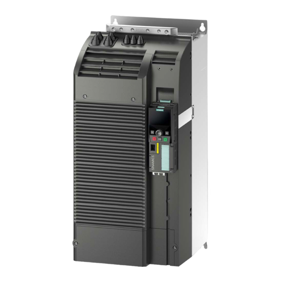
Control Units, Control Unit Adapters and operating components Introduction 7.1.1 Control Units Brief description The CU310-2 Controller Units are designed for operation connected to a Power Module, in the blocksize or chassis formats. CU310-2 DP CU310-2 PN AC Drive Manual, (GH6), 07/2016, 6SL3097-4AL00-0BP5... - Page 218 Control Units, Control Unit Adapters and operating components 7.1 Introduction Features Designation Features Article number - PROFIBUS as an external communications interface CU310-2 DP - LAN (Ethernet) 6SL3040-1LA00-0AA0 - TTL/HTL/SSI – encoder evaluation - analog setpoint input - 2x PROFINET as an external communications interface CU310-2 PN - LAN (Ethernet) 6SL3040-1LA01-0AA0...
- Page 219 Control Units, Control Unit Adapters and operating components 7.1 Introduction ① Memory card ② Blanking plate Figure 7-1 CU310-2 DP: CompactFlash Card slot AC Drive Manual, (GH6), 07/2016, 6SL3097-4AL00-0BP5...
-
Page 220: Control Unit Adapter
Control Units, Control Unit Adapters and operating components 7.1 Introduction 7.1.2 Control Unit Adapter Brief description Using a Control Unit Adapter, a Power Module can be connected as an additional axis to an existing DC/AC group. A higher-level closed-loop control module is always required. Control Unit Adapter CUA31 Control Unit Adapter CUA32 Features... -
Page 221: Safety Instructions For Control Units And Control Unit Adapters
Control Units, Control Unit Adapters and operating components 7.2 Safety instructions for Control Units and Control Unit Adapters Safety instructions for Control Units and Control Unit Adapters WARNING Danger to life if the fundamental safety instructions and residual risks are not observed The non-observance of the fundamental safety instructions and residual risks stated in Chapter 1 can result in accidents with severe injuries or death. - Page 222 Damage or malfunctions can occur on the devices or system when DRIVE-CLiQ cables are used that are either incorrect or have not been approved for this purpose. • Only use suitable DRIVE-CLiQ cables that have been approved by Siemens for the particular application.
-
Page 223: Control Unit Cu310-2 Pn (Profinet)
Control Units, Control Unit Adapters and operating components 7.3 Control Unit CU310-2 PN (PROFINET) Control Unit CU310-2 PN (PROFINET) 7.3.1 Description The Control Unit CU310-2 PN (PROFINET) is a control module for single drives in which the open-loop and closed-loop control functions of the drive are implemented. It controls the Power Modules in the blocksize format via the PM-IF interface and is mounted directly on the Power Module. -
Page 224: Interface Description
Control Units, Control Unit Adapters and operating components 7.3 Control Unit CU310-2 PN (PROFINET) 7.3.2 Interface description 7.3.2.1 Overview Figure 7-2 CU310-2 PN overview of interfaces Note The PROFIBUS address switch on the CU310-2 PN has no function. AC Drive Manual, (GH6), 07/2016, 6SL3097-4AL00-0BP5... -
Page 225: X22 Serial Interface (Rs232)
Control Units, Control Unit Adapters and operating components 7.3 Control Unit CU310-2 PN (PROFINET) The interface to the Power Module is located at the rear of the CU310-2 PN. Figure 7-3 CU310-2 PN interface to the Power Module (PM-IF) 7.3.2.2 X22 serial interface (RS232) Table 7- 3 X22 serial interface (RS232) -
Page 226: X23 Htl/Ttl/Ssi Encoder Interface
Control Units, Control Unit Adapters and operating components 7.3 Control Unit CU310-2 PN (PROFINET) 7.3.2.3 X23 HTL/TTL/SSI encoder interface Table 7- 4 X23 HTL/TTL/SSI encoder interface Signal name Technical data +Temp KTY, PT1000 or PTC input SSI_CLK SSI clock, positive SSI_XCLK SSI clock, negative P encoder 5 V / 24 V... - Page 227 AN_SSI_XDAT, BN, RN not connected to X23 See SINAMICS S120/S150 List Manual for setting the mode Other signal levels according to the RS422 specification. The absolute level of the individual signals varies between 0 V and Vcc of the measuring system.
- Page 228 Control Units, Control Unit Adapters and operating components 7.3 Control Unit CU310-2 PN (PROFINET) Encoder cables Encoder type Maximum encoder cable length in m HTL unipolar HTL bipolar up to 100 (depending on the baud rate) 100 m with remote sense Because the transmission technology is more robust, the bipolar connection should always be used.
-
Page 229: X100 Drive-Cliq Interface
Control Units, Control Unit Adapters and operating components 7.3 Control Unit CU310-2 PN (PROFINET) 7.3.2.4 X100 DRIVE-CLiQ interface Table 7- 6 X100 DRIVE-CLiQ interface Signal name Technical data Transmit data + Transmit data - Receive data + Reserved, do not use Reserved, do not use Receive data - Reserved, do not use... - Page 230 Overheating can cause damage to the motor. • Connect a KTY temperature sensor with the correct polarity. Further information regarding the temperature sensor may be found in the SINAMICS S120 Commissioning Manual, "Temperature sensors for SINAMICS components" section.
-
Page 231: X121 Digital Inputs/Outputs
Control Units, Control Unit Adapters and operating components 7.3 Control Unit CU310-2 PN (PROFINET) 7.3.2.6 X121 digital inputs/outputs Table 7- 8 X121 digital inputs and bidirectional digital inputs/outputs Terminal Designation Technical data DI 0 Voltage: -3 … 30 VDC Current consumption, typical: 6 mA at 24 V DI 1 Electrical isolation: via optocoupler DI 2... -
Page 232: X124 Electronics Power Supply
Control Units, Control Unit Adapters and operating components 7.3 Control Unit CU310-2 PN (PROFINET) The maximum cable length that can be connected is 30 m. Note An open input is interpreted as "low". Terminal M2 must be connected so that the digital inputs (DI0 ... DI3) can be used. This is achieved through one of the following measures: •... -
Page 233: X127 Lan (Ethernet)
Control Units, Control Unit Adapters and operating components 7.3 Control Unit CU310-2 PN (PROFINET) Note The two "+" and/or "M" terminals are jumpered in the connector. This ensures that the supply voltage is looped through. The current consumption increases by the value for the DRIVE-CLiQ participant and digital outputs. -
Page 234: X130 Digital Input (Fail Safe) Digital Output
Control Units, Control Unit Adapters and operating components 7.3 Control Unit CU310-2 PN (PROFINET) 7.3.2.9 X130 digital input (fail safe) digital output Table 7- 11 X130 digital input / fail-safe digital output Terminal Designation Technical data DI 22+ Voltage: -3 … 30 VDC Current consumption, typical: 6 mA at 24 V DI 22- Electrical isolation: via optocoupler... -
Page 235: X131 Digital Inputs/Outputs And Analog Input
Control Units, Control Unit Adapters and operating components 7.3 Control Unit CU310-2 PN (PROFINET) 7.3.2.10 X131 digital inputs/outputs and analog input Table 7- 12 X131 bidirectional digital inputs/outputs and analog input Terminal Designation Technical data DI/DO 12 As input: Voltage: -3 … 30 VDC DI/DO 13 Current consumption, typical: 5 mA at 24 V Level (incl. -
Page 236: X150 P1/P2 Profinet
Control Units, Control Unit Adapters and operating components 7.3 Control Unit CU310-2 PN (PROFINET) The maximum cable length that can be connected is 30 m. Note Permissible voltage values at the analog input The common-mode range must not be violated in order to avoid incorrect results of the analog-digital conversion. -
Page 237: Measuring Sockets
Control Units, Control Unit Adapters and operating components 7.3 Control Unit CU310-2 PN (PROFINET) Table 7- 14 LED states on the X150 P1/P2 PROFINET interface Color Status Description Link port Missing or faulty link Green Continuous 10 or 100 Mbit link available light Activity port No activity... -
Page 238: Reset Button
CU310-2 PN Inserting the memory card The memory card in a faulty CU310-2 PN If you are returning a faulty CU310-2 PN to Siemens, remove the memory card and keep it in a safe place. This ensures that all your saved data (firmware, licenses, parameters) will be available to you immediately again to commission a replacement unit. -
Page 239: Connection Examples
Control Units, Control Unit Adapters and operating components 7.3 Control Unit CU310-2 PN (PROFINET) 7.3.3 Connection examples CU310-2 PN without safety function Figure 7-6 Connection example, CU310-2 PN without safety function AC Drive Manual, (GH6), 07/2016, 6SL3097-4AL00-0BP5... - Page 240 Control Units, Control Unit Adapters and operating components 7.3 Control Unit CU310-2 PN (PROFINET) CU310-2 PN with safety function Figure 7-7 Connection example, CU310-2 PN with safety function AC Drive Manual, (GH6), 07/2016, 6SL3097-4AL00-0BP5...
-
Page 241: Meaning Of The Leds
Control Units, Control Unit Adapters and operating components 7.3 Control Unit CU310-2 PN (PROFINET) 7.3.4 Meaning of the LEDs 7.3.4.1 Function of the LEDs There are four LEDs on the front panel of the CU310-2 PN's housing (see CU310-2 PN Interface Overview (Page 224).) Table 7- 17 LEDs... -
Page 242: Behavior Of The Leds In The Operating State
Waiting for POWER ON of the component. corresponding components. Green/oran Flashing light Recognition of the component via LED is 2 Hz activated (see SINAMICS S120/S150 List Manual.) red/orange Note: Both options depend on the LED status when component recognition is activated. AC Drive... - Page 243 Control Units, Control Unit Adapters and operating components 7.3 Control Unit CU310-2 PN (PROFINET) Color State Description / cause Remedy Cyclic communication has not (yet) taken place. Note: PROFIdrive is ready for communication when the Control Unit is ready (see LED: RDY). Continuous light Cyclic communication is taking place.
-
Page 244: Dimension Drawing
Control Units, Control Unit Adapters and operating components 7.3 Control Unit CU310-2 PN (PROFINET) 7.3.5 Dimension drawing Figure 7-8 Dimension drawing, Control Unit CU310-2 PN, all data in mm (inches) AC Drive Manual, (GH6), 07/2016, 6SL3097-4AL00-0BP5... -
Page 245: Technical Data
The response time of digital inputs/outputs depends on the evaluation. Weight 0.95 You will find information on this topic in the SINAMICS S120/S150 List Manual, Chapter "Function block diagrams." Control Unit CU310-2 DP (PROFIBUS) 7.4.1 Description The CU310-2 DP Control Unit (PROFIBUS) is a control module for single-motor drives in which the open-loop and closed-loop control functions of the drive are implemented. -
Page 246: Interface Description
Control Units, Control Unit Adapters and operating components 7.4 Control Unit CU310-2 DP (PROFIBUS) 7.4.2 Interface description 7.4.2.1 Overview Figure 7-9 CU310-2 DP interface overview The interface to the Power Module is located at the rear of the CU310-2 DP. Figure 7-10 CU310-2 DP interface to the Power Module (PM-IF) AC Drive... -
Page 247: X21 Profibus
Control Units, Control Unit Adapters and operating components 7.4 Control Unit CU310-2 DP (PROFIBUS) 7.4.2.2 X21 PROFIBUS The PROFIBUS interface X21 can be operated isochronously. Table 7- 23 X21 PROFIBUS interface Signal name Meaning Range Not assigned M24_SERV Teleservice supply, ground RxD/TxD-P Receive/transmit data P (B) RS485... -
Page 248: Profibus Address Switch
The factory setting for the rotary coding switches is 0 The PROFIBUS address is set as follows: 1. via a parameter (see SINAMICS S120/S150 List Manual) – To set the bus address for a PROFIBUS node using STARTER, first set the rotary... -
Page 249: X22 Serial Interface (Rs232)
Control Units, Control Unit Adapters and operating components 7.4 Control Unit CU310-2 DP (PROFIBUS) 7.4.2.4 X22 serial interface (RS232) Table 7- 25 X22 serial interface (RS232) Signal name Technical data Reserved, do not use XRXD_RS232 Receive data XTXD_RS232 Transmit data Reserved, do not use Ground Reserved, do not use... -
Page 250: X23 Htl/Ttl/Ssi Encoder Interface
Control Units, Control Unit Adapters and operating components 7.4 Control Unit CU310-2 DP (PROFIBUS) 7.4.2.5 X23 HTL/TTL/SSI encoder interface Table 7- 26 X23 HTL/TTL/SSI encoder interface Signal name Technical data +Temp KTY, PT1000 or PTC input SSI_CLK SSI clock, positive SSI_XCLK SSI clock, negative P encoder 5 V / 24 V... - Page 251 AN_SSI_XDAT, BN, RN not connected to X23 See SINAMICS S120/S150 List Manual for setting the mode Other signal levels according to the RS422 specification. The absolute level of the individual signals varies between 0 V and Vcc of the measuring system.
- Page 252 Control Units, Control Unit Adapters and operating components 7.4 Control Unit CU310-2 DP (PROFIBUS) Encoder cables Encoder type Maximum encoder cable length in m HTL unipolar HTL bipolar up to 100 (depending on the baud rate) 100 m with remote sense Because the transmission technology is more robust, the bipolar connection should always be used.
-
Page 253: X100 Drive-Cliq Interface
Control Units, Control Unit Adapters and operating components 7.4 Control Unit CU310-2 DP (PROFIBUS) 7.4.2.6 X100 DRIVE-CLiQ interface Table 7- 28 X100 DRIVE-CLiQ interface Signal name Technical data Transmit data + Transmit data - Receive data + Reserved, do not use Reserved, do not use Receive data - Reserved, do not use... - Page 254 Overheating can cause damage to the motor. • Connect a KTY temperature sensor with the correct polarity. Further information regarding the temperature sensor may be found in the SINAMICS S120 Commissioning Manual, "Temperature sensors for SINAMICS components" section.
-
Page 255: X121 Digital Inputs/Outputs
Control Units, Control Unit Adapters and operating components 7.4 Control Unit CU310-2 DP (PROFIBUS) 7.4.2.8 X121 digital inputs/outputs Table 7- 30 X121 digital inputs and bidirectional digital inputs/outputs Terminal Designation Technical data DI 0 Voltage: -3 … 30 VDC Current consumption, typical: 6 mA at 24 V DI 1 Electrical isolation: via optocoupler DI 2... -
Page 256: X124 Electronics Power Supply
Control Units, Control Unit Adapters and operating components 7.4 Control Unit CU310-2 DP (PROFIBUS) The maximum cable length that can be connected is 30 m. Note An open input is interpreted as "low". Terminal M2 must be connected so that the digital inputs (DI0 ... DI3) can be used. This is achieved through one of the following measures: •... -
Page 257: X127 Lan (Ethernet)
Control Units, Control Unit Adapters and operating components 7.4 Control Unit CU310-2 DP (PROFIBUS) Note The two "+" and/or "M" terminals are jumpered in the connector. This ensures that the supply voltage is looped through. The current consumption increases by the value for the DRIVE-CLiQ participant and digital outputs. -
Page 258: X130 Digital Input (Fail Safe) Digital Output
Control Units, Control Unit Adapters and operating components 7.4 Control Unit CU310-2 DP (PROFIBUS) 7.4.2.11 X130 digital input (fail safe) digital output Table 7- 33 X130 digital input / fail-safe digital output Terminal Designation Technical data DI 22+ Voltage: -3 … 30 VDC Current consumption, typical: 6 mA at 24 V DI 22- Electrical isolation: via optocoupler... -
Page 259: X131 Digital Inputs/Outputs And Analog Input
Control Units, Control Unit Adapters and operating components 7.4 Control Unit CU310-2 DP (PROFIBUS) 7.4.2.12 X131 digital inputs/outputs and analog input Table 7- 34 X131 bidirectional digital inputs/outputs and analog input Terminal Designation Technical data DI/DO 12 As input: Voltage: -3 … 30 VDC DI/DO 13 Current consumption, typical: 5 mA at 24 V Level (incl. -
Page 260: Measuring Sockets
Control Units, Control Unit Adapters and operating components 7.4 Control Unit CU310-2 DP (PROFIBUS) The maximum cable length that can be connected is 30 m. Note Permissible voltage values at the analog input The common-mode range must not be violated in order to avoid incorrect results of the analog-digital conversion. -
Page 261: S5 Dip Switch
Control Units, Control Unit Adapters and operating components 7.4 Control Unit CU310-2 DP (PROFIBUS) 7.4.2.14 S5 DIP switch DIP switch S5 is used to switch the analog input between voltage input or current input. It is located under the blanking cover (see CU310-2 PN Interface Overview (Page 224).) Table 7- 36 DIP switch S5 - switchover between voltage/current Switch... -
Page 262: Memory Card
CU310-2 DP Inserting the memory card The memory card in a faulty CU310-2 DP If you are returning a faulty CU310-2 DP to Siemens, remove the memory card and keep it in a safe place. This ensures that all your saved data (firmware, licenses, parameters) will be available to you immediately again to commission a replacement unit. -
Page 263: Connection Examples
Control Units, Control Unit Adapters and operating components 7.4 Control Unit CU310-2 DP (PROFIBUS) 7.4.3 Connection examples CU310-2 DP without safety function Figure 7-13 Connection example, CU310-2 DP without safety function AC Drive Manual, (GH6), 07/2016, 6SL3097-4AL00-0BP5... - Page 264 Control Units, Control Unit Adapters and operating components 7.4 Control Unit CU310-2 DP (PROFIBUS) CU310-2 DP with safety function Figure 7-14 Connection example, CU310-2 DP with safety function AC Drive Manual, (GH6), 07/2016, 6SL3097-4AL00-0BP5...
-
Page 265: Meaning Of The Leds
Control Units, Control Unit Adapters and operating components 7.4 Control Unit CU310-2 DP (PROFIBUS) 7.4.4 Meaning of the LEDs 7.4.4.1 Function of the LEDs There are 4 LEDs on the front panel of the CU310-2 DP housing (see CU310-2 DP interface overview (Page 246).) Table 7- 37 LEDs... -
Page 266: Behavior Of The Leds In The Operating State
Green/oran Flashing light Recognition of the component via LED is activated 2 Hz (see SINAMICS S120/S150 List Manual). Note: red/orange Both possibilities depend on the status of the LED when activating. AC Drive Manual, (GH6), 07/2016, 6SL3097-4AL00-0BP5... - Page 267 Control Units, Control Unit Adapters and operating components 7.4 Control Unit CU310-2 DP (PROFIBUS) Color State Description / cause Remedy Cyclic communication is not (yet) running. Note: The PROFIdrive is ready for communication when the Control Unit is ready for operation (see LED: RDY).
-
Page 268: Dimension Drawing
Control Units, Control Unit Adapters and operating components 7.4 Control Unit CU310-2 DP (PROFIBUS) 7.4.5 Dimension drawing Figure 7-15 Dimension drawing, Control Unit CU310-2 DP, all data in mm (inches) AC Drive Manual, (GH6), 07/2016, 6SL3097-4AL00-0BP5... -
Page 269: Technical Data
The response time of digital inputs/outputs depends on the evaluation. Weight 0.95 You will find information on this topic in the SINAMICS S120/S150 List Manual, Chapter "Function block diagrams". Control Unit Adapter CUA31 7.5.1 Description The CUA31 Control Unit Adapter is used to connect a Power Module blocksize to an existing DC/AC group with a higher-level control module, e.g. -
Page 270: Interface Description
Control Units, Control Unit Adapters and operating components 7.5 Control Unit Adapter CUA31 7.5.2 Interface description 7.5.2.1 Overview Figure 7-16 Interface overview of the CUA31 AC Drive Manual, (GH6), 07/2016, 6SL3097-4AL00-0BP5... -
Page 271: X200-X202 Drive-Cliq Interfaces
Input current: typ. 4 mA at 24 V DC Type: Screw-type terminal 1 (Page 371) Max. cross-section that can be connected 1.5 mm Further information regarding the temperature sensor may be found in the SINAMICS S120 Commissioning Manual, Section "Temperature sensors for SINAMICS components." AC Drive... -
Page 272: X224 Electronics Power Supply
Control Units, Control Unit Adapters and operating components 7.5 Control Unit Adapter CUA31 Temperature sensor input The temperature sensor is required for motors where the temperature value is not transmitted via DRIVE-CLiQ. NOTICE Damage to motor in the event of incorrectly connected KTY temperature sensor If a KTY temperature sensor is connected with incorrect polarity, it is not possible to detect when the motor overheats. -
Page 273: Connection Example
The component is ready for operation and cyclic DRIVE-CLiQ communication is taking place. Cause and rectification of faults Information about the cause and rectification of faults can be found in the SINAMICS S120 Commissioning Manual. AC Drive Manual, (GH6), 07/2016, 6SL3097-4AL00-0BP5... -
Page 274: Dimension Drawing
Control Units, Control Unit Adapters and operating components 7.5 Control Unit Adapter CUA31 7.5.5 Dimension drawing Figure 7-18 Dimension drawing of Control Unit Adapter CUA31, all data in mm and (inches) 7.5.6 Technical data Table 7- 47 Technical data CUA31 6SL3040-0PA00-0AA0 / 6SL3040-0PA00-0AA1 Unit Value... -
Page 275: Control Unit Adapter Cua32
Control Units, Control Unit Adapters and operating components 7.6 Control Unit Adapter CUA32 Control Unit Adapter CUA32 7.6.1 Description The Control Unit Adapter CUA32 is used to connect a Power Module blocksize to an existing DC/AC group with a higher-level control module, e.g. a CU320-2. Since the closed-loop control is realized externally, for operation, a SINAMICS, SIMOTION, or SINUMERIK closed- loop control is always required for several axes. -
Page 276: Interface Description
Control Units, Control Unit Adapters and operating components 7.6 Control Unit Adapter CUA32 7.6.2 Interface description 7.6.2.1 Overview Figure 7-19 Interface overview CUA32 AC Drive Manual, (GH6), 07/2016, 6SL3097-4AL00-0BP5... -
Page 277: X200-X202 Drive-Cliq Interfaces
Input current: typ. 4 mA at 24 V DC Type: Screw-type terminal 1 (Page 371) Max. cross-section that can be connected 1.5 mm Further information regarding the temperature sensor may be found in the SINAMICS S120 Commissioning Manual, Section "Temperature sensors for SINAMICS components." AC Drive... - Page 278 Control Units, Control Unit Adapters and operating components 7.6 Control Unit Adapter CUA32 Temperature sensor input The temperature sensor is required for motors where the temperature value is not transmitted via DRIVE-CLiQ. NOTICE Damage to motor in the event of incorrectly connected KTY temperature sensor If a KTY temperature sensor is connected with incorrect polarity, it is not possible to detect when the motor overheats.
-
Page 279: X220 Htl/Ttl/Ssi Encoder Interface
Control Units, Control Unit Adapters and operating components 7.6 Control Unit Adapter CUA32 7.6.2.4 X220 HTL/TTL/SSI encoder interface Table 7- 51 X220 HTL/TTL/SSI encoder interface Signal name Technical data +Temp KTY, PT1000 or PTC input SSI_CLK SSI clock, positive SSI_XCLK SSI clock, negative P encoder 5 V / 24 V Encoder power supply... -
Page 280: X224 Electronics Power Supply
Control Units, Control Unit Adapters and operating components 7.6 Control Unit Adapter CUA32 Parameter Designation Threshold Min. Type Max. Unit High signal level Hdiff (SSI bipolar at X220) Low signal level Ldiff (SSI bipolar at X220) Signal frequency Edge clearance Zero pulse (with T = 1/f Length... -
Page 281: Connection Example
If an encoder that is designed for a 5 V power supply is operated with a 24 V power supply, this can destroy the encoder electronics. Cause and rectification of faults Information about the cause and rectification of faults can be found in the SINAMICS S120 Commissioning Manual. AC Drive... -
Page 282: Dimension Drawing
Control Units, Control Unit Adapters and operating components 7.6 Control Unit Adapter CUA32 7.6.5 Dimension drawing Figure 7-21 Dimension drawing of Control Unit Adapter CUA32, all data in mm and (inches) 7.6.6 Technical data Table 7- 55 Technical data CUA32 6SL3040-0PA01-0AA0 Unit Value... -
Page 283: Mounting Control Units And Control Unit Adapters
Control Units, Control Unit Adapters and operating components 7.7 Mounting Control Units and Control Unit Adapters Mounting Control Units and Control Unit Adapters Power Modules Blocksize Control Unit (CU310-2 PN/DP) and Control Unit Adapter (CUA31/CUA32) can be mounted onto Power Modules Blocksize of any frame size. Communication between the devices is realized via the PM-IF interface. -
Page 284: Basic Operator Panel Bop20
Control Units, Control Unit Adapters and operating components 7.8 Basic Operator Panel BOP20 Basic Operator Panel BOP20 7.8.1 Description The Basic Operator Panel BOP20 is a basic operator panel with six keys and a backlit display unit. The BOP20 can be inserted on the CU310-2 DP and CU310-2 PN SINAMICS Control Units and operated. - Page 285 Control Units, Control Unit Adapters and operating components 7.8 Basic Operator Panel BOP20 Overview of displays and keys Figure 7-24 Overview of displays and keys Table 7- 56 Displays Display Meaning Top left The active drive object of the BOP is displayed here. 2 positions The displays and key operations always refer to this drive object.
- Page 286 Control Units, Control Unit Adapters and operating components 7.8 Basic Operator Panel BOP20 BOP20 keyboard Table 7- 57 Assignment of the BOP20 keyboard Name Meaning Powering-up the drives for which the command "ON/OFF1", "OFF2" or "OFF3" should come from the BOP. Power-down the drives for which the "ON/OFF1,"...
-
Page 287: Mounting
Control Units, Control Unit Adapters and operating components 7.8 Basic Operator Panel BOP20 7.8.3 Mounting NOTICE Damage when using the BOP The interface for the BOP20 on the CU310-2 may be damaged when the BOP20 is used. • Make sure that you insert and withdraw the BOP20 straight into/out of the CU310-2 and that it is not tilted up or down. - Page 288 3. Insert the blanking cover. Display and operator controls of the BOP20 Additional information on the display and operating elements of the BOP20 can be taken from the following reference: Reference: /IH1/ SINAMICS S120 Commissioning Manual with STARTER AC Drive Manual, (GH6), 07/2016, 6SL3097-4AL00-0BP5...
-
Page 289: Supplementary System Components And Encoder System Integration
When opening plug connections in operation, arcs can result in severe injury or death. • Disconnect or connect the encoder cables to Siemens motors, which are not expressly released for connecting and disconnecting during operation, in a deenergized condition only. - Page 290 Damage caused by the use of incorrect DRIVE-CLiQ cables The use of incorrect or not released DRIVE-CLiQ cables can cause damage or functional faults to devices or the system. • Use only appropriate DRIVE-CLiQ cables that have been approved by Siemens for the use case in question. Note...
-
Page 291: Sensor Module Cabinet-Mounted Smc10
Supplementary system components and encoder system integration 8.1 Sensor Modules 8.1.2 Sensor Module Cabinet-Mounted SMC10 8.1.2.1 Description The Sensor Module Cabinet-Mounted SMC10 is an expansion module for snapping on to a standard mounting rail acc. to EN 60715. It evaluates encoder signals and transmits the speed, actual position value, rotor position and, if necessary, the motor temperature via DRIVE-CLiQ to the Control Unit. - Page 292 Supplementary system components and encoder system integration 8.1 Sensor Modules X500 DRIVE-CLiQ interface Table 8- 1 X500: DRIVE-CLiQ interface Signal name Technical data Transmit data + Transmit data - Receive data + Reserved, do not use Reserved, do not use Receive data - Reserved, do not use Reserved, do not use...
- Page 293 Supplementary system components and encoder system integration 8.1 Sensor Modules X520 encoder system interface Table 8- 2 X520: Encoder system interface Signal name Technical data Reserved, do not use Reserved, do not use Resolver signal A (sin+) Inverted resolver signal A (sin-) Ground Ground (for internal shield) Resolver signal B (cos+)
- Page 294 8.1 Sensor Modules Data regarding the parameterization of the KTY temperature sensor can be taken from the following reference: Reference: /FH1/ SINAMICS S120 Function Manual, Chapter "Monitoring and protective functions/thermal motor protection" WARNING Danger to life due to electric shock in the event of voltage flashovers at the temperature...
-
Page 295: Meaning Of The Leds
Cause and rectification of faults Additional information about the cause and resolving faults can be taken from the following references: ● Reference:/LH1/SINAMICS S120/S150 List Manual ● Reference: /IH1/ SINAMICS S120 Commissioning Manual with STARTER AC Drive Manual, (GH6), 07/2016, 6SL3097-4AL00-0BP5... -
Page 296: Dimension Drawing
Supplementary system components and encoder system integration 8.1 Sensor Modules 8.1.2.4 Dimension drawing Figure 8-2 Dimension drawing of the Sensor Module Cabinet SMC10, all dimensions in mm and (inches) AC Drive Manual, (GH6), 07/2016, 6SL3097-4AL00-0BP5... -
Page 297: Mounting
Supplementary system components and encoder system integration 8.1 Sensor Modules 8.1.2.5 Mounting Installation 1. Tilt the component backwards slightly and attach it to the DIN rail using the hooks. 2. Swivel the component onto the DIN rail until you hear the mounting slide at the rear latch into position. -
Page 298: Technical Data
Supplementary system components and encoder system integration 8.1 Sensor Modules 8.1.2.6 Technical data Table 8- 5 Technical data 6SL3055-0AA00-5AA. Unit Value Electronics power supply Voltage 24 (20.4 … 28.8) Current (without encoder system) ≤ 0.20 Current (with encoder system) ≤ 0.35 Power loss ≤... - Page 299 Supplementary system components and encoder system integration 8.1 Sensor Modules Figure 8-4 Rotor impedances that can be connected with excitation frequency f = 5000 Hz To check as shown in the figure above, the impedances Z or Z (impedance between R1 and R2 with short-circuited or open outputs) from the encoder manufacturer's data sheet must be used.
-
Page 300: Sensor Module Cabinet-Mounted Smc20
Supplementary system components and encoder system integration 8.1 Sensor Modules 8.1.3 Sensor Module Cabinet-Mounted SMC20 8.1.3.1 Description The Sensor Module Cabinet-Mounted SMC20 is an expansion module for snapping on to a standard mounting rail acc. to EN 60715. It evaluates encoder signals and transmits the speed, actual position, rotor position and, if applicable, the motor temperature and reference point via DRIVE-CLiQ to the Control Unit. - Page 301 Supplementary system components and encoder system integration 8.1 Sensor Modules X500 DRIVE-CLiQ interface Table 8- 7 X500: DRIVE-CLiQ interface Signal name Technical data Transmit data + Transmit data - Receive data + Reserved, do not use Reserved, do not use Receive data - Reserved, do not use Reserved, do not use...
- Page 302 Supplementary system components and encoder system integration 8.1 Sensor Modules X520 encoder system interface Table 8- 8 X520: Encoder system interface Signal name Technical data P encoder Encoder power supply M encoder Ground for encoder power supply Incremental signal A Inverse incremental signal A Ground Ground (for internal shield)
- Page 303 • Connect a KTY temperature sensor with the correct polarity. Data regarding the parameterization of the KTY temperature sensor can be taken from the following reference: Reference: /FH1/ SINAMICS S120 Function Manual, Chapter "Monitoring and protective functions/thermal motor protection" WARNING...
-
Page 304: Meaning Of The Leds
Cause and rectification of faults Additional information about the cause and resolving faults can be taken from the following references: ● Reference:/LH1/SINAMICS S120/S150 List Manual ● Reference: /IH1/ SINAMICS S120 Commissioning Manual with STARTER AC Drive Manual, (GH6), 07/2016, 6SL3097-4AL00-0BP5... -
Page 305: Dimension Drawing
Supplementary system components and encoder system integration 8.1 Sensor Modules 8.1.3.4 Dimension drawing Figure 8-6 Dimension drawing of the Sensor Module Cabinet SMC20, all data in mm and (inches) AC Drive Manual, (GH6), 07/2016, 6SL3097-4AL00-0BP5... -
Page 306: Mounting
Supplementary system components and encoder system integration 8.1 Sensor Modules 8.1.3.5 Mounting Installation 1. Tilt the component backwards slightly and attach it to the DIN rail using the hooks. 2. Swivel the component onto the DIN rail until you hear the mounting slide at the rear latch into position. -
Page 307: Technical Data
Supplementary system components and encoder system integration 8.1 Sensor Modules 8.1.3.6 Technical data Table 8- 11 Technical data 6SL3055-0AA00-5BA. Unit Value Electronics power supply Voltage 24 (20.4 … 28.8) Current (without encoder system) ≤ 0.20 Current (with encoder system) ≤ 0.35 Power loss ≤... -
Page 308: Sensor Module Cabinet-Mounted Smc30
Supplementary system components and encoder system integration 8.1 Sensor Modules 8.1.4 Sensor Module Cabinet-Mounted SMC30 8.1.4.1 Description The Sensor Module Cabinet-Mounted SMC30 is an expansion module for snapping on to a standard mounting rail acc. to EN 60715. It evaluates encoder signals and transmits the speed, actual position, and, if applicable, the motor temperature and reference point via DRIVE-CLiQ to the Control Unit. - Page 309 Supplementary system components and encoder system integration 8.1 Sensor Modules X500 DRIVE-CLiQ interface Table 8- 12 X500: DRIVE-CLiQ interface Signal name Technical data Transmit data + Transmit data - Receive data + Reserved, do not use Reserved, do not use Receive data - Reserved, do not use Reserved, do not use...
- Page 310 Supplementary system components and encoder system integration 8.1 Sensor Modules X520 encoder system interface Table 8- 13 X520: Encoder system interface Signal name Technical data + Temp Temperature sensor KTY84-1C130 / PT1000 / PTC Clock SSI clock Clock* Inverse SSI clock P encoder 5 V / 24 V Encoder power supply P encoder 5 V / 24 V...
- Page 311 8.1 Sensor Modules Data regarding the parameterization of the KTY temperature sensor can be taken from the following reference: Reference: /FH1/ SINAMICS S120 Function Manual, Chapter "Monitoring and protective functions/thermal motor protection" WARNING Danger to life due to electric shock in the event of voltage flashovers at the temperature...
- Page 312 Supplementary system components and encoder system integration 8.1 Sensor Modules X521 / X531 alternative encoder system interface Table 8- 14 X521/X531: Alternative encoder system interface Designation Technical data X521 Incremental signal A Inverse incremental signal A Incremental signal B Inverse incremental signal B Reference signal R Inverse reference signal R CTRL...
- Page 313 • Connect a KTY temperature sensor with the correct polarity. Data regarding the parameterization of the KTY temperature sensor can be taken from the following reference: Reference: /FH1/ SINAMICS S120 Function Manual, Chapter "Monitoring and protective functions/thermal motor protection" Note The maximum length of the temperature sensor cable is 100 m.
-
Page 314: Connection Examples
Supplementary system components and encoder system integration 8.1 Sensor Modules X524 Electronics power supply Table 8- 15 X524: Electronics power supply Terminal Function Technical data Electronics power supply Voltage: 24 V (20.4 … 28.8 V) Electronics power supply Current consumption: max. 0.55 A Max. - Page 315 Supplementary system components and encoder system integration 8.1 Sensor Modules Connection example 2: HTL encoder, unipolar, with reference signal Figure 8-11 Connection example 2: HTL encoder, unipolar, with reference signal Because the physical transmission media is more robust, the bipolar connection should always be used.
-
Page 316: Meaning Of The Leds
Cause and rectification of faults Additional information about the cause and resolving faults can be taken from the following references: ● Reference:/LH1/SINAMICS S120/S150 List Manual ● Reference: /IH1/ SINAMICS S120 Commissioning Manual with STARTER AC Drive Manual, (GH6), 07/2016, 6SL3097-4AL00-0BP5... -
Page 317: Dimension Drawing
Supplementary system components and encoder system integration 8.1 Sensor Modules 8.1.4.5 Dimension drawing Figure 8-13 Dimension drawing of the Sensor Module Cabinet SMC30, all data in mm and (inches) AC Drive Manual, (GH6), 07/2016, 6SL3097-4AL00-0BP5... -
Page 318: Mounting
Supplementary system components and encoder system integration 8.1 Sensor Modules 8.1.4.6 Mounting Installation 1. Tilt the component backwards slightly and attach it to the DIN rail using the hooks. 2. Swivel the component onto the DIN rail until you hear the mounting slide at the rear latch into position. -
Page 319: Protective Conductor Connection And Shield Support
Supplementary system components and encoder system integration 8.1 Sensor Modules 8.1.4.7 Protective conductor connection and shield support Shield contacts are only required if the system is connected to X521/X531. ① Protective conductor connection with M4 screw / 1.8 Nm ② Shield connection terminal, Weidmüller company, type: KLBUE CO1, Article number: 1753311001 Figure 8-15... - Page 320 Supplementary system components and encoder system integration 8.1 Sensor Modules 6SL3055-0AA00-5CA2 Unit Value SSI baud rate 100 - 1000 PE/ground connection At the housing with M4 screw Weight 0.45 A controller compares the encoder system supply voltage - sensed via the Remote Sense cables - with the reference supply voltage of the encoder system, and adjusts the supply voltage for the encoder system at the output of the sensor module until the required supply voltage is obtained directly at the encoder system (only for 5 V encoder system power supply).
- Page 321 Supplementary system components and encoder system integration 8.1 Sensor Modules Table 8- 19 Encoders that can be connected X520 X521 X531 Track Remote Sense (SUB-D) (terminal) (terminal) monitoring HTL bipolar 24 V HTL unipolar 24 V Yes (however, a bipolar connection is recommended) TTL bipolar 24 V TTL bipolar 5 V...
- Page 322 Supplementary system components and encoder system integration 8.1 Sensor Modules SSI encoder Figure 8-16 Maximum cable lengths depending on the SSI baud rate for SSI encoders Encoders with 5 V supply connected to X521/X531 For encoders with a 5 V supply at X521/X531, the cable length depends on the encoder current (for 0.5 mm cable cross-sections): Figure 8-17...
- Page 323 Supplementary system components and encoder system integration 8.1 Sensor Modules Encoders without Remote Sense When encoders without Remote Sense are used, the permissible cable length is limited to 100 m max. because the voltage drop depends on the cable length and the encoder current. Figure 8-18 Signal characteristic of track A and track B between two edges: Time between two edges with pulse encoders...
-
Page 324: Option Module Safe Brake Relay
• Set the DC power supply to 26 V. This ensures that the power supply for the brake remains within the permissible range when the following conditions are met: – Use of Siemens three-phase motors – Use of Siemens MOTION-CONNECT power cables – Motor cable lengths: max. 100 m AC Drive... -
Page 325: Interface Description
Supplementary system components and encoder system integration 8.2 Option module Safe Brake Relay 8.2.3 Interface description 8.2.3.1 Overview ① Connection for the solenoid of the motor brake ② Connection for the 24 VDC power supply ③ Connection for the pre-fabricated (CTRL) to the Power Module, Blocksize format Figure 8-20 Interface description: Safe Brake Relay 8.2.3.2... -
Page 326: Brake Connection
Supplementary system components and encoder system integration 8.2 Option module Safe Brake Relay 8.2.3.3 Brake connection Table 8- 23 Connector Designation Technical data Brake connection Relay output (close) PE connection M4/3 Nm 8.2.4 Connection example Figure 8-21 Safe Brake Relay connection example AC Drive Manual, (GH6), 07/2016, 6SL3097-4AL00-0BP5... -
Page 327: Dimension Drawing
Supplementary system components and encoder system integration 8.2 Option module Safe Brake Relay 8.2.5 Dimension drawing Figure 8-22 Dimension drawing of Safe Brake Relay, all data in mm and (inches) 8.2.6 Mounting PM240-2 FSA to FSC Power Modules ● Mount the Safe Brake Relay at the rear of the cabinet next to the Power Module. PM240-2 FSD to FSF Power Modules ●... -
Page 328: Safe Brake Adapter Optional Module
Supplementary system components and encoder system integration 8.3 Safe Brake Adapter optional module Safe Brake Adapter optional module 8.3.1 Description The Safe Brake Adapter (SBA) is required to implement Safe Brake Control (SBC) in conjunction with Power Modules in the chassis format. The Safe Brake Control (SBC) is a safety function, that is used in safety-related applications, e.g. -
Page 329: Safety Instructions For Safe Brake Adapters
Supplementary system components and encoder system integration 8.3 Safe Brake Adapter optional module 8.3.2 Safety instructions for Safe Brake Adapters WARNING Danger to life due to release of motor brake when connection cable is damaged If the connection cable between the Safe Brake Adapter and the motor brake is broken or short circuited, this may result in the motor brake being supplied with power and released. -
Page 330: Interface Description
Supplementary system components and encoder system integration 8.3 Safe Brake Adapter optional module 8.3.3 Interface description 8.3.3.1 Overview Figure 8-23 Interface overview, Safe Brake Adapter 230 VAC F2 fuse Type of spare fuse: 2 A, time-lag AC Drive Manual, (GH6), 07/2016, 6SL3097-4AL00-0BP5... -
Page 331: X11 Interface To The Control Interface Module
Supplementary system components and encoder system integration 8.3 Safe Brake Adapter optional module 8.3.3.2 X11 interface to the Control Interface Module Table 8- 25 X11 interface to the Control Interface Module Terminal Signal Description Technical data X11.1 Control channel 1 Connection to Control Interface Board, X46.1 X11.2 Control channel 2... -
Page 332: X15 Fast De-Energization
Supplementary system components and encoder system integration 8.3 Safe Brake Adapter optional module WARNING Fire hazard due to overheating when permissible cable lengths are exceeded Excessively long power cables can cause overheating of components with resulting fire and smoke development. •... -
Page 333: Dimension Drawing
Supplementary system components and encoder system integration 8.3 Safe Brake Adapter optional module 8.3.5 Dimension drawing Figure 8-25 Dimension drawing of Safe Brake Adapter, all data in mm and (inches) 8.3.6 Mounting Safe Brake Adapter The Safe Brake Adapter is designed for mounting on a rail in accordance with EN 60715 Housing cover after replacing the fuse An adhesive label is provided on the housing cover indicating the position of the connector. - Page 334 Supplementary system components and encoder system integration 8.3 Safe Brake Adapter optional module AC Drive Manual, (GH6), 07/2016, 6SL3097-4AL00-0BP5...
-
Page 335: Accessories
Damage through use of incorrect DRIVE-CLiQ cables Damage or malfunctions can occur on the devices or system when incorrect or unreleased DRIVE-CLiQ cables are used. • Only use suitable DRIVE-CLiQ cables that have been released by Siemens for the respective application. AC Drive... -
Page 336: Interface Description
Accessories 9.1 DRIVE-CLiQ cabinet bushings 9.1.2 Interface description 9.1.2.1 Overview DRIVE-CLiQ cabinet bushing for DRIVE-CLiQ cables with DRIVE-CLiQ connectors ① Protective cap, Yamaichi, Article No.: Y-ConAS-24-S ② DRIVE-CLiQ interface on the outside (to connect DRIVE-CLiQ signal cables MOTION- CONNECT with IP67 degree of protection) ③... -
Page 337: Dimension Drawings
Accessories 9.1 DRIVE-CLiQ cabinet bushings 9.1.3 Dimension drawings Figure 9-3 Dimension drawing of the DRIVE-CLiQ cabinet gland, all dimensions in mm and (inches) ① Cabinet panel ② Flange, SW18 Figure 9-4 Dimension drawing of the DRIVE-CLiQ cabinet bushing M12, all dimensions in mm and (inches) AC Drive Manual, (GH6), 07/2016, 6SL3097-4AL00-0BP5... -
Page 338: Installation
Accessories 9.1 DRIVE-CLiQ cabinet bushings 9.1.4 Installation 9.1.4.1 DRIVE-CLiQ cabinet bushing for cables with DRIVE-CLiQ connectors In order to install the DRIVE-CLiQ cabinet gland, you must make a cutout in the control cabinet panel as shown in the diagram below. Figure 9-5 Cutout in the control cabinet, all dimensions in mm and (inches) AC Drive... - Page 339 Accessories 9.1 DRIVE-CLiQ cabinet bushings Installation 1. Insert the DRIVE CLiQ cabinet bushing from the outside of the control cabinet through the cutout in the control cabinet. 2. Attach the DRIVE-CLiQ cabinet bushing to the outer control cabinet panel using 2 M3 screws and 2 nuts.
-
Page 340: Drive-Cliq Cabinet Bushing For Cables With M12 Plug/Socket
Accessories 9.1 DRIVE-CLiQ cabinet bushings 9.1.4.2 DRIVE-CLiQ cabinet bushing for cables with M12 plug/socket Prepare the cabinet panel for mounting the DRIVE-CLiQ cabinet bushing M12 as shown below. The removable O ring can be screwed from the inside or the outside. Mounting from the inside using an O ring that can be screwed ①... -
Page 341: Technical Data
Accessories 9.1 DRIVE-CLiQ cabinet bushings Mounting 1. Insert the DRIVE-CLiQ cabinet bushing through the opening in the cabinet. 2. Fasten the DRIVE-CLiQ cabinet bushing using the associated O ring with a tightening torque of 3-4 Nm ① Flange, SW18 ② Seal ③... -
Page 342: Drive-Cliq Coupling
Damage through use of incorrect DRIVE-CLiQ cables Damage or malfunctions can occur on the devices or system when incorrect or unreleased DRIVE-CLiQ cables are used. • Only use suitable DRIVE-CLiQ cables that have been released by Siemens for the respective application. 9.2.2 Interface description 9.2.2.1... -
Page 343: Dimension Drawing
Accessories 9.2 DRIVE-CLiQ coupling 9.2.3 Dimension drawing Figure 9-11 Dimension drawing of the DRIVE-CLiQ coupling, all dimensions in mm and (inches) 9.2.4 Mounting ① Contact surface Figure 9-12 Hole drilling pattern for installation AC Drive Manual, (GH6), 07/2016, 6SL3097-4AL00-0BP5... -
Page 344: Technical Data
Accessories 9.2 DRIVE-CLiQ coupling Installation 1. Attach the DRIVE-CLiQ coupling to the mounting surface as shown in the drilling pattern. 2. Remove the protective caps of the DRIVE-CLiQ coupling. 3. Latch the DRIVE-CLiQ connectors at both sides of the DRIVE-CLiQ coupling. 9.2.5 Technical data Table 9- 2... -
Page 345: Mounting Frame
Accessories 9.3 Mounting frame Mounting frame 9.3.1 Description With the use and proper installation of Siemens mounting frames, the push through Power Modules achieve degree of protection IP54. Article Nos. ● FSA: 6SL3260-6AA00-0DA0 ● FSB: 6SL3260-6AB00-0DA0 ● FSC: 6SL3260-6AC00-0DA0 The accessories package contains all the necessary nuts and seals. - Page 346 Accessories 9.3 Mounting frame Figure 9-14 Dimension drawing of mounting frame, frame size FSC, all data in mm and (inches) AC Drive Manual, (GH6), 07/2016, 6SL3097-4AL00-0BP5...
-
Page 347: Mounting
Accessories 9.3 Mounting frame 9.3.3 Mounting Note Compliance with the EMC requirements To meet the EMC requirements, make sure the contact surface of the heat sink is free of any paint. Installation steps 1. Make an installation cutout and drill holes for the Power Module and the mounting frame according to the drilling pattern. - Page 348 Accessories 9.3 Mounting frame AC Drive Manual, (GH6), 07/2016, 6SL3097-4AL00-0BP5...
-
Page 349: Cabinet Design And Emc For Components, Blocksize Format
Cabinet design and EMC for components, Blocksize format 10.1 General information SINAMICS S components are available as chassis units with degree of protection IP20 or IPXXB according to IEC 60529 and as open type devices to UL 50. This ensures protection against electric shocks. -
Page 350: Safety Instructions For Control Panel Manufacturing
Cabinet design and EMC for components, Blocksize format 10.2 Safety instructions for control panel manufacturing 10.2 Safety instructions for control panel manufacturing WARNING Danger to life if the fundamental safety instructions and residual risks are not heeded Not observing fundamental safety instructions and residual risks stated in Chapter 1 can result in accidents with severe injuries or death. -
Page 351: Information On Electromagnetic Compatibility (Emc)
● Observance of information about cable shielding and equipotential bonding ● Use of the recommended power and signal cables from Siemens. ● Only use cables from Siemens for the DRIVE-CLiQ connections (see Chapter DRIVE- CLiQ signal cables (Page 361)) AC Drive... -
Page 352: Classification Of Emc Behavior
Cabinet design and EMC for components, Blocksize format 10.3 Information on electromagnetic compatibility (EMC) 10.3.2 Classification of EMC behavior EMC environments and EMC categories are defined as follows in the EMC product standard EN 61800-3: Environments First environment (public systems) An environment that includes domestic premises and establishments that are connected directly to a public low-voltage line supply without the use of an intermediate transformer. - Page 353 ● In conjunction with Smart Line Modules, to reduce symmetrical interference emission, special filters can be used (without capacitors to ground). Interference immunity With reference to interference immunity, SINAMICS S120 units can also be used in the first environment. Note...
-
Page 354: Cable Shielding And Routing
Cabinet design and EMC for components, Blocksize format 10.4 Cable shielding and routing The following general conditions must be observed when used in the first environment: ● The drive system must be installed in compliance with EMC regulations by appropriately trained professionals. - Page 355 Cabinet design and EMC for components, Blocksize format 10.4 Cable shielding and routing ① Rear metal panel ② Clip to secure the shield of the motor and line cable to the rear metal panel ③ Motor cable (shielded) ④ Line supply input (shielded) Figure 10-2 Shielding of a PM240-2 Power Module, frame size FSA Alternatively, the cable shields can be connected to them metal mounting plate using pipe...
-
Page 356: Dc Supply Voltage
Cabinet design and EMC for components, Blocksize format 10.5 24 V DC Supply Voltage Routing 24 V cables When routing 24 V cables, the following must also be observed: ● No more than 1 conductor pair may be bundled together. ●... - Page 357 The DC power supply should be set to 26 V. This ensures that the supply voltage for the brake remains within the permissible range when the following conditions are fulfilled: • Use of Siemens three-phase motors • Use of Siemens MOTION-CONNECT power cables • Motor cable lengths: max. 100 m AC Drive...
-
Page 358: Overcurrent Protection
● Cable routing method according to EN 60204-1 The overcurrent protection devices can be determined according to EN 60204-1. Circuit-breakers from Siemens Catalogs LV 1 and LV 1T are recommended as overcurrent protection devices on the primary side. Miniature circuit-breakers or SITOP select (Article No. 6EP1961-2BA00) are recommended as overcurrent protection devices on the secondary side. -
Page 359: Overvoltage Protection
Typical 24 V current consumption of the components A separate 24 V power supply must be used for the SINAMICS S120 drive line-up. The following table can be used to calculate the 24 VDC power supply. The values for typical current consumption are used as a basis for configuration. -
Page 360: Selecting Power Supply Units
Cabinet design and EMC for components, Blocksize format 10.5 24 V DC Supply Voltage Component Typical current consumption [A Sensor Module External SME20 without/with encoder system 0.15/0.25 SME25 without/with encoder system 0.15/0.25 SME120 without/with encoder system 0.20/0.30 SME125 without/with encoder system 0.20/0.30 10.5.5 Selecting power supply units... -
Page 361: Connection Methods
Cabinet design and EMC for components, Blocksize format 10.6 Connection Methods WARNING Danger to life through a hazardous voltage when connecting an unsuitable power supply Touching live components can result in death or severe injury. • Connect the ground potential to the PE conductor connection. •... -
Page 362: Drive-Cliq Signal Cables Without 24 V Dc Cores
Cabinet design and EMC for components, Blocksize format 10.6 Connection Methods 10.6.1.2 DRIVE-CLiQ signal cables without 24 V DC cores Pre-assembled DRIVE-CLiQ signal cables without 24 V DC cores are used to connect components with DRIVE-CLiQ connection, which have a separate or external 24 V DC power supply. -
Page 363: Motion-Connect Drive-Cliq Signal Cables With Drive-Cliq Connector And M12
DRIVE-CLiQ connection and a direct measuring system equipped with DRIVE-CLiQ ASIC with 8-pin M12 connector. Measuring systems from third-party manufacturers can be directly connected to the SINAMICS S120. Basic cable The pre-assembled basic cable has eight cores, of which four are used for data transmission and two for the 24 V supply. -
Page 364: Comparison Of Drive-Cliq Signal Cables
The maximum permissible total cable length between the measuring system and the DRIVE- CLiQ socket of the SINAMICS S120 device is 30 m. For a longer total cable length, data transfer errors may occur. This is the reason that no additional extension can be connected to a 30 m long basic cable. - Page 365 Cabinet design and EMC for components, Blocksize format 10.6 Connection Methods DRIVE-CLiQ signal cable DRIVE-CLiQ DRIVE-CLiQ DRIVE-CLiQ MOTION-CONNECT 500 MOTION-CONNECT 800PLUS Rated voltage V /V in 30 V 30 V 30 V accordance with EN 50395 Test voltage, rms 500 V 500 V 500 V Operating temperature at the surface...
-
Page 366: Combined Use Of Motion-Connect 500 And Motion-Connect 800Plus
Cabinet design and EMC for components, Blocksize format 10.6 Connection Methods 10.6.1.6 Combined use of MOTION-CONNECT 500 and MOTION-CONNECT 800PLUS In principle, MOTION-CONNECT 500 cables and MOTION-CONNECT 800PLUS cables be used together. Basic cables and extensions for MOTION-CONNECT cables with DRIVE-CLiQ connector and M12 socket can be combined without any restrictions. -
Page 367: Power Cables For Motors
Cabinet design and EMC for components, Blocksize format 10.6 Connection Methods 10.6.2 Power cables for motors 10.6.2.1 Configuring the cable length The ohmic losses of the motor cable must be less than 5 % of the Power Module power rating. Table 10- 10 Maximum cable lengths for Power Modules in the blocksize format Frame size Power Modules without filter... -
Page 368: Comparison Of Motion-Connect Power Cables
20 N/mm Smallest bending radius Permanently installed 5 x D 4 x D Moveable approx. 18 x D approx. 8 x D (Details see SIEMENS Industry Mall (Details see SIEMENS Industry Mall (https://mall.industry.siemens.com/mall/ (https://mall.industry.siemens.com/mall/ de/ww/catalog/products/7519999?activ de/ww/catalog/products/7519999?activ eTab=order®ionUrl=/)) eTab=order®ionUrl=/)) Torsional stress 30°/m absolute... -
Page 369: Current-Carrying Capacity And Derating Factors For Power Cables And Signal Cables
Cabinet design and EMC for components, Blocksize format 10.6 Connection Methods 10.6.3 Current-carrying capacity and derating factors for power cables and signal cables The current-carrying capacity of PVC/PUR-insulated copper cables is specified for routing types B1, B2 and C under continuous operating conditions in the table with reference to an ambient air temperature of 40 °C. - Page 370 Cabinet design and EMC for components, Blocksize format 10.6 Connection Methods Table 10- 14 Current carrying capacity according to IEC 60364-5-52 for 40 °C ambient temperature Cross-section Current carrying capacity, effective; AC 50/60 Hz or DC For routing type Power –...
-
Page 371: Spring-Loaded Terminals
Cabinet design and EMC for components, Blocksize format 10.6 Connection Methods 10.6.4 Spring-loaded terminals Table 10- 16 Spring-loaded terminals Spring-loaded terminal type Connectable cable cross- Rigid 0.2 … 1.5 mm sections Flexible 0.2 … 1.5 mm Flexible with end sleeve without plastic sleeve 0.25 …... -
Page 372: Protective Connection And Equipotential Bonding
Cabinet design and EMC for components, Blocksize format 10.7 Protective connection and equipotential bonding 10.7 Protective connection and equipotential bonding Protective connections The SINAMICS S drive system is designed for use in cabinets with a protective conductor connection. The protective conductor connection of the SINAMICS components must be connected to the protective conductor connection of the control cabinet as follows: Table 10- 18 Conductor cross-section for copper protective connections Line supply cable in mm... - Page 373 Cabinet design and EMC for components, Blocksize format 10.7 Protective connection and equipotential bonding ① Within a machine/system, ensure that the protective conductor for the line feeder cable fulfills at least one of the following conditions: For fixed connection: The protective conductor is routed so that along its complete length it is protected against •...
- Page 374 Cabinet design and EMC for components, Blocksize format 10.7 Protective connection and equipotential bonding Functional equipotential bonding For EMC reasons, the shield of the motor cable should be connected through a large surface area both at the Power Module as well as at the motor. The drive line-up must be arranged on a common bright mounting plate in order to comply with the EMC limit values.
-
Page 375: Information On Control Cabinet Cooling
Cabinet design and EMC for components, Blocksize format 10.8 Information on control cabinet cooling 10.8 Information on control cabinet cooling 10.8.1 General Electrical cabinets can be cooled, using among other things with the following: ● filtered fans ● heat exchangers or ●... - Page 376 Cabinet design and EMC for components, Blocksize format 10.8 Information on control cabinet cooling ① Mounting surface ② Discharged air ① Air intake Figure 10-7 Ventilation clearances AC Drive Manual, (GH6), 07/2016, 6SL3097-4AL00-0BP5...
-
Page 377: Ventilation
Cabinet design and EMC for components, Blocksize format 10.8 Information on control cabinet cooling 10.8.2 Ventilation The SINAMICS equipment is ventilated separately by means of integrated fans and is in some cases cooled by means of natural convection. The cooling air must flow through the components vertically from bottom (cooler region) to top (region heated by operation). - Page 378 Cabinet design and EMC for components, Blocksize format 10.8 Information on control cabinet cooling ① Cooling units. ② Control cabinet Figure 10-8 Examples of cabinet ventilation If air conditioners are used, the relative air humidity of the expelled air increases as the air in the air conditioner cools and may exceed the dew point.
-
Page 379: Power Loss Of Components In Rated Operation
Cabinet design and EMC for components, Blocksize format 10.8 Information on control cabinet cooling 10.8.3 Power loss of components in rated operation 10.8.3.1 General The tables below show the power loss for components during rated operation. The characteristic values apply for the following conditions: ●... -
Page 380: Power Loss For Line Reactors And Line Filters
Cabinet design and EMC for components, Blocksize format 10.8 Information on control cabinet cooling 10.8.3.3 Power loss for line reactors and line filters Table 10- 21 Overview of power loss during rated operation for line reactors and line filters Rated output current I Frame size Line voltage Unit... - Page 381 Cabinet design and EMC for components, Blocksize format 10.8 Information on control cabinet cooling Rated output current I /Unit rating Frame size Line voltage Unit Power loss rated based on I rated 70.0 A/18.5 kW 3 AC 200 … 240 V 0.76 83.0 A/22 kW 3 AC 200 …...
- Page 382 Cabinet design and EMC for components, Blocksize format 10.8 Information on control cabinet cooling Rated output current I /Unit rating Frame size Line voltage Unit Power loss rated based on I rated Power Modules blocksize push through 9.6 A/0.75 kW 1 AC/3 AC 200 …...
-
Page 383: Service And Maintenance
Service and maintenance 11.1 Safety instructions for service and maintenance WARNING Danger to life if the fundamental safety instructions and residual risks are not observed The non-observance of the fundamental safety instructions and residual risks stated in Chapter 1 can result in accidents with severe injuries or death. •... -
Page 384: Service And Maintenance For Components, Blocksize Format
Service and maintenance 11.2 Service and maintenance for components, Blocksize format 11.2 Service and maintenance for components, Blocksize format 11.2.1 Replacing hardware components The following components can be replaced with replacement components with the same Article No.: ● Power Modules ●... - Page 385 Service and maintenance 11.2 Service and maintenance for components, Blocksize format Replacing the fan The fan is available as a spare part and has the article number: 6SL3064-1AC00-0AA0. Disconnect the drive line-up from the power supply. Remove the CU310-2 from the drive line-up (see Chapter Mounting Control Units and Control Unit Adapters (Page 283).) Release the snap hooks on the left and right sides of 4.
-
Page 386: Replacing The Fan On The Pm240-2
Service and maintenance 11.2 Service and maintenance for components, Blocksize format 11.2.3 Replacing the fan on the PM240-2 Fans are available as spare parts for all PM240-2 installation sizes. Note Only trained personnel may replace the fan, observing ESD guidelines. For frame sizes FSA to FSC the fan module is mounted below. -
Page 387: Service And Maintenance For Chassis Format Components
Service and maintenance 11.3 Service and maintenance for Chassis format components Frame sizes FSD … FSF Figure 11-2 Fan replacement PM240-2, frame sizes FSD … FSF Proceed as follows to replace a fan module: 1. Switch-off the Power Module, and wait 5 minutes until the DC link capacitors have been discharged. -
Page 388: Maintenance
The actual intervals at which maintenance procedures are to be performed depend on the installation conditions (cabinet environment) and the operating conditions. Siemens offers its customers support in the form of a service contract. For further details, contact your regional office or sales office. -
Page 389: Installation Equipment
Service and maintenance 11.3 Service and maintenance for Chassis format components 11.3.2 Installation equipment Description The installation equipment is used to install and remove the power blocks for Power Modules in the chassis format. It is placed in front of the module and attached to it. The telescopic guide support allows the withdrawable device to be adjusted according to the height at which the power blocks are installed. -
Page 390: Replacing Components
Service and maintenance 11.3 Service and maintenance for Chassis format components 11.3.3 Replacing components 11.3.3.1 Replacing the Powerblock, Power Module, frame size FX Replacing the powerblock Figure 11-4 Replacing the Powerblock, Power Module, frame size FX AC Drive Manual, (GH6), 07/2016, 6SL3097-4AL00-0BP5... - Page 391 Service and maintenance 11.3 Service and maintenance for Chassis format components Preparatory steps ● Disconnect the drive line-up. ● Make sure the power block is accessible. ● Remove the front cover. Removal The steps for the removal procedure are numbered in accordance with the previous diagram. 1.
- Page 392 Service and maintenance 11.3 Service and maintenance for Chassis format components Installation To reinstall, perform the above steps in reverse order. Note Connecting fiber-optic cables The fiber-optic cable plugs must be re-inserted at their original slot. Fiber-optic cables and sockets are accordingly labeled for correct assignment (U11, U21, U31). Note Connection clip to the interference-suppression capacitor The connection clip to the interference-suppression capacitor is mounted on the spare power...
-
Page 393: Replacing The Powerblock, Power Module, Frame Size Gx
Service and maintenance 11.3 Service and maintenance for Chassis format components 11.3.3.2 Replacing the Powerblock, Power Module, frame size GX Replacing the powerblock Figure 11-5 Replacing the Powerblock, Power Module, frame size GX AC Drive Manual, (GH6), 07/2016, 6SL3097-4AL00-0BP5... - Page 394 Service and maintenance 11.3 Service and maintenance for Chassis format components Preparatory steps ● Disconnect the drive line-up. ● Make sure the power block is accessible. ● Remove the front cover. Removal The steps for the removal procedure are numbered in accordance with the previous diagram. 1.
- Page 395 Service and maintenance 11.3 Service and maintenance for Chassis format components Installation To reinstall, perform the above steps in reverse order. Note Connecting fiber-optic cables The fiber-optic cable plugs must be re-inserted at their original slot. Fiber-optic cables and sockets are accordingly labeled for correct assignment (U11, U21, U31). Note Connection clip to the interference-suppression capacitor The connection clip to the interference-suppression capacitor is mounted on the spare power...
-
Page 396: Replacing The Control Interface Module, Power Module, Frame Size Fx
Service and maintenance 11.3 Service and maintenance for Chassis format components 11.3.3.3 Replacing the Control Interface Module, Power Module, frame size FX Replacing the Control Interface Module Figure 11-6 Replacing the Control Interface Module, Power Module, frame size FX AC Drive Manual, (GH6), 07/2016, 6SL3097-4AL00-0BP5... - Page 397 Service and maintenance 11.3 Service and maintenance for Chassis format components Preparatory steps ● Disconnect the drive line-up. ● Make sure the power block is accessible. ● Remove the front cover. Removal The steps for the removal procedure are numbered in accordance with the previous diagram. 1.
-
Page 398: Replacing The Control Interface Module, Power Module, Frame Size Gx
Service and maintenance 11.3 Service and maintenance for Chassis format components 11.3.3.4 Replacing the Control Interface Module, Power Module, frame size GX Replacing the Control Interface Module Figure 11-7 Replacing the Control Interface Module, Power Module, frame size GX AC Drive Manual, (GH6), 07/2016, 6SL3097-4AL00-0BP5... - Page 399 Service and maintenance 11.3 Service and maintenance for Chassis format components Preparatory steps ● Disconnect the drive line-up. ● Make sure the power block is accessible. ● Remove the front cover. Removal The steps for the removal procedure are numbered in accordance with the previous diagram. 1.
-
Page 400: Replacing The Fan, Power Module, Frame Size Fx
Service and maintenance 11.3 Service and maintenance for Chassis format components 11.3.3.5 Replacing the fan, Power Module, frame size FX Replacing the fan Figure 11-8 Replacing the fan, Power Module, frame size FX AC Drive Manual, (GH6), 07/2016, 6SL3097-4AL00-0BP5... - Page 401 Service and maintenance 11.3 Service and maintenance for Chassis format components Description The average service life of the device fans is 50,000 hours. In practice, however, the service life depends on other variables, e.g. ambient temperature, degree of cabinet protection, etc. and, therefore, may deviate from this value in individual cases.
-
Page 402: Replacing The Fan, Power Module, Frame Size Gx
Service and maintenance 11.3 Service and maintenance for Chassis format components 11.3.3.6 Replacing the fan, Power Module, frame size GX Replacing the fan Figure 11-9 Replacing the fan, Power Module, frame size GX AC Drive Manual, (GH6), 07/2016, 6SL3097-4AL00-0BP5... - Page 403 Service and maintenance 11.3 Service and maintenance for Chassis format components Description The average service life of the device fans is 50,000 hours. In practice, however, the service life depends on other variables, e.g. ambient temperature, degree of cabinet protection, etc. and, therefore, may deviate from this value in individual cases.
-
Page 404: Forming The Dc Link Capacitors
Service and maintenance 11.4 Forming the DC link capacitors 11.4 Forming the DC link capacitors NOTICE Damage in the case of long storage periods After being in storage for more than two years, the components may suffer damage when switched on. •... - Page 405 Service and maintenance 11.4 Forming the DC link capacitors Forming circuit The forming circuit can be built using incandescent lamps or, alternatively, resistors. Components required for reforming outside the drive line-up ● 1 fuse switch, triple 400 V / 10 A or double 230 V / 10 A ●...
- Page 406 Service and maintenance 11.4 Forming the DC link capacitors Figure 11-11 Forming circuit for 3-phase AC Power Modules with resistors Figure 11-12 Forming circuit for 1-phase AC Power Modules with resistors AC Drive Manual, (GH6), 07/2016, 6SL3097-4AL00-0BP5...
- Page 407 Service and maintenance 11.4 Forming the DC link capacitors Procedure ● Make sure that the device does not receive a power-on command (e.g. from the keyboard or terminal block). ● Connect the forming circuit. ● While forming, the incandescent lamps must become less bright or go completely dark. If the incandescent lamps continue to be brightly lit, a fault has occurred in the drive unit or in the wiring.
-
Page 408: Recycling And Disposal
Service and maintenance 11.5 Recycling and disposal 11.5 Recycling and disposal Dispose of the product according to the applicable national regulations. The products described in this Equipment Manual are extensively recyclable on account of the low-toxic composition of the materials used. To recycle and dispose of your old device in an environmentally friendly way, please contact a company that disposes of electronic waste. -
Page 409: Appendix
Appendix List of abbreviations AC Drive Manual, (GH6), 07/2016, 6SL3097-4AL00-0BP5... - Page 410 Appendix A.1 List of abbreviations AC Drive Manual, (GH6), 07/2016, 6SL3097-4AL00-0BP5...
- Page 411 Appendix A.1 List of abbreviations AC Drive Manual, (GH6), 07/2016, 6SL3097-4AL00-0BP5...
- Page 412 Appendix A.1 List of abbreviations AC Drive Manual, (GH6), 07/2016, 6SL3097-4AL00-0BP5...
- Page 413 Appendix A.1 List of abbreviations AC Drive Manual, (GH6), 07/2016, 6SL3097-4AL00-0BP5...
- Page 414 Appendix A.1 List of abbreviations AC Drive Manual, (GH6), 07/2016, 6SL3097-4AL00-0BP5...
- Page 415 Appendix A.1 List of abbreviations AC Drive Manual, (GH6), 07/2016, 6SL3097-4AL00-0BP5...
- Page 416 Appendix A.1 List of abbreviations AC Drive Manual, (GH6), 07/2016, 6SL3097-4AL00-0BP5...
- Page 417 Appendix A.1 List of abbreviations AC Drive Manual, (GH6), 07/2016, 6SL3097-4AL00-0BP5...
- Page 418 Appendix A.1 List of abbreviations AC Drive Manual, (GH6), 07/2016, 6SL3097-4AL00-0BP5...
-
Page 419: Documentation Overview
Appendix A.2 Documentation overview Documentation overview AC Drive Manual, (GH6), 07/2016, 6SL3097-4AL00-0BP5... - Page 420 Appendix A.2 Documentation overview AC Drive Manual, (GH6), 07/2016, 6SL3097-4AL00-0BP5...
-
Page 421: Index
Index PM240-2 Blocksize Power Modules, 82 Power Modules Chassis, 140 Safe Brake Adapter, 328 Safe Brake Relay, 324 24 V power consumption, 359 Sensor Module Cabinet-Mounted SMC10, 291 24 V power supply, 356 Sensor Module Cabinet-Mounted SMC20, 300 24 VDC overvoltage protection, 358, 359 Sensor Module Cabinet-Mounted SMC30, 308 Sine-wave filter, chassis, 196 Connection... - Page 422 Index dV/dt filter compact plus Voltage Peak Limiter CUA31 Control Unit adapter, 270 Chassis, 214 DRIVE-CLiQ cabinet bushing, 336 dV/dt reactor, 206 DRIVE-CLiQ cabinet bushing M12, 336 Motor reactors Chassis, 195 DRIVE-CLiQ coupling, 342 Mounting frame, 345 dV/dt filter compact plus Voltage Peak Limiter Power Modules Chassis, 149 Chassis, 212 Safe Brake Adapter, 333...
- Page 423 Index Safe Brake Adapter, 333 Safe Brake Relay, 327 Safe Brake Adapter, 328 Mounting frame, 345 Safe Brake Relay, 324 Safety guidelines Control Units, 221 dV/dt filter compact plus Voltage Peak Limiter Overcurrent protection, 45 Chassis, 209 Overvoltage category, 35, 38 Safety instructions Overvoltage protection, 54 Braking Modules Chassis, 169...
- Page 424 Index DRIVE-CLiQ coupling, 344 du/dt filter compact plus Voltage Peak Limiter Chassis, 216 dV/dt filter plus Voltage Peak Limiter Chassis, 208 Motor reactors Chassis, 196 Motor reactors, Blocksize, 191 PM240-2 Blocksize Power Modules, 117, 120, 122, 123, 124 Power Modules Chassis, 153 Safe Brake Adapter, 333 Safe Brake Relay, 327 Sensor Module Cabinet SMC10, 298...
Need help?
Do you have a question about the SINAMICS S120 and is the answer not in the manual?
Questions and answers