Sign In
Upload
Download
Table of Contents
Contents
Add to my manuals
Delete from my manuals
Share
URL of this page:
HTML Link:
Bookmark this page
Add
Manual will be automatically added to "My Manuals"
Print this page
×
Bookmark added
×
Added to my manuals
Manuals
Brands
Beckhoff Manuals
Controller
BC9000
Documentation
Beckhoff BC9000 Documentation
Bus terminal controller for ethernet
Hide thumbs
1
2
3
4
5
6
7
8
9
10
11
12
13
14
15
16
17
18
19
20
21
22
23
24
25
26
27
28
29
30
31
32
33
34
35
36
37
38
39
40
41
42
43
44
45
46
47
48
49
50
51
52
53
54
55
56
57
58
59
60
61
62
63
64
65
66
67
68
69
70
71
72
73
74
75
76
77
78
79
80
81
82
83
84
85
86
87
88
89
90
page
of
90
Go
/
90
Contents
Table of Contents
Bookmarks
Table of Contents
Table of Contents
1 Foreword
Notes on the Documentation
Safety Instructions
Documentation Issue Status
2 Product Overview
Principle of the Bus Terminal
The Beckhoff Bus Terminal System
Fig. 1 Principle of the Bus Terminal
Technical Data
Fig. 2 BC9000 and BC9100
Technical Data for the PLC
Ethernet
3 Fitting and Wiring
Mechanical Installation
Dimensions
Fig. 3 Dimensions
Installation on Mounting Rails
Wiring
Power Supply, Potential Groups
Fig. 4 Electrical Isolation
Ethernet Topologies
Fig. 5 Ethernet Layout in Star Topology
Fig. 6 Ethernet Layout in Linear Topology
Ethernet Connection
Fig. 7 RJ45 Connector (Western Plug)
Fig. 8 Ethernet Connection Via Hub or Switch
Fig. 9 Direct Ethernet Connection (Crossover Cable)
Ethernet Cable
4 Parameterization and Commissioning
Start-Up Behavior of the Bus Terminal Controller
Parameterization of the Bus Coupler Using DIP Switches
Fig. 10 Start-Up Behavior of the Bus Terminal Controller
Network Classes
IP Address
Configuration with KS2000
Fig. 11 Network Classes
Setting the IP Address Using the ARP Table
Fig. 12 BK9000, BK9100, BC9000, BC9100
Fig. 13 BK9050
Setting the IP Address Using the Beckhoff Bootp Server
Setting the Address Using a DHCP Server
Fig. 14 Configuration of the Beckhoff Bootp Server
Adressing by Name
Fig. 15 Adressing by Name
Subnet Mask
Testing the IP Address
Fig. 16 Testing the IP Address Using the Ping Command
Reading the MAC-ID
Security Settings
Fig. 17 Security Settings
5 Configuration
Configuration Using the System Manager
Fig. 18 Reading the Connected Bus Couplers and Bus Terminals
Fig. 19 Setting the Router Memory
The IP Address Tab
Fig. 20 the IP Address Tab
PLC Tab
Fig. 21 PLC Tab
Configuration for Modbustcp
Fig. 22 Sample Configuration of a Bus Terminal Controller
6 Programming
Twincat PLC
PLC Cycle Time
Fig. 23 Program Running Time
PLC Variables
Fig. 25 Bus Terminals in the Bc's Local Process Image
Mapping the Bus Terminals
Local Process Image
Fig. 26 Assign Bus Terminals to the Higher Level Controller
Allocated Flag Area %MB
Remanent and Persistent Data
Fig. 24 Task Time
Diagnostics
Cycle Time Measuring
Fieldbus Process Image
Modbustcp Process Image
ADS Process Image
Program Transfer
Program Transfer Via the Serial Interface
Program Transfer Via Ethernet
Fig. 27 Selection of the Target Platform
Fig. 28 Communication Parameters
Fig. 29 the Menu Behind the Twincat Icon
Fig. 30 Twincat System Properties
Fig. 31 Add Remote Connection
Fig. 32 Twincat System Manager
Libraries
Fig. 33 Selection of the Target Platform
Fig. 34 Choose Target System
Tcutilitiesbc9000
Fig. 35 Function Block RW_FIELDBUSPRMBC9000
Fig. 36 Function Block RW_PARAMETERBC9000
Tciputilitiesbc
Fig. 37 Function Block FB_SNTP
7 Fieldbus System
Ethernet
Fig. 38 User Datagram Protocol (UDP)
Fig. 39 Protocols Running on Top of TCP/IP and UDP/IP
Topology
Reaction Times
ADS-Communication
Fig. 40 the ADS Protocol as a Transport Layer Within the Twincat System
ADS Protocol
Fig. 41 Structure of the ADS Protocol
ADS Services
Fig. 42 Displaying the AMS Routing Table Using the KS2000 Configuration Software
Fig. 43 ADS Connection
Fig. 44 Bus Structure for Cross Communication
Fig. 45 Cross Communication from One PC to Two Bc9000S
Fig. 46 Command >Ipconfig< in the DOS Window
Fig. 47 Display of the AMS Net ID
Modbustcp
Modbustcp Protocol
Fig. 48 Modbustcp Protocol
Modbus TCP Interface
Modbustcp Slave Error Answer (BK9000, Bx/Bc9Xx0, Ip/Ilxxxx-B/C900, EK9000)
Modbustcp Functions
Examples for Modbustcp
Description of Parameters
Properties of the Bus Terminal Controller
8 Error Handling and Diagnosis
Diagnostic Leds
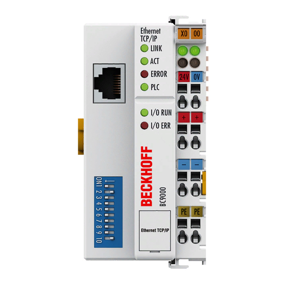
Fig. 49 BC9000 - Leds
Fig. 50 BC9100 - Leds
General Errors
ADS Diagnostics
Fig. 51 Status Inputs of the BC9000
Fig. 52 Task Time Longer than Ethernet Propagation Delay
Fig. 53 Task Time Shorter than Ethernet Propagation Delay
Modbustcp Diagnostic
9 Appendix
General Operating Conditions
Approvals
Fig. 54 Sticker with Information about the BK2000 Bus Coupler Certification
Test Standards for Device Testing
Bibliography
List of Abbreviations
Support and Service
List of Illustrations
Advertisement
Quick Links
1
Principle of the Bus Terminal
2
Configuration Using the System Manager
3
Twincat Plc
Download this manual
Documentation
BC9000 and BC9100
Bus Terminal Controller for Ethernet
Version:
Date:
4.0.0
2019-05-29
Table of
Contents
Previous
Page
Next
Page
1
2
3
4
5
Advertisement
Chapters
Table of Contents
3
List of Illustrations
89
Table of Contents
Need help?
Do you have a question about the BC9000 and is the answer not in the manual?
Ask a question
Questions and answers
Related Manuals for Beckhoff BC9000
Controller Beckhoff BK7300 User Manual
(8 pages)
Controller Beckhoff BC9100 Documentation
Bus terminal controller for ethernet (90 pages)
Controller Beckhoff BX Series Documentation
Bus terminal controller (149 pages)
Controller Beckhoff BX8000 Documentation
Bus terminal controller (149 pages)
Controller Beckhoff BC**50 Series Documentation
Bus terminal controller for devicenet (90 pages)
Controller Beckhoff BC5250 Documentation
Bus terminal controller for devicenet (90 pages)
Controller Beckhoff BC8050 Documentation
Bus terminal controller with rs485 or rs232 interface (93 pages)
Controller Beckhoff BC8150 Documentation
Bus terminal controller with rs485 or rs232 interface (93 pages)
Controller Beckhoff BC2000 Technical Documentation Manual
Bus terminal controller (28 pages)
Controller Beckhoff BC7300 Manual
Modbus bus terminal controller (48 pages)
Controller Beckhoff BC3150 Documentation
Bus terminal controller for profibus-dp (104 pages)
Controller Beckhoff CX8080 Documentation
The cx8080 is a controller with an ethernet port and two serial interfaces (67 pages)
Controller Beckhoff C6930 Installation And Operating Instructions Manual
Control cabinet pc (31 pages)
Controller Beckhoff C9900-G00 Series Manual
Push button extension (45 pages)
Controller Beckhoff CX90 0 Series Hardware Documentation
Ethernet controller (61 pages)
Controller Beckhoff EK1960 Series Operating Instructions Manual
Twinsafe compact controller (145 pages)
This manual is also suitable for:
Bc9100
Table of Contents
Save PDF
Print
Rename the bookmark
Delete bookmark?
Delete from my manuals?
Login
Sign In
OR
Sign in with Facebook
Sign in with Google
Upload manual
Upload from disk
Upload from URL


Need help?
Do you have a question about the BC9000 and is the answer not in the manual?
Questions and answers