
Related Manuals for Beckhoff BC2000


Summary of Contents for Beckhoff BC2000
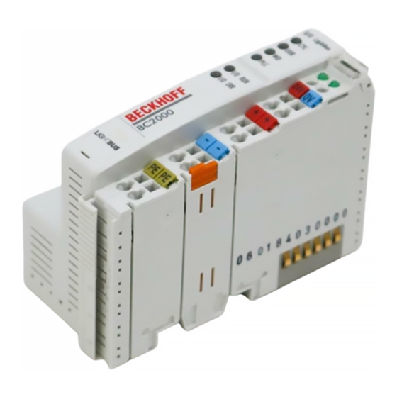
- Page 1 LIGHTBUS Bus Terminal Controller BC2000 Technical Documentation Version 1.1 2006-11-06...
- Page 2 © This manual is copyrighted. Any reproduction or third party use of this protected publication, whether in whole or in part, without the written permission of Elektro Beckhoff GmbH, is forbidden.
-
Page 3: Table Of Contents
Galvanic isolation Operating Modes of the Bus Terminal Controller Mechanical structure Preparing for Operation and Diagnostics 3. The Beckhoff BC2000 Lightbus Coupler Introduction to the Beckhoff Lightbus System 4. Settings in the TwinCAT System Manager Basic Settings PLC Cycle Time... -
Page 4: Foreword
In addition, the general delivery conditions of the company Beckhoff Automation GmbH apply. Copyright © This documentation is copyrighted. Any reproduction or third party use of this publication, whether in whole or in part, without the written permission of Beckhoff Automation GmbH, is forbidden. BC2000... -
Page 5: Safety Instructions
All the components are supplied in particular hardware and software configurations appropriate for the application. Modifications to hardware or software configurations other than those described in the documentation are not permitted, and nullify the liability of Beckhoff Automation GmbH. Description of safety symbols The following safety symbols are used in this documentation. -
Page 6: Basic Principles
Basic Principles Basic Principles Description of the BC2000 The BC2000 is a slave with PLC functionality. It has a fieldbus interface, the Lightbus. The bus terminal controller is programmable, and is programmed using the TwinCAT software in the IEC61131-3 programming languages. - Page 7 The bus terminal controller (BC) differs from the bus coupler (BK) in that in the bus terminal controllers addition to operating the terminal bus, a PLC task runs in the BC2000. Unlike bus couplers, the signals from the terminals are processed by the PLC task, while the fieldbus carries the in- and outputs of the PLC task.
-
Page 8: The Interfaces
Fieldbus, terminal bus and I/O level are galvanically isolated. The interfaces A bus terminal controller has six different methods of connection. These interfaces are designed as plug connectors and as spring-loaded terminals. The Beckhoff BC2000 Lightbus coupler II/O-Lightbus Power LEDs... -
Page 9: Power Contacts
Fieldbus connection There is a recessed front face on the left hand side. The typical Beckhoff Beckhoff Lightbus Lightbus connector can be inserted here. The Beckhoff Lightbus consists Fibre optic ring of an optical fibre ring into which the bus terminal controller is inserted. -
Page 10: Operating Modes Of The Bus Terminal Controller
„STOP“ state. Once the start-up has completed without error, the bus terminal controller enters the "fieldbus start" state. Start-up behaviour of the bus terminal controller Power On self test Bus terminal test Structure list Error PLC Start / Stop Communication start BC2000... -
Page 11: Mechanical Structure
Mechanical structure The system of the Beckhoff bus terminals is characterised by low physical volume and high modularity. When planning a project it must be assumed that at least one bus terminal controller and a number of bus terminals will be used. - Page 12 Relative humidity 95% without dew formation Vibration/shock stability according to IEC 68-2-6 / IEC 68-2-27 EMC immunity, burst / ESD according to EN 61000-4-4 / EN 61000-4-2, limit values in accordance with EN 50082-2 Installation location arbitrary Protection class IP20 BC2000...
-
Page 13: Preparing For Operation And Diagnostics
The red LED blinks with two different frequencies. The error is encoded in the blinks as follows: Blink code Fast blinking Start of the error code First slow sequence Error type Second slow sequence Error location Start of the error code Error type Error location BC2000... - Page 14 Fieldbus errors The fieldbus status LEDs indicate the operational state of the fieldbus. The functions of the Beckhoff Lightbus are indicated by the „CYC“, „ERR“ and „WD“ LEDs. The meaning of the first three LEDs is: the LED lights up for the duration of each telegram...
- Page 15 Basic Principles PLC LED If the PLC LED lights, the program has started on the BC2000. The LED flashes while a boot project is being created. Diagnostic LEDs on the BC2000 The bus terminal controller interrogates the configuration of the bus terminals after it has been switched on, then performs exchange of data with the terminals.
-
Page 16: The Beckhoff Bc2000 Lightbus Coupler
A single master system can be implemented with the Beckhoff Lightbus. A device types maximum of 254 slaves can be connected to one bus. In the BC2000 bus terminal controller, a station address between 1 and 254 is automatically selected during the start-up phase. The specifications for the system... - Page 17 The Beckhoff BC2000 Lightbus Coupler Master interfaces supporting the bus terminal controller are the PC cards C1220 as from Version 4.01, and the FC200x. These cards are supported by TwinCAT software as from version 2.6 (build 315). Fundamental properties of...
-
Page 18: Settings In The Twincat System Manager
The terminals that are assigned to the master are invisible to the bus terminal controller. If it is desired to make a terminal visible to both systems, the terminal must first be assigned to the BC2000, and then the data from the terminal are transmitted to the master via the PLC variables. -
Page 19: Plc Cycle Time
Before initiating the program, the bus terminal controller executes a terminal bus update, in order to interrogate the inputs. After the program has been executed, the BC2000 carries out another terminal bus update, in order to write the current outputs. The background time follows this. -
Page 20: Remanent Variables
(Only for TwinCAT) TwinCAT offers two target platforms, the PC as a controller and the BC2000 coupler. For the program transfer with the bus terminal controller there are again two possibilities. -
Page 21: Program Download Via The Rs232 Interface
PLC Control for this. The function blocks are contained in the „PLCSystem.lib“ library. It is also equally possible to call the ADS functions from AdsOCX. The properties of the PLC runtime system can be retrieved through port number 800, while port number 100 give access to the BC2000... -
Page 22: Plc Runtime System
Settings in the TwinCAT System Manager registers of the bus terminal controller and the terminals. PLC Runtime System Port 800 The port number in the BC2000 for the PLC is fixed at 800. Index Group / Index Offset Index Group Meaning... -
Page 23: Registers Of The Bus Terminal Controller
Settings in the TwinCAT System Manager Registers of the Bus Terminal Controller Port 100 The port number in the BC2000 for register communication is fixed at 100. Index Offset Meaning Index Group / Index Offset Index Group High WORD Low WORD... -
Page 24: Settings In Twincat Plc
Settings in TwinCAT PLC Settings in TwinCAT PLC Some of the settings for the BC2000 are only possible in PLC Control. These are primarily a matter of properties that have a direct effect on the program. The points that follow here are found in PLC Control under „ONLINE“... -
Page 25: Coupler Options
The maximum memory size is 64 kbyte. In the „large memory model“ a maximum of 96 kbyte program memory and 64 kbyte data memory are the upper limits. It should be noted that in the „large memory model“ the EEPROM is also used. BC2000... -
Page 26: Appendix
INT Offset0_2 INT Offset0_2 Inputs Outputs Terminals 2, 3, 6, 7 and 10 are directly assigned to the Lightbus master, and are therefore neither visible to the BC2000, nor do they appear in the PLC’s input and output process image. BC2000... -
Page 27: Index
Index ADS Functions 18 K bus 4 Assembly 8 Lightbus 13 Background time 16 Lightbus connector 6 BC2000 dimensions 8 Blink code 10 Boot project 21 Manufacturer’s configuration 21 Master interface 13 Mechanical structure 8 Configuration Interface 6 Connection 8... -
Page 28: Support And Service
Please contact your Beckhoff branch office or representative for local support and service on Beckhoff products! The addresses of Beckhoff's branch offices and representatives round the world can be found on her internet pages: http://www.beckhoff.com You will also find further documentation for Beckhoff components there.
Need help?
Do you have a question about the BC2000 and is the answer not in the manual?
Questions and answers