
Related Manuals for Beckhoff BC3150


Summary of Contents for Beckhoff BC3150
- Page 1 Documentation BC3150 Bus Terminal Controller for PROFIBUS-DP Version: 2.1.0 Date: 2017-07-11...
-
Page 3: Table Of Contents
Technical data .......................... 10 2.3.1 Technical Data - BCxx50 .................... 10 2.3.2 Technical data - PROFIBUS-DP .................. 12 2.3.3 Technical Data - PLC ....................... 12 The Beckhoff Bus Terminal system .................... 13 3 Mounting and wiring .......................... 15 Mounting ............................ 15 3.1.1 Dimensions ........................ 15 3.1.2 Installation ........................ 16 Wiring............................ - Page 4 7 Error handling and diagnosis......................... 88 Diagnostics ........................... 88 Diagnostic LEDs ........................... 89 8 Appendix .............................. 92 First steps with the BC3150...................... 92 Switching between controllers ...................... 94 Firmware Update .......................... 96 General operating conditions...................... 98 Test standards for device testing.................... 100 Bibliography ..........................
-
Page 5: Foreword
The TwinCAT Technology is covered, including but not limited to the following patent applications and patents: EP0851348, US6167425 with corresponding applications or registrations in various other countries. ® EtherCAT is registered trademark and patented technology, licensed by Beckhoff Automation GmbH, Germany Copyright © Beckhoff Automation GmbH & Co. KG, Germany. -
Page 6: Safety Instructions
All the components are supplied in particular hardware and software configurations appropriate for the application. Modifications to hardware or software configurations other than those described in the documentation are not permitted, and nullify the liability of Beckhoff Automation GmbH & Co. KG. Personnel qualification This description is only intended for trained specialists in control, automation and drive engineering who are familiar with the applicable national standards. -
Page 7: Documentation Issue Status
• Minor routine corrections (typing errors, spelling, etc.) • English version available 1.0.0 • First public issue (only in German) Firmware BC3150 For updating your firmware you need a serial cable [} 53], the KS2000 configuration software, or the firmware update program. Firmware... -
Page 8: Product Overview
The BCxx50 devices are programmed according to the powerful IEC 61131-3 standard. Like for all other BECKHOFF controllers, the TwinCAT automation software is the basis for parameterization and programming. Users therefore have the familiar TwinCAT tools available, e.g. PLC programming interface, System Manager and TwinCAT Scope. -
Page 9: The Principle Of The Bus Terminal
Product overview The principle of the Bus Terminal Fig. 1: The principle of the Bus Terminal BC3150 Version: 2.1.0... -
Page 10: Technical Data
Product overview Technical data 2.3.1 Technical Data - BCxx50 Technical data BC3150 Processor 16 bit micro-controller Diagnostic LEDs 2 x power supply, 2 x K-Bus Configuration and programming TwinCAT PLC software Fieldbus interface BC3150 Fieldbus PROFIBUS-DP Interfaces Serial interface COM1 (RS232 for configuration and programming, automatic baud rate... - Page 11 Product overview Technical data BC3150 Digital peripheral signals 2040 inputs/outputs Analog peripheral signals 1024 inputs/outputs Configuration possibility via TwinCAT or the controller Maximum fieldbus byte number depending on fieldbus Maximum number of bytes - PLC 2048 bytes of input data, 2048 bytes of output data...
-
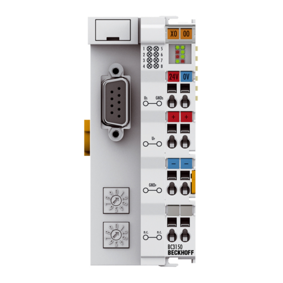
Page 12: Technical Data - Profibus-Dp
Technical data - PROFIBUS-DP Fig. 2: BC3150 System data PROFIBUS (BC3150) Number of I/O modules 126 (BC3150 max. 99 devices) Number of I/O points depending on controller Data transfer medium shielded copper cable 2 x 0.25 mm², cable type A according to EN 50 170... -
Page 13: The Beckhoff Bus Terminal System
Bus Couplers for all usual bus systems The Beckhoff Bus Terminal system unites the advantages of a bus system with the possibilities of the compact series terminal. Bus Terminals can be driven within all the usual bus systems, thus reducing the controller parts count. - Page 14 When converting to a different bus system it is necessary to bear in mind the need to change the timeout periods if the bus cycle time is longer. The interfaces A Bus Coupler has six different methods of connection. These interfaces are designed as plug connectors and as spring-loaded terminals. Version: 2.1.0 BC3150...
-
Page 15: Mounting And Wiring
3.1.1 Dimensions The Beckhoff Bus Terminal system is characterized by low physical volume and high modularity. When planning a project it must be assumed that at least one Bus Coupler and a number of Bus Terminals will be used. The mechanical dimensions of the Bus Couplers are independent of the fieldbus system. -
Page 16: Installation
The spring-loaded terminal is opened with a screwdriver or rod, by exerting gentle pressure in the opening above the terminal. The wire can be inserted into the terminal without any force. The terminal closes automatically when the pressure is released, holding the wire safely and permanently. Version: 2.1.0 BC3150... -
Page 17: Wiring
3.2.1 Potential groups, insulation testing and PE Potential groups A Beckhoff Bus Terminal block usually has three different potential groups: • The fieldbus interface is electrically isolated (except for individual Low Cost couplers) and forms the first potential group. • Bus Coupler / Bus Terminal Controller logic, K-bus and terminal logic form a second electrically isolated potential group. -
Page 18: Fig. 7 Power Contact On The Left
10 mm out from the connected group of other terminals. In that case, the PE conductors do not have to be disconnected. The power contact with the label PE must not be used for other potentials. Version: 2.1.0 BC3150... -
Page 19: Power Supply
• from an isolated source protected by a fuse of max. 4 A (according to UL248) or DANGER • from a voltage supply complying with NEC class 2. An NEC class 2 voltage source must not be connected in series or parallel with another NEC class 2 corresponding voltage source! BC3150 Version: 2.1.0... - Page 20 Bus Terminal the blade contacts on the left hand side of the Bus Terminal are connected to the spring contacts. The tongue and groove guides on the top and bottom of the Bus Terminal Controllers and of the Bus Terminals guarantees that the power contacts mate securely. Version: 2.1.0 BC3150...
-
Page 21: Profibus Connection
Fig. 12: Pin assignment of the PROFIBUS D-sub socket PROFIBUS wire colors PROFIBUS line D-Sub B red Pin 4 Pin 3 A green Pin 2 Pin 8 Connection of the Fieldbus Box modules The Fieldbus Box modules are connected either directly or via a T-piece (or Y-piece). BC3150 Version: 2.1.0... -
Page 22: Profibus Cabling
Depending on the intended application area (EMC aspects should be considered) the screening may be omitted. Two types of conductor are available, with differing maximum conductor lengths (see the RS-485 table). Version: 2.1.0 BC3150... -
Page 23: Fig. 14 Profibus Cable Assignment
Wiring errors are avoided, and commissioning is more rapidly completed. Note The Beckhoff range includes fieldbus cables, power supply cables, sensor cables and ac- cessories such as termination resistors and T-pieces. Connectors and cables for field as- sembly are nevertheless also available. - Page 24 5. Resistance between screen at the start and screen at the end of the lead: approx. 0 Ohm If these measurements are successful, the cable is okay. If, in spite of this, bus malfunctions still occur, this is usually a result of EMC interference. Observe the installation notes from the PROFIBUS User Organization (www.profibus.com). Version: 2.1.0 BC3150...
-
Page 25: Atex - Special Conditions (Extended Temperature Range)
• EN 60079-0:2012+A11:2013 • EN 60079-15:2010 Marking The Beckhoff fieldbus components with extended temperature range (ET) certified for potentially explosive areas bear the following marking: II 3G KEMA 10ATEX0075 X Ex nA IIC T4 Gc Ta: -25 … 60°C II 3G KEMA 10ATEX0075 X Ex nC IIC T4 Gc Ta: -25 … 60°C BC3150 Version: 2.1.0... -
Page 26: Parameterization And Commissioning
The I/O LEDs flash when the Bus Terminal Controller starts up. If the system is in an error-free state, the I/O LEDs should stop flashing after approx. 2-3 seconds. In the event of a fault the error type determines which LED flashes (see chapter Diagnostic LEDs). Fig. 15: Start-up behavior of the Bus Terminal Controller Version: 2.1.0 BC3150... -
Page 27: Configuration
The following is required for the TwinCAT configuration (TC file): • Via the fieldbus (PROFIBUS, CANopen, Ethernet) PROFIBUS: (BC3150, BX3100) ◦ PC with FC310x from version 2.0 and TwinCAT 2.9 build 1000 ◦ BX3100 with CIF60 or CP5412 ◦ TwinCAT 2.9 build 946 (NOTE: with PROFIBUS cards from Hilscher only one ADS communication is permitted, i.e. - Page 28 Parameterization and Commissioning ◦ BC3150, BC5150, BC5250, BC9050, BC9020, BC9120 from firmware B0 ◦ For BC8150 from TwinCAT 2.10 build 1243 BCxx50 and BXxx00 can be parameterized via the System Manager of the TwinCAT program. • Variable I/O mapping • Type-specific PROFIBUS data (BC3150 and BX3100 only) •...
-
Page 29: Creating A Twincat Configuration
All Bus Terminal Controller components are now available: • Fieldbus interface • K-bus interface [} 46] • PLC Program [} 48] • SSB (only Bus Terminal Controllers of the BX series) Please refer to the relevant chapter for device configuration. BC3150 Version: 2.1.0... -
Page 30: Downloading A Twincat Configuration
Enter the serial ADS connection, as described in the chapter Serial ADS [} 35]. ADS protocol via the fieldbus (BC3150, BC5150, BC9x20, BC9050, BX3100, BX5100, BX9000 only) A prerequisite is that TwinCAT operates as master and is engaged in data exchange, i.e. the physical and fieldbus configuration must be complete, and data exchange must take place between the master (e.g. fieldbus master card) and the Bus Terminal Controller. -
Page 31: Uploading A Twincat Configuration
Enter the serial ADS connection, as described in the chapter Serial ADS [} 35]. ADS protocol via the fieldbus (BC3150, BC5150, BC9x20, BC9050, BX3100, BX5100, BX9000 only) A prerequisite is that TwinCAT operates as master and is engaged in data exchange, i.e. the physical and fieldbus configuration must be complete, and data exchange must take place between the master (e.g. fieldbus card) and the Bus Terminal Controller. -
Page 32: Fig. 22 Choose Target System
Fig. 23: Selecting the Bus Terminal Controller The state of the Bus Terminal Controller is shown at the bottom right of the System Manager. Fig. 24: State of the Bus Terminal Controller Click on the red folder. The TwinCAT configuration will now be uploaded. Version: 2.1.0 BC3150... -
Page 33: Resources In The Bus Terminal Controller
The percentages are added here. In the example from Fig. Memory for code mapping, 8% of the memory is allocated to the mapping calculation. Fig. 26: Memory for code mapping Data memory mapping Data memory for mapping. The values are to be considered individually, i.e. each value can be up to 100%. BC3150 Version: 2.1.0... -
Page 34: Fig. 27 Data Memory Mapping
Fig. Other Memory (2) "Used Huge Heap" is required for the ADS communication. % values. This value should be less than 30 %. Fig. Other Memory (3) "Used File Area" is required for the TwinCAT configuration, the TSM file and the 16 kbyte flash access. % values. Version: 2.1.0 BC3150... -
Page 35: Ads Connection Via Serial Interface
BC9120: DEFAULT 172.16.23.[DIP-Switch].1.1 Initializing the ADS connection Enter the Bus Terminal Controller in the remote connection under TwinCAT. Click on the TwinCAT icon and open the features menu. The following settings can be made under the >AMS Remote< tab. BC3150 Version: 2.1.0... -
Page 36: Fig. 30 Properties Of The Remote Connection
Manager. In this case a new serial ADS connection is only possible, if the AMS Net ID is adjusted. BX series: reading the AMS Net ID The current AMS Net ID can be read from the menu via the display of BX series Bus Terminal Controller. AMS Net ID 1.1.1.1.1.1 Version: 2.1.0 BC3150... -
Page 37: Profibus
The PROFIBUS data can be transferred in Intel or Motorola format. Checking the DP configuration data The configuration data can • not be checked at all; • checked for correct length; or • checked for length and content BC3150 Version: 2.1.0... - Page 38 244 bytes in each direction. Download GSD file (German) (https://infosys.beckhoff.com/content/1033/bc3150/Resources/ zip/3238674315.zip) Download GSD file (English) (https://infosys.beckhoff.com/content/1033/bc3150/Resources/ zip/3238672139.zip) These files are also available from the Beckhoff website: http://www.beckhoff.de/german/download/ bkconfg.htm The GSD file can describe the following data types: Variable Length Integer 8 1 bytes...
-
Page 39: Fig. 32 Inserting Bx3100
◦ Integer 16 bit ◦ Integer 32 bit ◦ Unsigned 8 bit ◦ Unsigned 16 bit ◦ Unsigned 32 bit ◦ FLOAT 32 bit They have to match the variable types currently projected in the BX. Data sizes from 1 byte to 64 words are available. BC3150 Version: 2.1.0... -
Page 40: Fig. 33 Creating Profibus Data
ADS Communication has to be selected for preparing the configuration. If the configuration data are to be transferred via the fieldbus, data communication has to be active, i.e. the BX must be in active data exchange with the higher-level controller. Fig. 34: ADS Interface Version: 2.1.0 BC3150... -
Page 41: Fig. 35 Creating Profibus Data
Configuration. The PLC variables can now be linked with the fieldbus variables. Permitted number of PROFIBUS data Ensure that the maximum number of PROFIBUS data is not exceeded. BX3100: max. 244 byte inputs and 244 byte outputs Note BC3150: max. 128 byte inputs and 128 byte outputs BC3150 Version: 2.1.0... -
Page 42: Fig. 36 Bc3150D
• Go to Extras\Install new GSD in the hardware catalog for your Step7. • Select the directory in which the BECKHOFF GSD is located, and import the files. • You will then find them in the hardware catalog under Profibus DP\Other field devices\I/O. -
Page 43: Fig. 39 Settings
Parameterization and Commissioning 4.2.7.2.4.2 Configuration: Siemens S7 controller with BX3100 BX3100 parameter data Fig. 39: Settings BX3100 module configuration Sample 1 1 x BX3100 BC3150 Version: 2.1.0... -
Page 44: Fig. 40 Sample For Entering Individual Bytes
Parameterization and Commissioning Fig. 40: Sample for entering individual bytes. byte for byte Each individual byte requires one byte of ConfigData. Note Version: 2.1.0 BC3150... -
Page 45: Fig. 41 Sample For Entering Associated Bytes
Parameterization and Commissioning Fig. 41: Sample for entering associated bytes. BC3150 Version: 2.1.0... -
Page 46: K-Bus
If breakpoints are set in PLC Control, the K-Bus is no longer processed, i.e. the outputs are set to a safe state (zero). K-Bus Sync Mode Writing and reading of the Bus Terminals can take place synchronously with task 1 or the fieldbus. Version: 2.1.0 BC3150... -
Page 47: Fig. 43 Bx Diag Tab
Factory Settings: the Bus Terminal Controller is set to its delivery. These settings are reactivated via Restart System or by switching the system off and on again (display shows DEFAULT-CONFIG). Reset Maximum Values: resets the maximum values BC3150 Version: 2.1.0... -
Page 48: Plc
A valid project has to be compiled and saved in PLC Control. These data are saved as a *.tpy file. For inserting a PLC project, right-click on PLC - Configuration. Select your current PLC project. Fig. 44: Selecting the PLC project Link the PLC variable with the hardware (e.g. digital Bus Terminal). Version: 2.1.0 BC3150... -
Page 49: Fig. 45 Connecting Plc Variable And Hardware
Fig. 45: Connecting PLC variable and hardware Once all links have been created, activate the configuration Actions/Activate Configuration (Ctrl+Shift+F4) and start TwinCAT Set/Reset TwinCAT to Run Mode. Ensure that you have selected the correct target system (bottom right in the System Manager window). Fig. 46: Target system display BC3150 Version: 2.1.0... -
Page 50: Fig. 47 Setting The Task Time
In order to ensure trouble-free operation, the set task time should be 20-30 % higher than the measured total cycle time. A precise cycle time breakdown can be found under K-Bus tab [} 46] description. The total cycle time is displayed with the TcBase library (see TcBase.lbx or TcBaseBCxx50.lbx). Version: 2.1.0 BC3150... -
Page 51: Setting The Slave Address
(as long as the coupler is switched off), only the end terminal may be connected (KL9010), and the coupler must then has to be connected to the supply voltage. Address 99: Manufacturer's setting Address 98: Delete boot project Address 97: Delete TwinCAT configuration BC3150 Version: 2.1.0... -
Page 52: Configuration Software Ks2000
• The BX controller must be in FreeRun mode. Activate it with the TwinCAT System Manager. You can now log in with the KS2000 configuration software via ADS (port 100) or the serial cable and use the KS2000 dialogs in the Bus Terminals. Version: 2.1.0 BC3150... -
Page 53: Programming Cable
Do not interrupt the ground connection for the supply voltage When the programming cable (between BCxx50 and PC) is connected, the ground connec- tion of the Bus Terminal controller must not be interrupted or disconnected, since this may Attention destroy the programming cable. BC3150 Version: 2.1.0... -
Page 54: Programming
Limited by memory TwinCAT PLC The Beckhoff TwinCAT Software System turns any compatible PC into a real-time controller with a multi-PLC system, NC axis control, programming environment and operating station. The TwinCAT programming environment is also used for programming the BC/BX. If you have TwinCAT PLC (Windows NT4/2000/XP) installed, you can use the fieldbus connection or the serial port for downloading and debugging software. -
Page 55: Twincat Plc - Error Codes
If libraries are integrated this value may be insufficient. In this case, the number of POUs should be increased. To this end, open in PLC Control under Projects/Options... Fig. 51: Menu path Projects / Options / Controller Settings ...the controller settings. BC3150 Version: 2.1.0... -
Page 56: Fig. 52 Controller Settings
2 x 16 kbyte of data are available by default. If large data quantities are to be used, this range should be increased. A maximum of 14 data segments are possible for the BX. Fig. 54: Menu path Projects / Options / Build Version: 2.1.0 BC3150... -
Page 57: Fig. 55 Build
Programming Fig. 55: Build BC3150 Version: 2.1.0... -
Page 58: Remanent Data
A program sample can be found below. Function block test (no program code required - in ST semicolon is sufficient) FUNCTION_BLOCK Test VAR_INPUT END_VAR VAR_OUTPUT END_VAR END_VAR VAR_IN_OUT Counter :INT; END_VAR MAIN program PROGRAM MAIN fb_Test:Test; END_VAR VAR RETAIN iCounter1:INT; END_VAR fb_Test(Counter:=iCounter1); Version: 2.1.0 BC3150... -
Page 59: Allocated Flags
The maximum size of a variable or structure (array) is 16 kbyte. For the allocated data 2048 bytes of input data and 2048 bytes of output data are available. The Bus Terminal Controller has 4 kbyte of memory allocated for the flag area. BC3150 Version: 2.1.0... - Page 60 Bus Terminals. The data for PROFIBUS communication start from address offset 1000 . The length of the PROFIBUS data depends on the number of configured data. The maximum is 244 bytes for the BX3100 and 128 bytes for the BC3150. Inputs Outputs Bus Terminal %IB0 ...
-
Page 61: Mapping The Bus Terminals
Mapping the Bus Terminals The precise assignment of the byte-oriented Bus Terminals may be found in the configuration guide for the particular bus terminal. This documentation is available on the Beckhoff Products & Solutions CD or on the Internet under http://www.beckhoff.de. Byte oriented Bus Terminals... -
Page 62: Fig. 57 Linking A Variable With An Input
Bus Terminal, as required. This is parameterized in the System Manager, and the configuration is then downloaded to the Bus Terminal Controller (see TwinCAT configuration [} 27]). It is also possible to upload an existing TwinCAT configuration. Version: 2.1.0 BC3150... -
Page 63: Creating A Boot Project
1 byte. Boolean expressions should always be masked in a byte or word. Example 1: A structure on the BX/BCxx50 and on the PC Variable BX/BCxx50 memory PC memory (TwinCAT) Byte %..B0 %..B0 INT (1) %..B2 %..B1 INT (2) %..B4 %..B3 BC3150 Version: 2.1.0... -
Page 64: Up- And Downloading Of Programs
Should the memory be insufficient, the source code may be stored without task configuration and libraries. This takes up significant less memory space! General settings The timing of the source code download to the target system can be specified via Edit/Options. Open the options menu. Version: 2.1.0 BC3150... -
Page 65: Fig. 58 Opening The Options Menu
The source code can be transferred to the target system on request. This requires the user to be logged in with his program. Under Online/Source code download the program code can now be transferred to the Bus Terminal Controller. BC3150 Version: 2.1.0... -
Page 66: Fig. 60 Downloading The Program Code
After a short delay, a window will open that indicates the download progress. Fig. 61: Download progress Uploading a program For uploading the program code again, open a new file in PLC Control. Then click on the PLC button. Version: 2.1.0 BC3150... -
Page 67: Fig. 62 Uploading A Program
• BCxx50 or BX via serial, if you are connected to the Bus Terminal Controller via the serial interface. Fig. 63: Selecting the data transfer route Then select the device and confirm with OK. Fig. 64: Selecting the device The source code will now be uploaded. BC3150 Version: 2.1.0... -
Page 68: Libraries
Libraries overview The TwinCAT Automation Software offers various libraries for the BCxx50 series Bus Terminal Controllers (Bus Coupler with PLC functionality) (see BECKHOFF Information System). Download The libraries are also included in this documentation. To extract the libraries, left-click on the link and copy the libraries to directory TwinCAT\PLC\LIB. -
Page 69: Tcbasebx
Programming Controller Version Firmware BC3150 BC5150 BC5250 BC8150 FB_BasicPID File Access Version Firmware BC3150 BC5150 BC5250 BC8150 FB_ReadFromFile FB_WriteToFile FB_ReadWriteFile Memory Functions Version Firmware BC3150 BC5150 BC5250 BC8150 MEMCMP MEMCYP MEMMOVE MEMSET NOVRAM Functions Version Firmware BX3100 BX5100 BX5200 BX8000... -
Page 70: Fig. 65 Function Block F_Startdebugtimer
Calling this function starts the timer. The return value is "0". Read Debug Timer function Fig. 66: Function block F_READDEBUGTIMER This function reads the timer value. The return value has to be multiplied with 5.12 µs. Example Timer_BX :WORD; i :INT; END_VAR Program F_STARTDEBUGTIMER(); For i:=0 to 1000 do ; END_FOR Timer_BX:=F_READDEBUGTIMER(); Version: 2.1.0 BC3150... - Page 71 The type SYSTEMINFOTYPE [} 72]is declared in the system library. For accessing the variable, the system library has to be integrated in the project. Development environment Target platform PLC libraries to be linked TwinCAT v2.9.0 BCxx50, BC9x20 Controller TcBaseBCxx50.lbx BC3150 Version: 2.1.0...
- Page 72 Index group Meaning Index offset (value range) 0xF020 Inputs 0...2047 0xF030 Outputs 0...2047 0x4020 Flags 0...4095 ADS services AdsServerAdsState Data type (read only) Meaning String Start - the local PLC is running Start - the local PLC is stopped Version: 2.1.0 BC3150...
-
Page 73: Program Transfer
Every Bus Terminal Controller can be programmed via the PC's RS232 interface. Select the serial interface in TwinCAT PLC Control. Fig. 67: Selecting the data transfer route - serial interface The settings for the serial interface, port number, baud rate etc. are found under Online/Communication parameters in PLC Control. BC3150 Version: 2.1.0... -
Page 74: Fig. 68 Parameterization Of The Serial Interface
Bus Terminal Controller, TwinCAT must be notified of it (see serial ADS [} 35]). Select the ADS connection in TwinCAT PLC Control. Fig. 69: Selecting the data transfer route - AMS PLC Control can be accessed via Online/Communication Parameters..Fig. 70: Selecting the device Version: 2.1.0 BC3150... -
Page 75: Program Transfer Via Profibus
• AMS for BCxx50 and BX (Bus Terminal Controller with online change, two tasks) • BC serial – the serial cable for communication via the RS232 interface [} 73]of the PC and the programming interface of the Bus Terminal Controller BC3150 Version: 2.1.0... -
Page 76: Profibus Process Image
PROFIBUS data with PLC data, or for linking data from the K-Bus to the PROFIBUS directly. The input data of the BC3150 are output data of the master, and output data of the BC3150 are input data of the slave. - Page 77 The PROFIBUS data may therefore be located anywhere in the permissible allocated process image. Permissible process image: INPUT %IB0 - %IB2047 OUTPUT %QB0 - %QB2047 BC3150 Version: 2.1.0...
-
Page 78: Profibus
A maximum of 126 devices (master or slaves) can be connected to one bus. A station address between 0 and 99 can be chosen for the Beckhoff PROFIBUS slaves from the IPxxxx-B310, IL230x- B310 and IL230x-C310 series. The specifications for the system configuration Version: 2.1.0... - Page 79 The Beckhoff GSD files may be obtained from the internet under http://www.beckhoff.de. Diagnostic functions The extensive diagnostic functions of PROFIBUS DP allow rapid fault localization. Diagnosis of the Beckhoff Bus Coupler is not switched on in the default setting of the type file or the GSD file. The diagnostic messages are transmitted over the bus and collated by the master.
- Page 80 Here the cause of an error is related to a single input/output bit (channel), such as a short circuit on output 2 The Beckhoff PROFIBUS slaves from the IPxxxx-B310, IL230x-B310 and IL230x-C310 series support the PROFIBUS DP diagnostic functions. Assessment of the diagnostic data by means of the controller depends on the support for the PROFIBUS master.
-
Page 81: Profibus Dp
Before the master and slave can cyclically exchange data, the parameter and configuration data is transmitted from the master to the slaves during the DP StartUp phase. After the parameter and configuration data has been sent, the master interrogates the slave's diagnostic data until the slave indicates BC3150 Version: 2.1.0... - Page 82 The master distinguishes between the CLEAR state (all outputs are set to the Fail_Safe value) and the OPERATE state (all outputs have the process value). The Master is usually switched into the CLEAR mode when, for instance, the PLC enters STOP. Version: 2.1.0 BC3150...
-
Page 83: Profibus Dpv1
When two masters are used, however, is must always be borne in mind that these share bus access (a token is exchanged), so that time relationships are less favorable than in the case of a single master system. BC3150 Version: 2.1.0... -
Page 84: Plug Connectors, Cables And Switches
Preassembled cable from Beckhoff Installation is made a great deal more straightforward if preassembled cables from Beck- hoff are used. -
Page 85: Fig. 75 Profibus Cable Assignment
The change in address is active as soon as the device is switched on. Fieldbus Box address The switch on the left represents the tens, while that on the right represents the units. BC3150 Version: 2.1.0... -
Page 86: Topology
• Stubs are to be avoided, and are not permitted above 1.5 Mbaud. • The maximum number of devices is 127 • Interrupting the supply voltages from cable ends by switching off the repeater/slave, or by pulling out the plug, is not permitted. Version: 2.1.0 BC3150... -
Page 87: Fig. 78 Rs485 Topology With 3 Segments And 2 Repeaters
PROFIBUS Fig. 78: RS485 topology with 3 segments and 2 repeaters BC3150 Version: 2.1.0... -
Page 88: Error Handling And Diagnosis
16#0006 IndexOffset BX3100: 16#000C_A0F4 BC3150: 16#000C_A080 State of the K-bus An internal bus or Bus Terminal error is indicated in the K-Bus state. A more precise fault description can be obtained via a function block (in preparation). To this end, link the K-bus state variable with your PLC program. -
Page 89: Diagnostic Leds
LEDs for K-Bus diagnostics LED (Power LEDs) Meaning LED RUN LED off: no K-Bus update, LED on, flashing: K-bus running LED ERR LED off: no error, LED flashing: see K-Bus error code BC3150 Version: 2.1.0... - Page 90 KS2000 configuration software Length of the K-bus data is no Start the Bus Coupler again. If the error occurs longer correct again, restore the manufacturers setting using the KS2000 configuration software Version: 2.1.0 BC3150...
- Page 91 Bus Coupler has found baud rate, waiting for config and parameter data no error, coupler in data exchange flashing error, see error code LED PLC - PLC diagnostics Meaning PLC LED LED on: PLC running, LED off: PLC stopped BC3150 Version: 2.1.0...
-
Page 92: Appendix
(https://infosys.beckhoff.com/content/1033/bc3150/Resources/tsm/3730735499.tsm) This link contains the System Manager file for the master configuration with the FC310x PROFIBUS card and the BC3150 slaves. Select the correct PCI address for the FC3101 Fig. 82: Selecting the PCI address for the FC3101 PROFIBUS card and set PROFIBUS address [} 51] 11 on the BC3150. -
Page 93: Fig. 83 Setting The Profibus Address
Activate the configuration and start the system. The TwinCAT icon (bottom right on the desktop) should be green. The bus LED of the BC3150 must light up green. Should this not be the case, check the BC3150 address and the physical connection to the PROFIBUS master (terminating resistors etc.). -
Page 94: Switching Between Controllers
For the standard Bus Terminal Controllers (BCxx00) it was possible to select whether a Bus Terminal is assigned to the fieldbus or the local PLC. In the default configuration of the BCxx50/BCxx20 all Bus Terminals are assigned to the local PLC. An assignment to the fieldbus is not possible in this case. Version: 2.1.0 BC3150... - Page 95 *.prx. Allocated variables For the Bus Terminal controllers of the BCxx50/BCxx20 and BXxx00 series, a limited number of allocated data are available: • inputs 2 kbyte, %IB0…2048 • outputs 2 kbyte, %QB0…2048 • flags 4 kbyte, %MB0…4095 BC3150 Version: 2.1.0...
-
Page 96: Firmware Update
Note for BX3100: Updates are not available with BX3100 firmware 0.64 (or lower). If these devices need updating, send the BX3100 to the manufacturer with a corresponding note. Beckhoff Automation GmbH & Co. KG Service Department Stahlstr. 31 33415 Verl, Germany Firmware update program 241 (https://infosys.beckhoff.com/content/1033/bc3150/Resources/... -
Page 97: Fig. 86 Selecting A Bc Series Bus Terminal Controller
Start the download via the green 'traffic light'. The download begins after about a minute, and is then also shown on the BX's display. After successful download (approx. 2 to 3 minutes) the Bus Terminal Controller reboots automatically. BC3150 Version: 2.1.0... -
Page 98: General Operating Conditions
A protective conductor connection to the profile rail is 0106, Part 1) necessary! Protection class conforms to IEC 529 IP20 (protection against contact with a standard test finger) Protection against foreign objects Less than 12 mm in diameter Protection against water no protection Version: 2.1.0 BC3150... - Page 99 (Use a 4 A fuse or a Class 2 power supply to meet UL requirements) Data transfer rate 2.5 Mbaud Manufacturer Beckhoff Automation GmbH & Co. KG CE mark Conformity mark UL mark Mark for UL approval. UL stands for the Underwriters Laboratories Inc., the leading certification organization for North America, based in the USA.
-
Page 100: Test Standards For Device Testing
Practical knowledge with comparison options Published by Franzis Verlag, 2001 244 pages ISBN 3-7723-5745-8 English books (in preparation) PROFIBUS-DP standards • IEC 61158 and IEC 61784 • DIN 19245, Part 3 • Euronorm EN 50 170 Web sites • http://www.profibus.de Version: 2.1.0 BC3150... -
Page 101: List Of Abbreviations
Terminal Bus: Internal bus for communication between Bus Coupler and Bus Terminals PROFIBUS User Organization (see www.profibus.de) Repeater Provides signal conditioning, connecting individual bus segments Programmable logic controller Sync-Mode This command makes the slave hold its outputs unchanged until it receives the Sync telegram. BC3150 Version: 2.1.0... -
Page 102: Support And Service
Beckhoff's branch offices and representatives Please contact your Beckhoff branch office or representative for local support and service on Beckhoff products! The addresses of Beckhoff's branch offices and representatives round the world can be found on her internet pages: http://www.beckhoff.com You will also find further documentation for Beckhoff components there. - Page 103 List of Illustration List of Illustration Fig. 1 The principle of the Bus Terminal ....................Fig. 2 BC3150............................Fig. 3 BCxx50 ............................Fig. 4 Release the locking mechanism by pulling the orange tab............Fig. 5 Power contact on the left ......................
- Page 104 Selecting the PCI address for the FC3101 PROFIBUS card............Fig. 83 Setting the PROFIBUS address ....................Fig. 84 Selecting the BC3150 as target system..................Fig. 85 Selecting a BX series Bus Terminal Controller................Fig. 86 Selecting a BC series Bus Terminal Controller................
Need help?
Do you have a question about the BC3150 and is the answer not in the manual?
Questions and answers